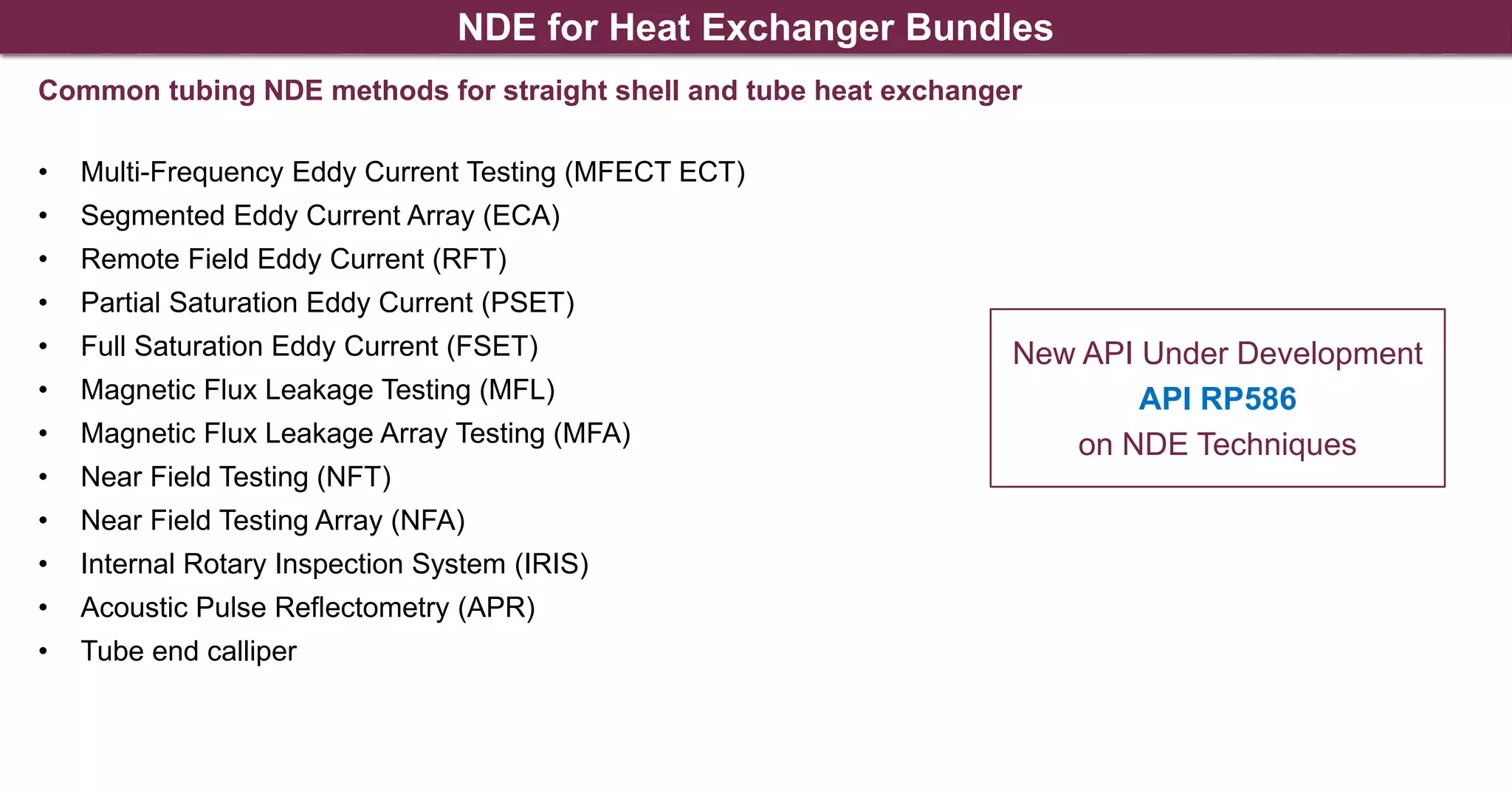
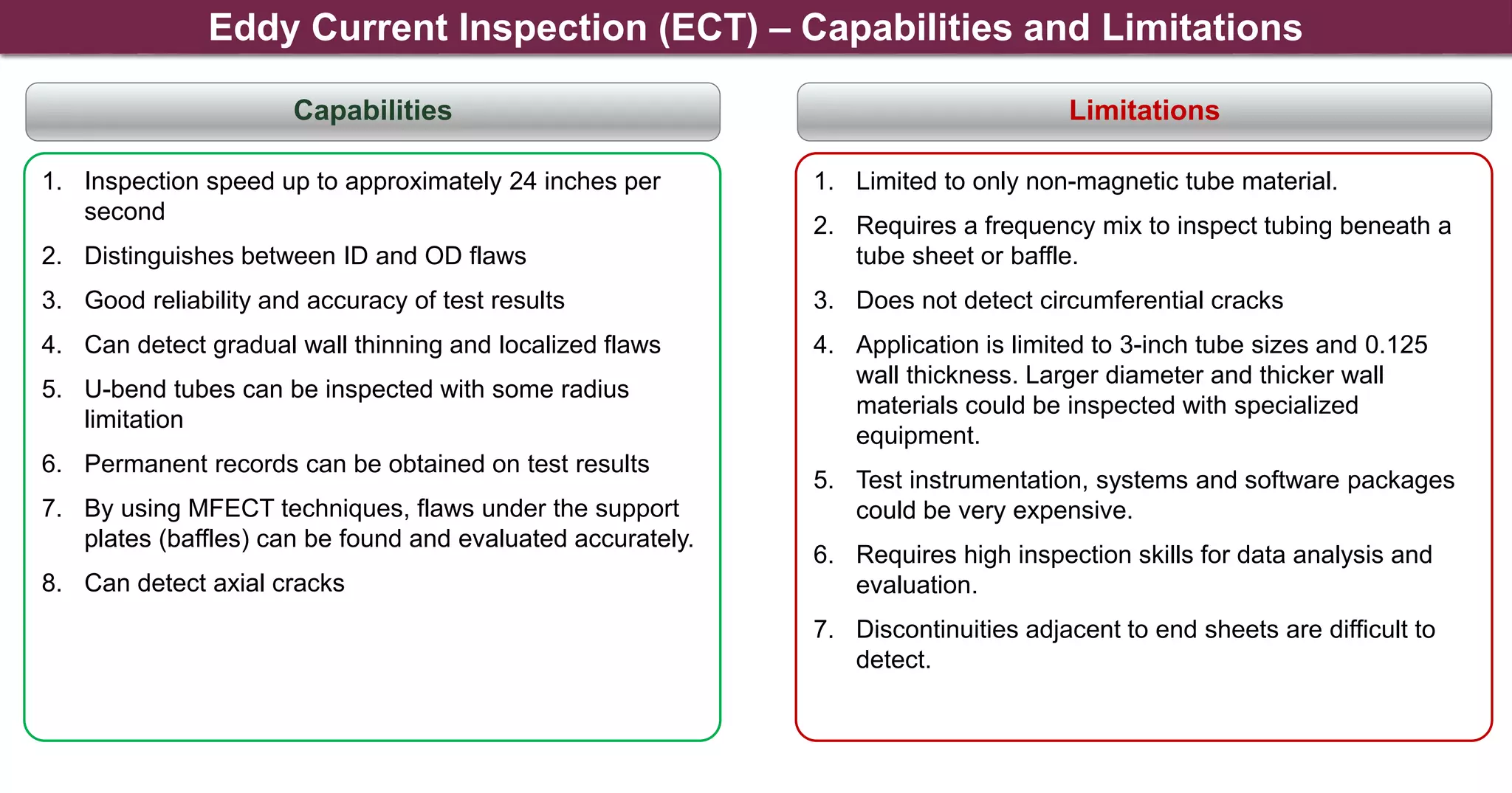
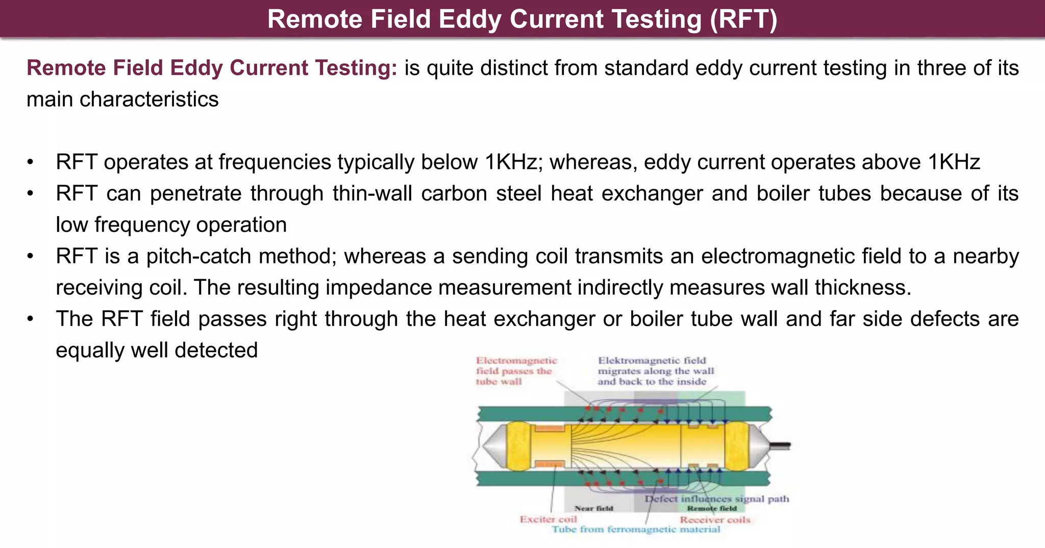
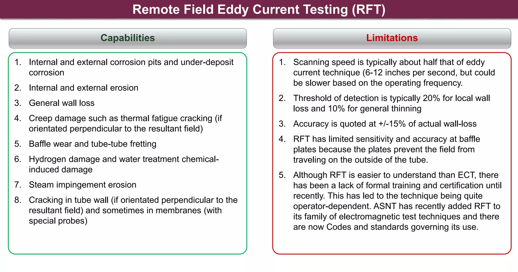
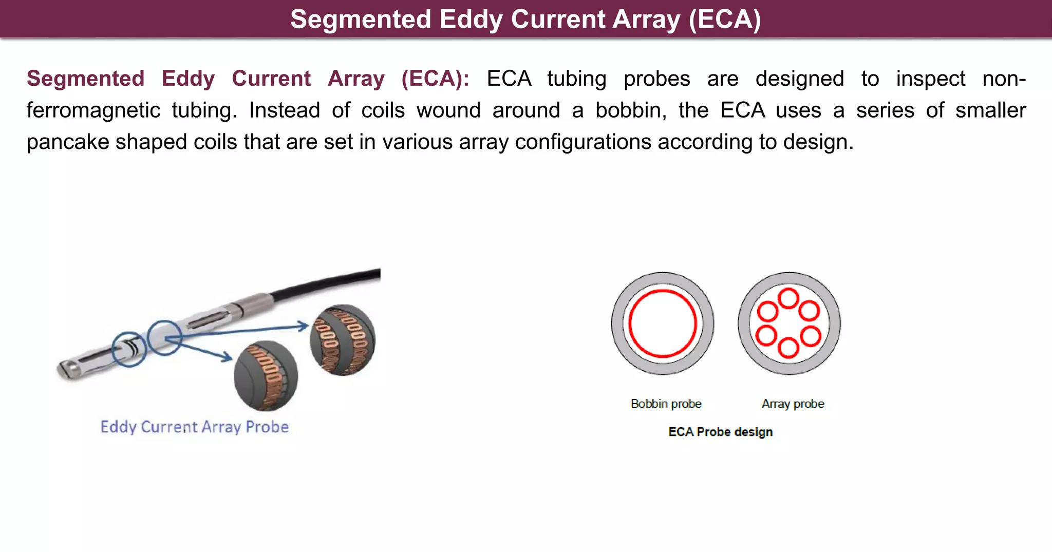
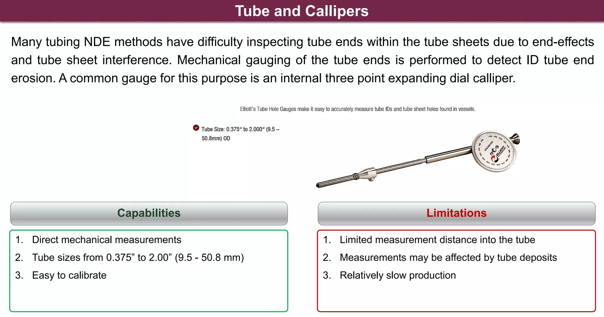
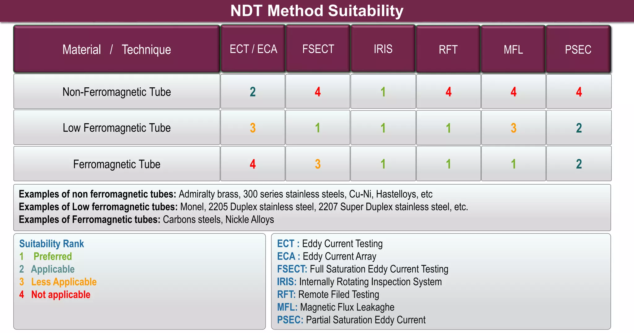
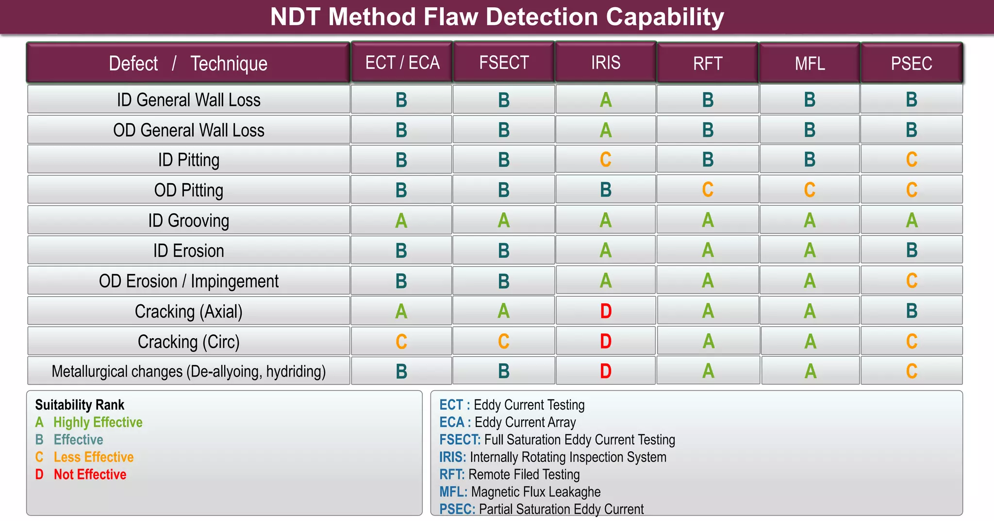
The document discusses inspection methods for shell and tube heat exchangers. It describes various non-destructive testing (NDT) methods used to inspect heat exchanger tubing, including eddy current testing, remote field eddy current testing, segmented eddy current array, internal rotary inspection system, and magnetic flux leakage testing. It also discusses limitations and capabilities of each method and considerations for inspecting U-bend tubing and tube-to-tube sheet joints.
![NDE for Heat Exchanger Bundles ASME PCC 2
Article 312
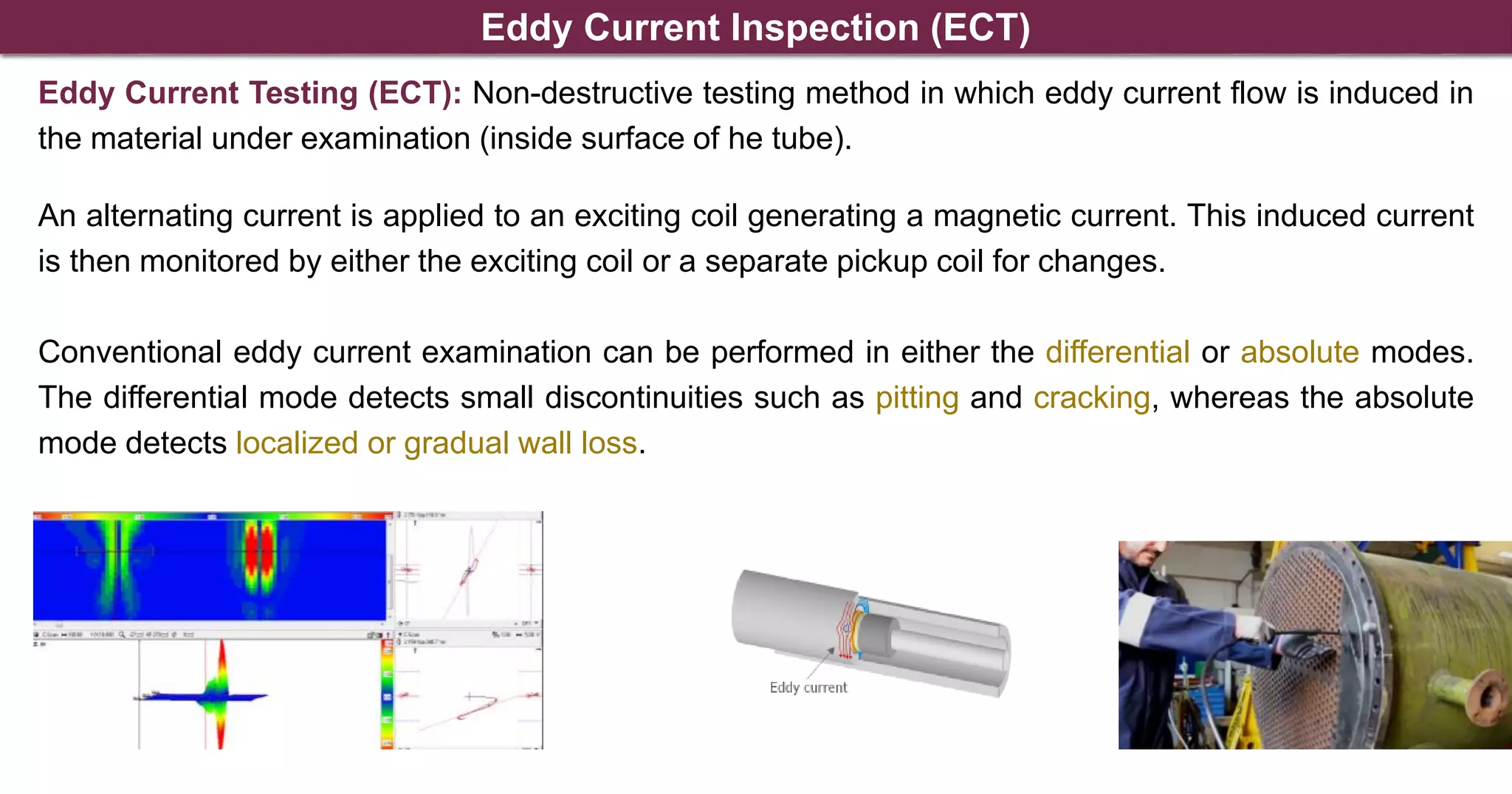
Eddy Current
Examination [ET]
Generally selected
for inspection of
nonferromagnetic
tubes, or those that
are slightly magnetic.
Note that the
sensitivity of this
method decreases
for the U-bend
portion of U-tube
bundles.
Remote Field
Eddy Current
[RFET]
Generally used for
inspection of
ferromagnetic tubes.
Its sensitivity and
accuracy may be
less than desired or
required and will
require a higher
number of tubes to
be inspected. It is a
quicker method than
ultrasonic methods
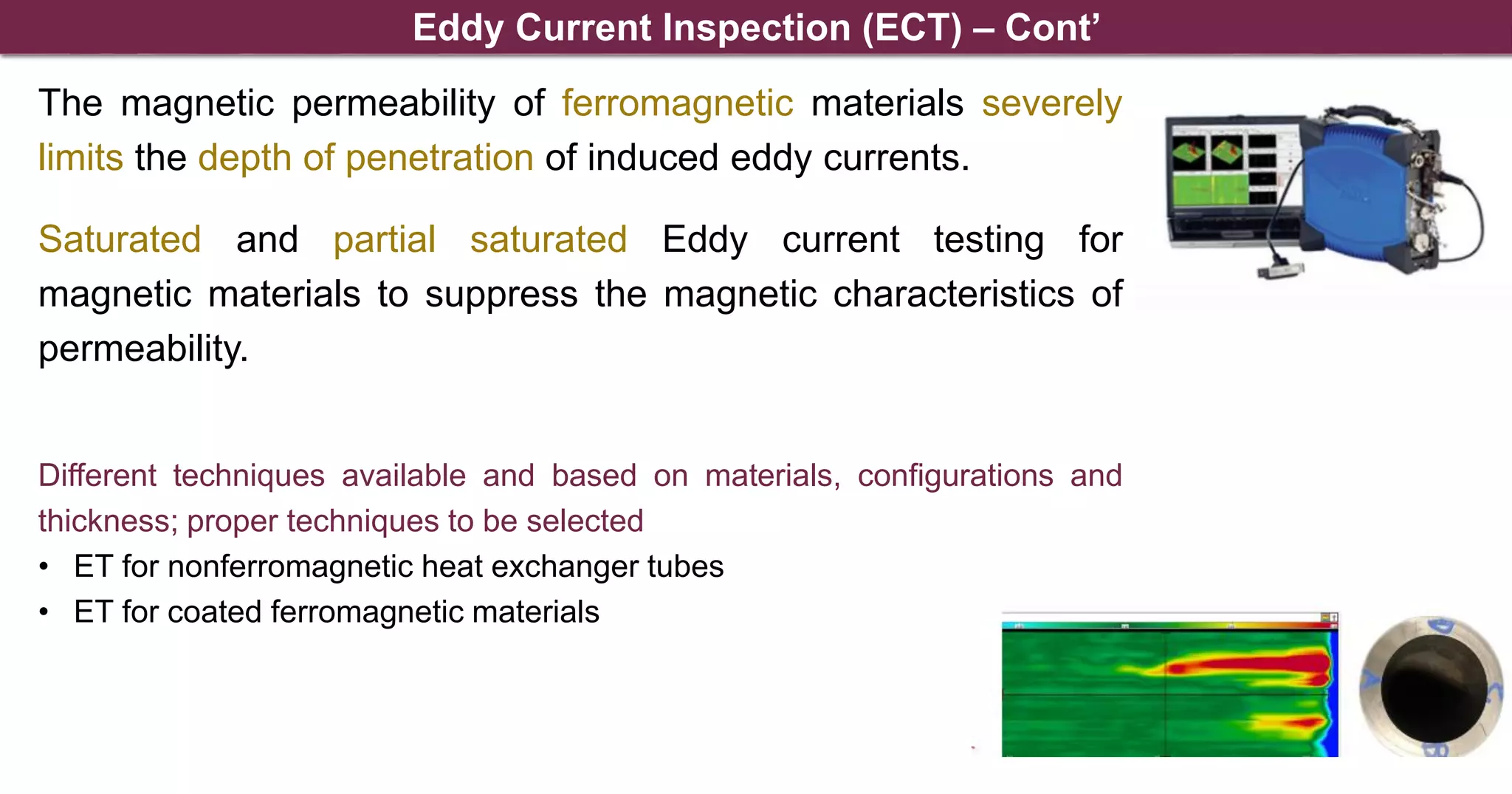
Partial Saturation
Eddy Current
[PSET]
Can locate and size
cracks in
ferromagnetic tubes.
It might not be
sensitive to O.D.
defects.
Magnetic Flux
Leakage [MFL]
May also be selected
for inspection of
ferromagnetic tubes.
However, sensitivity
of this method can be
poor for carbon steel
tubes, and might only
be best at determining
the overall condition
of the tube, not
determining individual
defect location
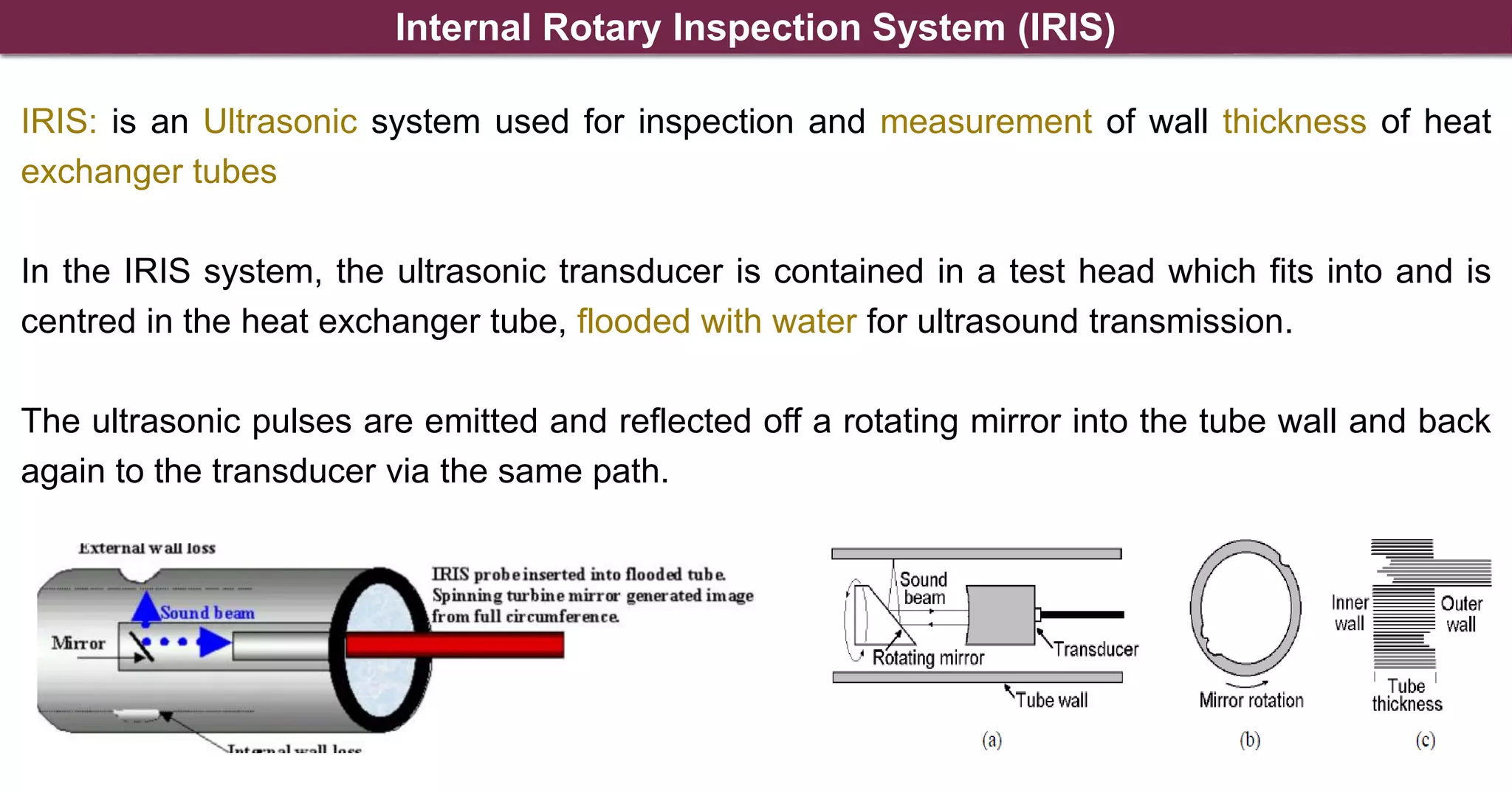
Ultrasonic systems designed
to measure tube wall
thickness
may be used for HE, where
damage may be localized, or for
validation of other NDE results.
These ultrasonic examination
systems are particularly suited
for CS tubes due to the lack of
sensitivity of other NDE methods
One type of system is the
Internal Rotary Ultrasonic
Inspection (IRIS) system. IRIS is
an accurate NDE to detect and
size I.D. and O.D. metal loss
Another type of system is Shear
Wave IRIS (SWIRIS) and this
can be effective for detecting I.D.
and O.D. cracks. Both IRIS and
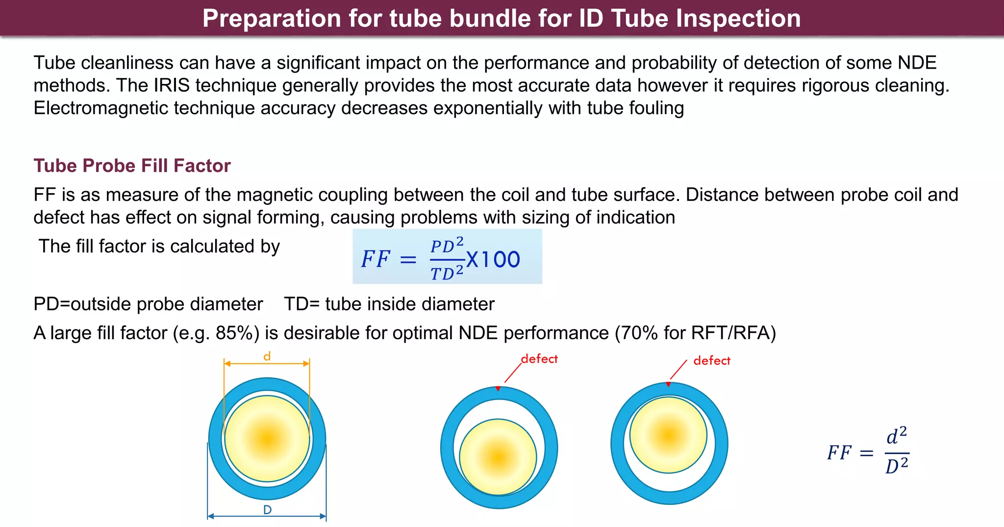
SWIRIS require clean tubes
Heat Exchangers Baher Elsheikh – Nov. 2020](https://image.slidesharecdn.com/heatexchangersinspection-220411165017/75/Heat-Exchangers-inspection-pdf-4-2048.jpg)