Downloaded 102 times

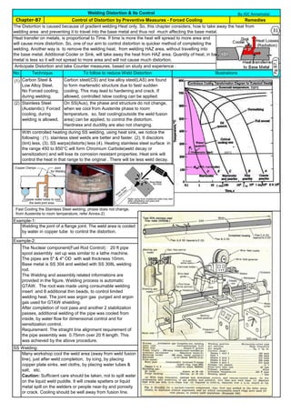
![RemediesChapter-A5 Factors Influencing Weld Distortion
By JGC Annamalai
Sr.
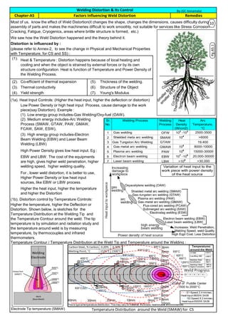
No.
Welding Process Welding
Process
Heat
Density
(W/cm2)
Arc
Temperature,
°C
1 Gas welding OFW 10
2
-10
3
2500-3500
2 Shielded meta arc welding SMAW 10
4
>6000
3 Gas Tungston Arc Welding GTAW 19,400
4 Gas metal arc welding GMAW 10
5
8000-10000
5 Plasma arc welding PAW 106
15000-30000
6 Electron beam welding EBW 107
-108
20,000-30000
7 Laser beam welding LBW >108
>30,000
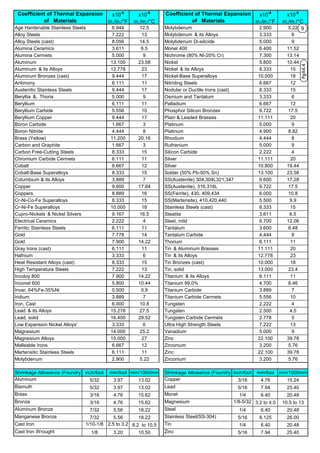
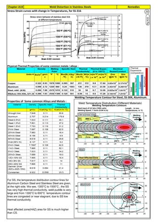
(2). Co-efficient of Thermal Expansion (higher the co-efficient of thermal expansion, higher the Deflection or Distortion)
(3). Thermal Conductivity (Higher the thermal conductivity, the heat drain is faster, distortion is less)
(4). Yield Strength (higher the yield strength, lower the Deflection or Distortion)
(5). Thickness of the Welding.
(6). The shape and complexity of the Structure
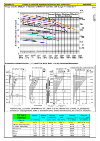
(7). E, Young's Modulus (also called Modulus of Elasticity), (Higher the E, more stiffer, lower the Deflection or Distortion)
Different materials, at the same temperature, having, higher Young's Modulus, will have higher rigidity. Material to
material, the Young's modulus will change. So, to have less distortion, have higher modulus of Elasticity or Young's
Modulus.
For most of the materials, as the temperature increases, the Young's Modulus for a particular material decreases.
So, the structure at higher temperature, will not be rigid. The structure at higher temperatures, will deform/distort
more.
The expansion and contraction is function of co-efficient of thermal expansion. Higher the thermal coefficient higher
the distortion. Stainless steel and Aluminum have high thermal coefficient. So they will expand and distort more. For
steel, thermal co-efficient is increasing as the temperature increasing.
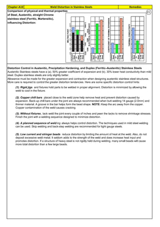
Thermal Conductivity plays a major role in Distortion. If the heat from weld pool is transferred/drained fast, the
distortion effects or less. Material with low thermal conductivity, like SS, will accumulate the heat and delay the heat
transfer and cause more distortion.
Each material has yield strength. Higher the yield strength, higher the strength and resist plastic deformation and
failure. As the temperature increases, yield stress of most of the materials decreases. Material with lower yield
strength may fail fast at lower loads. To meet the strength and to lower the weight of the structure, often Designers
prefer higher yield strength material. During welding, yield strength of the material is inversely proportional to the
welding temperature. Material with Higher yield strength at high temperature will have less weld distortion
Volume of Metal: Higher the material thickness is higher the 2nd moment of inertia and will resist distortion. Often
lower thickness material will have higher distortion. Higher thickness material will have faster spread of heat.
Volume of Weld/Thickness of Weld : Higher weld thickness or more volume of weld material, will have more
distortion.
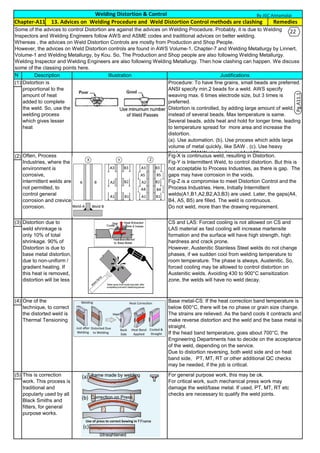
(b). On CS and LAS welding, it is problem for fast cooling, as it often leads to action similar to quenching and
formation of hard martensitic material and crack. Preheat will slow down the spread of heat. People pre-heat the
whole structure, so that faster heat draining will be prevented.
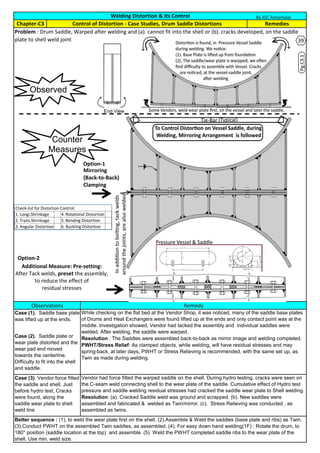
The distortion will be easily observed on simple structure, as in simple butt weld on 2 plates or on fillet weld with 2
plates . It is difficult to see the Distortion on more complex Structure. The rigidity of the structure make the distortion
absorbed /or controlled by other members or inside the structure and will stay as residual stress.
(c). Less harmful distortion, happens, on Stainless Steel, if we cool fast and drain away the welding heat. As there
is no phase change in SS, no hardening or grain change happens. On SS, area beyond weld fusion line is force
cooled, by icing or water cooling.
The following are the actions for Temperature Controls :
(a). Temperature spreads from high temperature to low temperature. If the high temperature is kept, for long time,
it will spread to more area. If the area will have high temperature for long time and more area may have yielding
further and will have more distortion. So, the welding should be completed fast. Higher the temperature, lower the
yield stress and will have more distortion.
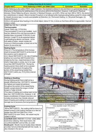
Pg.A5.2
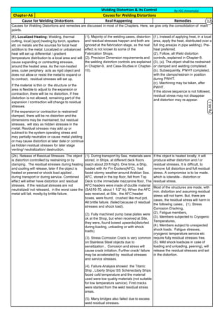
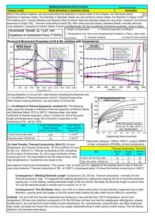
(1). Welding speed: 2.4 mm/s; heat input: 3200 W; material, similar to SA36
(2). Welding speed: 6.2 mm/s and heat input of 5000W. material, similar to Isotherm curves
are very similar, but the ellipses are compressed in Y axis and elongated in X axis
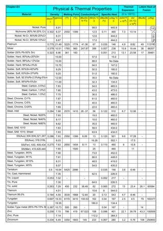
Ref: ASME Sec II, D, Page-568
Temperature, °C >>>>
−30to
40 65 100 125 150 175 200 225 250 275 300 325 350 375 400 425 450 475 500 525
Carbon steels SA36 248 233 227 223 219 216 213 209 204 199 194 188 183 177 171 166 162 158 154 150
Material Group G [SS-304, plate]207 184 170 161 154 148 144 139 135 132 129 126 123 121 118 117 114 112 110 108
Yield Strength, MPa (Multiply by 1000 to Obtain kPa), for Metal Temperature, °C, Not Exceeding
Ref: ASME Sec II, D, Page-696
Temperature, °C >>>> −200 −125 −75 25 100 150 200 250 300 350 400 450 500 550 600 650 700
Carbon steels with C ≤ 0.30% 216 212 209 202 198 195 192 189 185 179 171 162 151 137 . . . . . . . . .
Material Group G [SS-304 etc] 209 204 201 195 189 186 183 179 176 172 169 165 160 156 151 146 140
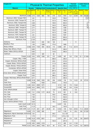
(Youngs Modulus) Modulus of Elasticity E = Value Given x 103
Mpa(or in Gpa), for Temperature, °C
Temp.°C 20°C 40°C 70°C 100°C 120°C 150°C 180°C 200°C 230°C 260°C 280°C 320°C 350°C 370°C 400°C 430°C 450°C 480°C 500°C 540°C 570°C 600°C 620°C 650°C 680°C 700°C 730°C 760°C 800°C 820°C
CS 11.52 11.70 11.88 12.06 12.24 12.42 12.60 12.78 12.96 13.14 13.14 13.32 13.50 13.68 13.86 14.04 14.22 14.22 14.40 14.58 14.58 14.76 14.94 14.94 15.12 15.12 … … … …
Aus SS 15.30 15.48 15.84 16.02 16.38 16.56 16.92 17.10 17.28 17.46 17.64 17.82 17.82 18.00 18.00 18.18 18.36 18.36 18.54 18.54 18.72 18.72 18.90 19.08 19.08 19.26 19.26 19.44 19.44 19.44
Coefficients forCarbonand LowAlloy(Coefficient is the meancoefficientofthermalexpansion×10
−6
(mm./mm./°C)ingoing from20°C,(Interpolated fromASME,SecII,D,Table-TE1)
11](https://image.slidesharecdn.com/weldingdistortionanditscontrol-200615150931/85/Welding-distortion-and-its-control-11-320.jpg)

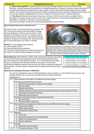
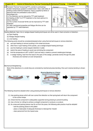
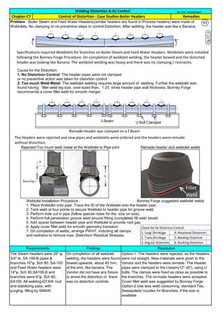
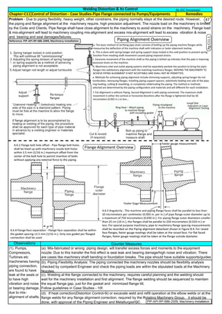

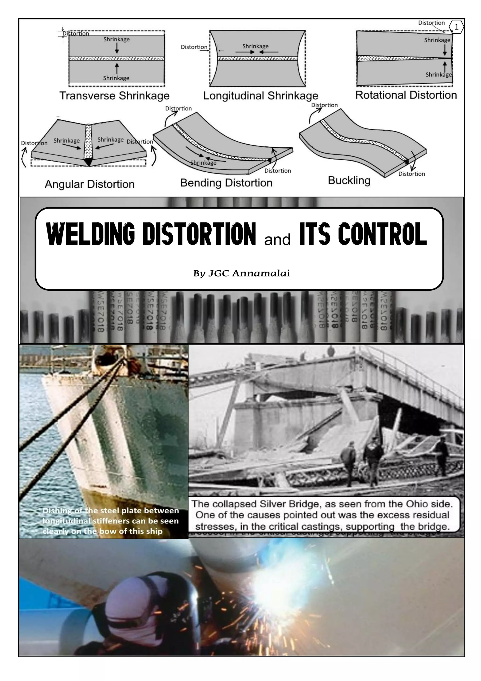
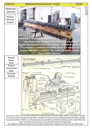
Welding causes distortion due to differential heating and cooling rates during the process. When heat is applied to part of a structure, it expands locally. If the structure is restrained from expanding uniformly, compressive and tensile stresses develop which can result in distortion. Three factors influence distortion: 1) temperature gradients between regions of the structure, 2) restraint from thermal expansion, and 3) yield strength and modulus of the material at welding temperatures. Distortion can be controlled by techniques such as pre-setting parts, clamping during welding, and post-weld heat treatment.


![Welding 2[EDocFind.com]](https://cdn.slidesharecdn.com/ss_thumbnails/cef0456c-72db-4c24-9232-061dfa358ef1-151012162903-lva1-app6892-thumbnail.jpg?width=640&height=640&fit=bounds)


