WELDING PROCESSES
1. ArcWelding
2. Resistance Welding
3. Oxyfuel Gas Welding
4. Other Fusion Welding Processes
5. Solid State Welding
6. Weld Quality
7. Weldability
8. Design Considerations in Welding
2
3.
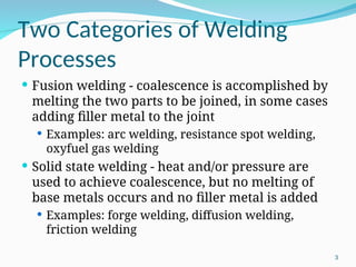
Two Categories ofWelding
Processes
Fusion welding - coalescence is accomplished by
melting the two parts to be joined, in some cases
adding filler metal to the joint
Examples: arc welding, resistance spot welding,
oxyfuel gas welding
Solid state welding - heat and/or pressure are
used to achieve coalescence, but no melting of
base metals occurs and no filler metal is added
Examples: forge welding, diffusion welding,
friction welding
3
4.
Arc Welding (AW)
Afusion welding process in which coalescence of
the metals is achieved by the heat from an
electric arc between an electrode and the work
Electric energy from the arc produces
temperatures ~ 10,000 F (5500 C), hot enough to
melt any metal
Most AW processes add filler metal to increase
volume and strength of weld joint
4
5.
What is anElectric Arc?
An electric arc is a discharge of electric current
across a gap in a circuit
It is sustained by an ionized column of gas
(plasma) through which the current flows
To initiate the arc in AW, electrode is brought
into contact with work and then quickly
separated from it by a short distance
5
6.
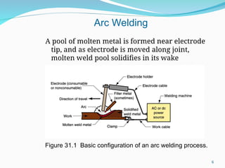
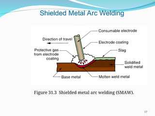
A pool ofmolten metal is formed near electrode
tip, and as electrode is moved along joint,
molten weld pool solidifies in its wake
Figure 31.1 Basic configuration of an arc welding process.
Arc Welding
6
7.
Manual Arc Weldingand Arc
Time Problems with manual welding:
Weld joint quality
Productivity
Arc Time = (time arc is on) divided by
(hours worked)
Also called “arc-on time”
Manual welding arc time = 20%
Machine welding arc time ~ 50%
7
8.
Two Basic Typesof AW
Electrodes
Consumable – consumed during welding process
Source of filler metal in arc welding
Nonconsumable – not consumed during welding
process
Filler metal must be added separately
8
9.
Consumable Electrodes
Formsof consumable electrodes
Welding rods (a.k.a. sticks) are 9 to 18 inches and
3/8 inch or less in diameter and must be changed
frequently
Weld wire can be continuously fed from spools
with long lengths of wire, avoiding frequent
interruptions
In both rod and wire forms, electrode is
consumed by arc and added to weld joint as filler
metal
9
10.
Nonconsumable Electrodes
Madeof tungsten which resists melting
Gradually depleted during welding (vaporization
is principal mechanism)
Any filler metal must be supplied by a separate
wire fed into weld pool
10
11.
Arc Shielding
Athigh temperatures in AW, metals are
chemically reactive to oxygen, nitrogen, and
hydrogen in air
Mechanical properties of joint can be seriously
degraded by these reactions
To protect operation, arc must be shielded from
surrounding air in AW processes
Arc shielding is accomplished by:
Shielding gases, e.g., argon, helium, CO2
Flux
11
12.
Flux
A substance thatprevents formation of oxides and
other contaminants in welding, or dissolves them
and facilitates removal
Provides protective atmosphere for welding
Stabilizes arc
Reduces spattering
12
13.
Various Flux Application
Methods
Pouring granular flux onto welding operation
Stick electrode coated with flux material that
melts during welding to cover operation
Tubular electrodes in which flux is contained in
the core and released as electrode is consumed
13
14.
Power Source inArc Welding
Direct current (DC) vs. Alternating current (AC)
AC machines less expensive to purchase and
operate, but generally restricted to ferrous metals
DC equipment can be used on all metals and is
generally noted for better arc control
14
15.
Consumable Electrode AW
Processes
Shielded Metal Arc Welding
Gas Metal Arc Welding
Flux‑Cored Arc Welding
Electrogas Welding
Submerged Arc Welding
15
16.
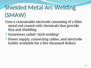
Shielded Metal ArcWelding
(SMAW)
Uses a consumable electrode consisting of a filler
metal rod coated with chemicals that provide
flux and shielding
Sometimes called "stick welding"
Power supply, connecting cables, and electrode
holder available for a few thousand dollars
16
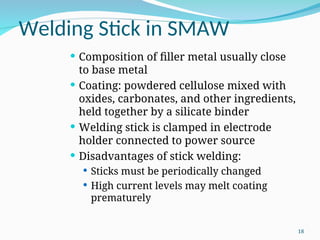
Welding Stick inSMAW
Composition of filler metal usually close
to base metal
Coating: powdered cellulose mixed with
oxides, carbonates, and other ingredients,
held together by a silicate binder
Welding stick is clamped in electrode
holder connected to power source
Disadvantages of stick welding:
Sticks must be periodically changed
High current levels may melt coating
prematurely
18
19.
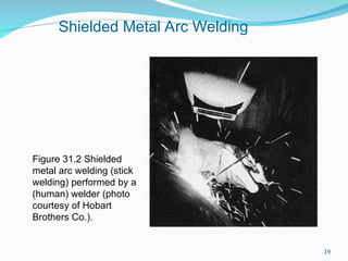
Figure 31.2 Shielded
metalarc welding (stick
welding) performed by a
(human) welder (photo
courtesy of Hobart
Brothers Co.).
Shielded Metal Arc Welding
19
20.
SMAW Applications
Usedfor steels, stainless steels,
cast irons, and certain nonferrous
alloys
Not used or rarely used for
aluminum and its alloys, copper
alloys, and titanium
20
21.
Gas Metal ArcWelding (GMAW)
Uses a consumable bare metal wire as
electrode and shielding accomplished by
flooding arc with a gas
Wire is fed continuously and automatically
from a spool through the welding gun
Shielding gases include inert gases such as
argon and helium for aluminum welding,
and active gases such as CO2 for steel
welding
Bare electrode wire plus shielding gases
eliminate slag on weld bead - no need for
manual grinding and cleaning of slag
21
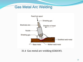
22.
31.4 Gas metalarc welding (GMAW).
Gas Metal Arc Welding
22
23.
GMAW Advantages over
SMAW
Better arc time because of continuous wire
electrode
Sticks must be periodically changed in SMAW
Better use of electrode filler metal than SMAW
End of stick cannot be used in SMAW
Higher deposition rates
Eliminates problem of slag removal
Can be readily automated
23
24.
Flux Cored ArcWelding (FCAW)
‑
Adaptation of shielded metal arc welding, to
overcome limitations of stick electrodes
Electrode is a continuous consumable tubing (in
coils) containing flux and other ingredients (e.g.,
alloying elements) in its core
Two versions:
Self‑shielded FCAW - core includes compounds
that produce shielding gases
Gas‑shielded FCAW - uses externally applied
shielding gases
24
25.
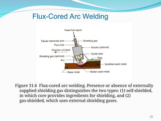
Figure 31.6 Flux‑coredarc welding. Presence or absence of externally
supplied shielding gas distinguishes the two types: (1) self‑shielded,
in which core provides ingredients for shielding, and (2)
gas‑shielded, which uses external shielding gases.
Flux-Cored Arc Welding
25
26.
Electrogas Welding (EGW)
Usesa continuous consumable electrode, either
flux‑cored wire or bare wire with externally
supplied shielding gases, and molding shoes to
contain molten metal
When flux‑cored electrode wire is used and no
external gases are supplied, then special case of
self‑shielded FCAW
When a bare electrode wire used with shielding
gases from external source, then special case of
GMAW
26
27.
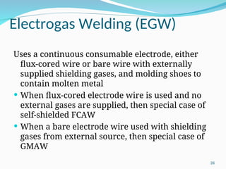
Figure 31.7 Electrogaswelding using flux‑cored electrode wire:
(a) front view with molding shoe removed for clarity, and (b)
side view showing molding shoes on both sides.
Electrogas Welding
27
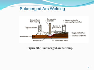
28.
Submerged Arc Welding(SAW)
Uses a continuous, consumable bare
wire electrode, with arc shielding
provided by a cover of granular flux
Electrode wire is fed automatically
from a coil
Flux introduced into joint slightly
ahead of arc by gravity from a hopper
Completely submerges operation,
preventing sparks, spatter, and
radiation
28
SAW Applications andProducts
Steel fabrication of structural shapes (e.g.,
I‑beams)
Seams for large diameter pipes, tanks, and
pressure vessels
Welded components for heavy machinery
Most steels (except hi C steel)
Not good for nonferrous metals
30
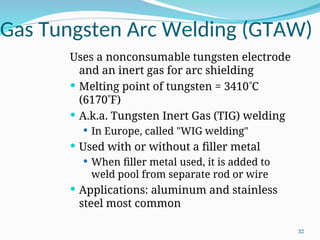
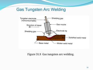
Gas Tungsten ArcWelding (GTAW)
Uses a nonconsumable tungsten electrode
and an inert gas for arc shielding
Melting point of tungsten = 3410C
(6170F)
A.k.a. Tungsten Inert Gas (TIG) welding
In Europe, called "WIG welding"
Used with or without a filler metal
When filler metal used, it is added to
weld pool from separate rod or wire
Applications: aluminum and stainless
steel most common
32
33.
Figure 31.9 Gastungsten arc welding.
Gas Tungsten Arc Welding
33
34.
Advantages / Disadvantagesof
GTAW
Advantages:
High quality welds for suitable applications
No spatter because no filler metal through arc
Little or no post-weld cleaning because no flux
Disadvantages:
Generally slower and more costly than consumable
electrode AW processes
34
35.
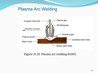
Plasma Arc Welding(PAW)
Special form of GTAW in which a constricted
plasma arc is directed at weld area
Tungsten electrode is contained in a nozzle that
focuses a high velocity stream of inert gas
(argon) into arc region to form a high velocity,
intensely hot plasma arc stream
Temperatures in PAW reach 28,000C (50,000F),
due to constriction of arc, producing a plasma jet
of small diameter and very high energy density
35
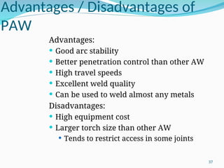
Advantages / Disadvantagesof
PAW
Advantages:
Good arc stability
Better penetration control than other AW
High travel speeds
Excellent weld quality
Can be used to weld almost any metals
Disadvantages:
High equipment cost
Larger torch size than other AW
Tends to restrict access in some joints
37
38.
Resistance Welding (RW)
Agroup of fusion welding processes that use a
combination of heat and pressure to accomplish
coalescence
Heat generated by electrical resistance to current
flow at junction to be welded
Principal RW process is resistance spot welding
(RSW)
38
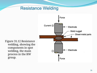
Components in ResistanceSpot
Welding
Parts to be welded (usually sheet metal)
Two opposing electrodes
Means of applying pressure to squeeze parts
between electrodes
Power supply from which a controlled current
can be applied for a specified time duration
40
41.
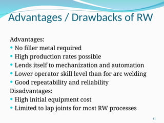
Advantages / Drawbacksof RW
Advantages:
No filler metal required
High production rates possible
Lends itself to mechanization and automation
Lower operator skill level than for arc welding
Good repeatability and reliability
Disadvantages:
High initial equipment cost
Limited to lap joints for most RW processes
41
42.
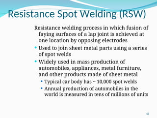
Resistance Spot Welding(RSW)
Resistance welding process in which fusion of
faying surfaces of a lap joint is achieved at
one location by opposing electrodes
Used to join sheet metal parts using a series
of spot welds
Widely used in mass production of
automobiles, appliances, metal furniture,
and other products made of sheet metal
Typical car body has ~ 10,000 spot welds
Annual production of automobiles in the
world is measured in tens of millions of units
42
43.
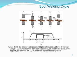
Figure 31.13 (a)Spot welding cycle, (b) plot of squeezing force & current
in cycle (1) parts inserted between electrodes, (2) electrodes close, force
applied, (3) current on, (4) current off, (5) electrodes opened.
Spot Welding Cycle
43
44.
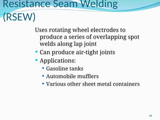
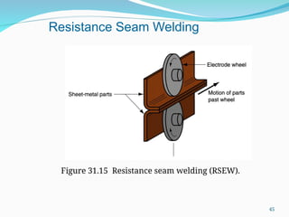
Resistance Seam Welding
(RSEW)
Usesrotating wheel electrodes to
produce a series of overlapping spot
welds along lap joint
Can produce air‑tight joints
Applications:
Gasoline tanks
Automobile mufflers
Various other sheet metal containers
44
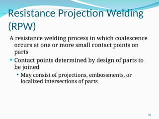
Resistance Projection Welding
(RPW)
Aresistance welding process in which coalescence
occurs at one or more small contact points on
parts
Contact points determined by design of parts to
be joined
May consist of projections, embossments, or
localized intersections of parts
46
47.
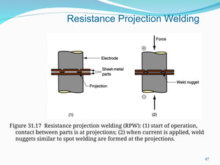
Figure 31.17 Resistanceprojection welding (RPW): (1) start of operation,
contact between parts is at projections; (2) when current is applied, weld
nuggets similar to spot welding are formed at the projections.
Resistance Projection Welding
47
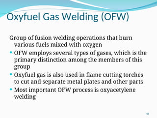
Oxyfuel Gas Welding(OFW)
Group of fusion welding operations that burn
various fuels mixed with oxygen
OFW employs several types of gases, which is the
primary distinction among the members of this
group
Oxyfuel gas is also used in flame cutting torches
to cut and separate metal plates and other parts
Most important OFW process is oxyacetylene
welding
49
50.
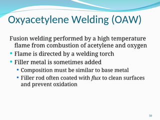
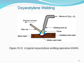
Oxyacetylene Welding (OAW)
Fusionwelding performed by a high temperature
flame from combustion of acetylene and oxygen
Flame is directed by a welding torch
Filler metal is sometimes added
Composition must be similar to base metal
Filler rod often coated with flux to clean surfaces
and prevent oxidation
50
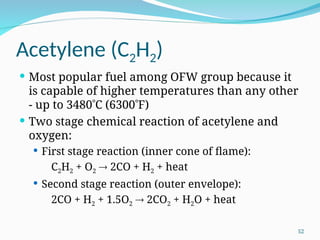
Acetylene (C2H2)
Mostpopular fuel among OFW group because it
is capable of higher temperatures than any other
‑ up to 3480C (6300F)
Two stage chemical reaction of acetylene and
oxygen:
First stage reaction (inner cone of flame):
C2H2 + O2 2CO + H2 + heat
Second stage reaction (outer envelope):
2CO + H2 + 1.5O2 2CO2 + H2O + heat
52
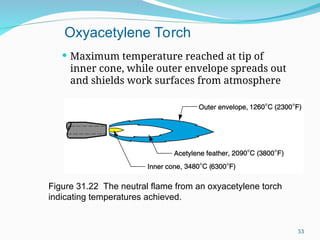
53.
Maximum temperaturereached at tip of
inner cone, while outer envelope spreads out
and shields work surfaces from atmosphere
Figure 31.22 The neutral flame from an oxyacetylene torch
indicating temperatures achieved.
Oxyacetylene Torch
53
54.
Safety Issue inOAW
Together, acetylene and oxygen are highly
flammable
C2H2 is colorless and odorless
It is therefore processed to have characteristic
garlic odor
54
55.
OAW Safety Issue
C2H2 is physically unstable at pressures
much above 15 lb/in2
(about 1 atm)
Storage cylinders are packed with porous
filler material (such as asbestos) saturated
with acetone (CH3COCH3)
Acetone dissolves about 25 times its own
volume of acetylene
Different screw threads are standard on the
C2H2 and O2 cylinders and hoses to avoid
accidental connection of wrong gases
55
56.
Alternative Gases forOFW
Methylacetylene‑Propadiene (MAPP)
Hydrogen
Propylene
Propane
Natural Gas
56
57.
Other Fusion Welding
Processes
FWprocesses that cannot be classified as arc,
resistance, or oxyfuel welding
Use unique technologies to develop heat for
melting
Applications are typically unique
Processes include:
Electron beam welding
Laser beam welding
Electroslag welding
Thermit welding
57
58.
Electron Beam Welding(EBW)
Fusion welding process in which heat for welding
is provided by a highly‑focused, high‑intensity
stream of electrons striking work surface
Electron beam gun operates at:
High voltage (e.g., 10 to 150 kV typical) to
accelerate electrons
Beam currents are low (measured in milliamps)
Power in EBW not exceptional, but power
density is
58
59.
EBW Vacuum Chamber
Whenfirst developed, EBW had to be carried out
in vacuum chamber to minimize disruption of
electron beam by air molecules
Serious inconvenience in production
Pumpdown time can take as long as an hour
59
60.
Three Vacuum Levelsin EBW
High-vacuum welding – welding done in
same vacuum chamber as beam generation
Highest quality weld
Medium-vacuum welding – welding done in
separate chamber with partial vacuum
Vacuum pump-down time reduced
Non-vacuum welding – welding done at or
near atmospheric pressure, with work
positioned close to electron beam generator
Vacuum divider required to separate work
from beam generator
60
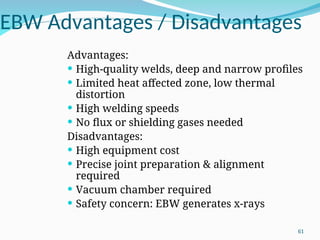
61.
EBW Advantages /Disadvantages
Advantages:
High‑quality welds, deep and narrow profiles
Limited heat affected zone, low thermal
distortion
High welding speeds
No flux or shielding gases needed
Disadvantages:
High equipment cost
Precise joint preparation & alignment
required
Vacuum chamber required
Safety concern: EBW generates x‑rays
61
62.
Laser Beam Welding(LBW)
Fusion welding process in which coalescence is
achieved by energy of a highly concentrated,
coherent light beam focused on joint
Laser = "light amplification by stimulated
emission of radiation"
LBW normally performed with shielding gases to
prevent oxidation
Filler metal not usually added
High power density in small area, so LBW often
used for small parts
62
63.
Comparison: LBW vs.EBW
No vacuum chamber required for LBW
No x‑rays emitted in LBW
Laser beams can be focused and directed by
optical lenses and mirrors
LBW not capable of the deep welds and high
depth‑to‑width ratios of EBW
Maximum LBW depth = ~ 19 mm (3/4 in), whereas
EBW depths = 50 mm (2 in)
63
64.
Thermit Welding (TW)
FWprocess in which heat for coalescence is
produced by superheated molten metal from the
chemical reaction of thermite
Thermite = mixture of Al and Fe3O4 fine powders
that produce an exothermic reaction when
ignited
Also used for incendiary bombs
Filler metal obtained from liquid metal
Process used for joining, but has more in common
with casting than welding
64
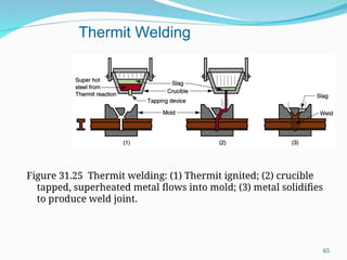
65.
Figure 31.25 Thermitwelding: (1) Thermit ignited; (2) crucible
tapped, superheated metal flows into mold; (3) metal solidifies
to produce weld joint.
Thermit Welding
65
66.
TW Applications
Joiningof railroad rails
Repair of cracks in large steel castings and
forgings
Weld surface is often smooth enough that no
finishing is required
66
67.
Solid State Welding(SSW)
Coalescence of part surfaces is achieved by:
Pressure alone, or
Heat and pressure
If both heat and pressure are used, heat is not
enough to melt work surfaces
For some SSW processes, time is also a factor
No filler metal is added
Each SSW process has its own way of creating a
bond at the faying surfaces
67
68.
Success Factors inSSW
Essential factors for a successful solid state weld
are that the two faying surfaces must be:
Very clean
In very close physical contact with each other to
permit atomic bonding
68
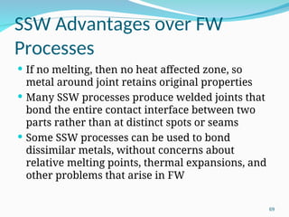
69.
SSW Advantages overFW
Processes
If no melting, then no heat affected zone, so
metal around joint retains original properties
Many SSW processes produce welded joints that
bond the entire contact interface between two
parts rather than at distinct spots or seams
Some SSW processes can be used to bond
dissimilar metals, without concerns about
relative melting points, thermal expansions, and
other problems that arise in FW
69
70.
Solid State WeldingProcesses
Forge welding
Cold welding
Roll welding
Hot pressure welding
Diffusion welding
Explosion welding
Friction welding
Ultrasonic welding
70
71.
Forge Welding
Welding processin which components to be joined
are heated to hot working temperature range
and then forged together by hammering or
similar means
Historic significance in development of
manufacturing technology
Process dates from about 1000 B.C., when
blacksmiths learned to weld two pieces of metal
Of minor commercial importance today except
for its variants
71
72.
Cold Welding (CW)
SSWprocess done by applying high pressure between
clean contacting surfaces at room temperature
Cleaning usually done by degreasing and wire
brushing immediately before joining
No heat is applied, but deformation raises work
temperature
At least one of the metals, preferably both, must be
very ductile
Soft aluminum and copper suited to CW
Applications: making electrical connections
72
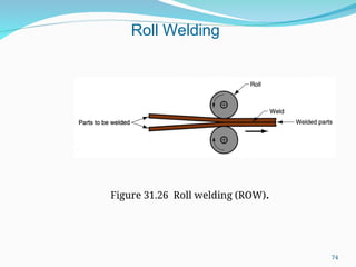
73.
Roll Welding (ROW)
SSWprocess in which pressure sufficient to cause
coalescence is applied by means of rolls, either
with or without external heat
Variation of either forge welding or cold welding,
depending on whether heating of workparts is
done prior to process
If no external heat, called cold roll welding
If heat is supplied, hot roll welding
73
Roll Welding Applications
Cladding stainless steel to mild or low alloy steel
for corrosion resistance
Bimetallic strips for measuring temperature
"Sandwich" coins for U.S mint
75
76.
Diffusion Welding (DFW)
SSWprocess uses heat and pressure, usually in a
controlled atmosphere, with sufficient time for
diffusion and coalescence to occur
Temperatures 0.5 Tm
Plastic deformation at surfaces is minimal
Primary coalescence mechanism is solid state
diffusion
Limitation: time required for diffusion can range
from seconds to hours
76
77.
DFW Applications
Joiningof high‑strength and refractory metals in
aerospace and nuclear industries
Can be used to join either similar and dissimilar
metals
For joining dissimilar metals, a filler layer of
different metal is often sandwiched between
base metals to promote diffusion
77
78.
Explosion Welding (EXW)
SSWprocess in which rapid coalescence of two
metallic surfaces is caused by the energy of a
detonated explosive
No filler metal used
No external heat applied
No diffusion occurs - time is too short
Bonding is metallurgical, combined with
mechanical interlocking that results from a
rippled or wavy interface between the metals
78
79.
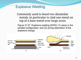
Commonly used tobond two dissimilar
metals, in particular to clad one metal on
top of a base metal over large areas
Figure 31.27 Explosive welding (EXW): (1) setup in the
parallel configuration, and (2) during detonation of the
explosive charge.
Explosive Welding
79
80.
Friction Welding (FRW)
SSWprocess in which coalescence is achieved by
frictional heat combined with pressure
When properly carried out, no melting occurs at
faying surfaces
No filler metal, flux, or shielding gases normally
used
Process yields a narrow HAZ
Can be used to join dissimilar metals
Widely used commercial process, amenable to
automation and mass production
80
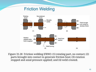
81.
Figure 31.28 Frictionwelding (FRW): (1) rotating part, no contact; (2)
parts brought into contact to generate friction heat; (3) rotation
stopped and axial pressure applied; and (4) weld created.
Friction Welding
81
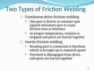
82.
Two Types ofFriction Welding
1. Continuous‑drive friction welding
One part is driven at constant rpm
against stationary part to cause
friction heat at interface
At proper temperature, rotation is
stopped and parts are forced together
2. Inertia friction welding
Rotating part is connected to flywheel,
which is brought up to required speed
Flywheel is disengaged from drive,
and parts are forced together
82
83.
Applications / Limitationsof
FRW
Applications:
Shafts and tubular parts
Industries: automotive, aircraft, farm equipment,
petroleum and natural gas
Limitations:
At least one of the parts must be rotational
Flash must usually be removed
Upsetting reduces the part lengths (which must
be taken into consideration in product design)
83
84.
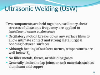
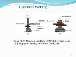
Ultrasonic Welding (USW)
Twocomponents are held together, oscillatory shear
stresses of ultrasonic frequency are applied to
interface to cause coalescence
Oscillatory motion breaks down any surface films to
allow intimate contact and strong metallurgical
bonding between surfaces
Although heating of surfaces occurs, temperatures are
well below Tm
No filler metals, fluxes, or shielding gases
Generally limited to lap joints on soft materials such as
aluminum and copper
84
85.
Figure 31.29 Ultrasonicwelding (USW): (a) general setup
for a lap joint; and (b) close‑up of weld area.
Ultrasonic Welding
85
86.
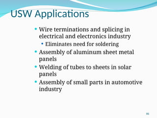
USW Applications
Wireterminations and splicing in
electrical and electronics industry
Eliminates need for soldering
Assembly of aluminum sheet metal
panels
Welding of tubes to sheets in solar
panels
Assembly of small parts in automotive
industry
86
87.
Weld Quality
Concerned withobtaining an acceptable
weld joint that is strong and absent of
defects, and the methods of inspecting
and testing the joint to assure its
quality
Topics:
Residual stresses and distortion
Welding defects
Inspection and testing methods
87
88.
Residual Stresses and
Distortion
Rapid heating and cooling in localized regions
during FW result in thermal expansion and
contraction that cause residual stresses
These stresses, in turn, cause distortion and
warpage
Situation in welding is complicated because:
Heating is very localized
Melting of base metals in these regions
Location of heating and melting is in motion (at
least in AW)
88
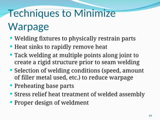
89.
Techniques to Minimize
Warpage
Welding fixtures to physically restrain parts
Heat sinks to rapidly remove heat
Tack welding at multiple points along joint to
create a rigid structure prior to seam welding
Selection of welding conditions (speed, amount
of filler metal used, etc.) to reduce warpage
Preheating base parts
Stress relief heat treatment of welded assembly
Proper design of weldment
89
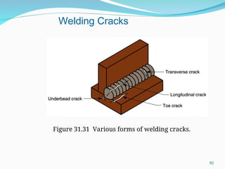
Welding Cracks
Fracture‑type interruptionseither in weld or in
base metal adjacent to weld
Serious defect because it is a discontinuity in the
metal that significantly reduces strength
Caused by embrittlement or low ductility of weld
and/or base metal combined with high restraint
during contraction
In general, this defect must be repaired
91
Cavities
Two defect types,similar to defects found in
castings:
1. Porosity - small voids in weld metal formed by
gases entrapped during solidification
Caused by inclusion of atmospheric gases, sulfur
in weld metal, or surface contaminants
2. Shrinkage voids - cavities formed by shrinkage
during solidification
93
94.
Solid Inclusions
Solidinclusions - nonmetallic material entrapped
in weld metal
Most common form is slag inclusions generated
during AW processes that use flux
Instead of floating to top of weld pool, globules of
slag become encased during solidification
Metallic oxides that form during welding of
certain metals such as aluminum, which
normally has a surface coating of Al2O3
94
95.
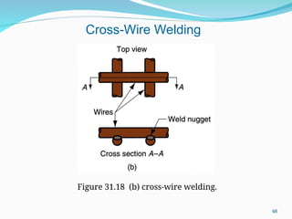
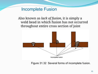
Also known aslack of fusion, it is simply a
weld bead in which fusion has not occurred
throughout entire cross section of joint
Figure 31.32 Several forms of incomplete fusion.
Incomplete Fusion
95
96.
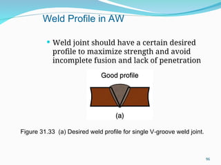
Weld jointshould have a certain desired
profile to maximize strength and avoid
incomplete fusion and lack of penetration
Figure 31.33 (a) Desired weld profile for single V groove weld joint.
‑
Weld Profile in AW
96
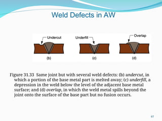
97.
Figure 31.33 Samejoint but with several weld defects: (b) undercut, in
which a portion of the base metal part is melted away; (c) underfill, a
depression in the weld below the level of the adjacent base metal
surface; and (d) overlap, in which the weld metal spills beyond the
joint onto the surface of the base part but no fusion occurs.
Weld Defects in AW
97
Visual Inspection
Mostwidely used welding inspection
method
Human inspector visually examines for:
Conformance to dimensions
Warpage
Cracks, cavities, incomplete fusion, and
other surface defects
Limitations:
Only surface defects are detectable
Welding inspector must also determine
if additional tests are warranted
99
100.
Nondestructive Evaluation (NDE)
Tests Ultrasonic testing - high frequency sound
waves directed through specimen - cracks,
inclusions are detected by loss in sound
transmission
Radiographic testing - x‑rays or gamma
radiation provide photograph of internal
flaws
Dye‑penetrant and fluorescent‑penetrant
tests - methods for detecting small cracks
and cavities that are open at surface
Magnetic particle testing – iron filings
sprinkled on surface reveal subsurface
defects by distorting magnetic field in part
100
101.
Destructive Testing
Tests inwhich weld is destroyed either during
testing or to prepare test specimen
Mechanical tests - purpose is similar to
conventional testing methods such as tensile
tests, shear tests, etc
Metallurgical tests - preparation of metallurgical
specimens (e.g., photomicrographs) of weldment
to examine metallic structure, defects, extent and
condition of heat affected zone, and similar
phenomena
101
102.
Weldability
Capacity of ametal or combination of metals to be
welded into a suitably designed structure, and
for the resulting weld joint(s) to possess the
required metallurgical properties to perform
satisfactorily in intended service
Good weldability characterized by:
Ease with which welding process is accomplished
Absence of weld defects
Acceptable strength, ductility, and toughness in
welded joint
102
103.
Weldability Factors –Welding
Process
Some metals or metal combinations can be
readily welded by one process but are difficult to
weld by others
Example: stainless steel readily welded by most
AW and RW processes, but difficult to weld by
OFW
103
104.
Weldability Factors –Base
Metal Some metals melt too easily; e.g.,
aluminum
Metals with high thermal conductivity
transfer heat away from weld, which
causes problems; e.g., copper
High thermal expansion and contraction
in metal causes distortion problems
Dissimilar metals pose problems in
welding when their physical and/or
mechanical properties are substantially
different
104
105.
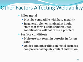
Other Factors AffectingWeldability
Filler metal
Must be compatible with base metal(s)
In general, elements mixed in liquid
state that form a solid solution upon
solidification will not cause a problem
Surface conditions
Moisture can result in porosity in fusion
zone
Oxides and other films on metal surfaces
can prevent adequate contact and fusion
105
106.
Design Considerations in
Welding
Design for welding ‑ product should be designed
from the start as a welded assembly, and not as a
casting or forging or other formed shape
Minimum parts ‑ welded assemblies should
consist of fewest number of parts possible
Example: usually more cost efficient to perform
simple bending operations on a part than to weld
an assembly from flat plates and sheets
106
107.
Arc Welding DesignGuidelines
Good fit‑up of parts - to maintain
dimensional control and minimize
distortion
Machining is sometimes required to
achieve satisfactory fit‑up
Assembly must allow access for welding
gun to reach welding area
Design of assembly should allow flat
welding to be performed as much as
possible, since this is fastest and most
convenient welding position
107
108.
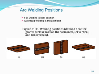
Figure 31.35 Weldingpositions (defined here for
groove welds): (a) flat, (b) horizontal, (c) vertical,
and (d) overhead.
Flat welding is best position
Overhead welding is most difficult
Arc Welding Positions
108
109.
Design Guidelines -RSW
Low‑carbon sheet steel up to 0.125 (3.2 mm) is
ideal metal for RSW 109
How additional strength and stiffness can be
obtained in large flat sheet metal components
Spot welding reinforcing parts into them
Forming flanges and embossments
Spot welded assembly must provide access for
electrodes to reach welding area
Sufficient overlap of sheet metal parts required
for electrode tip to make proper contact
109


![Types%20of%20 Welding[1]](https://cdn.slidesharecdn.com/ss_thumbnails/types20of20welding1-091203225849-phpapp02-thumbnail.jpg?width=640&height=640&fit=bounds)