Download as PDF, PPTX

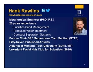
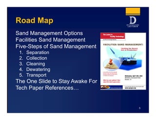
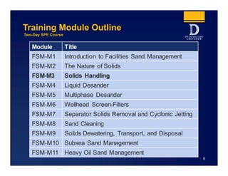

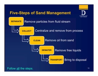
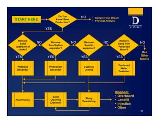
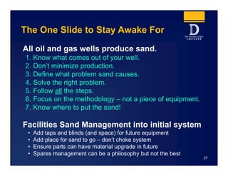


The Distinguished Lecturer Program provides concise summaries of technical documents on facilities sand management. This summary covers a two-day course on the topic presented by Dr. Hank Rawlins, who has over 25 years of industry experience. The course covers the five key steps to managing sand in production facilities: separation, collection, cleaning, dewatering, and transport. It emphasizes understanding sand issues in facilities rather than focusing on specific equipment.


![well_test_lectures__Lo4[1].ppt well testing](https://cdn.slidesharecdn.com/ss_thumbnails/welltestlectureslo41-250203120844-25dfcd18-thumbnail.jpg?width=640&height=640&fit=bounds)


