Download as PDF, PPTX
![EOR Thermal Methods
[Heavy , viscous crude]
Target : Increase reservoir temperature
of the oil and reduce its viscosity.](https://image.slidesharecdn.com/3-eor3thermal-180113184235/75/thermal-methods-for-eor-recovery-1-2048.jpg)

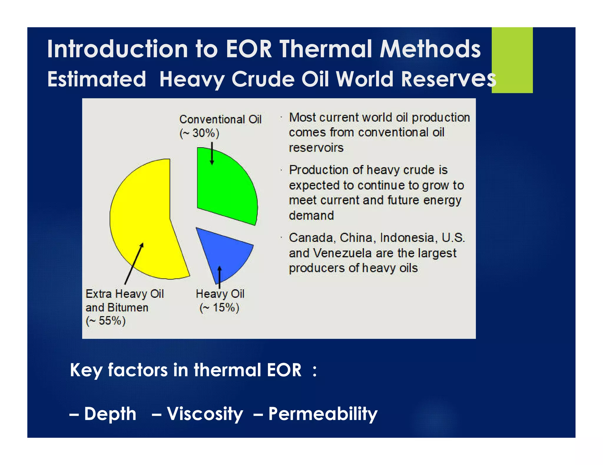


This document provides an overview of thermal enhanced oil recovery (EOR) methods for heavy oils. It discusses the basic mechanisms and screening criteria for steam injection, steam assisted gravity drainage (SAGD), hot water flooding, and combustion methods like in-situ combustion (ISC) and high pressure air injection (HPAI). Case studies on SAGD and HPAI are presented. Thermal EOR aims to increase reservoir temperature and reduce oil viscosity for improved production rates. Proper screening of reservoir properties like depth, viscosity, permeability is required to select the optimal thermal method.


