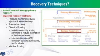
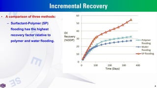
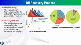
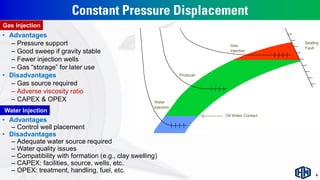
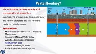
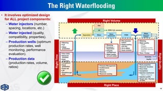
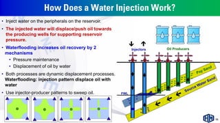
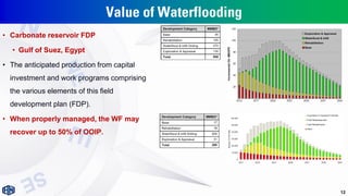
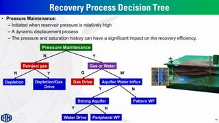
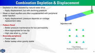
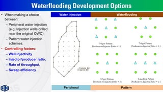
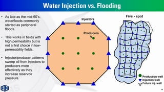
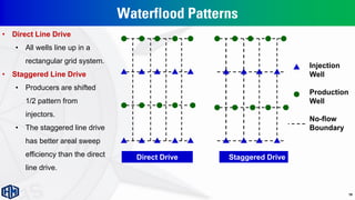
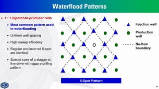
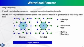
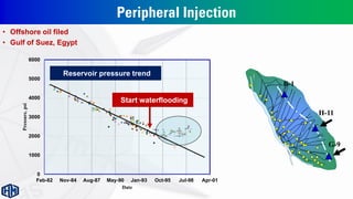
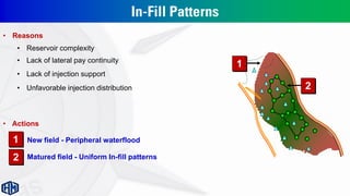
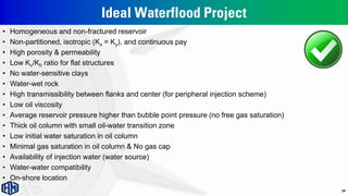
Oil Recovery Techniques
Part of “Advanced Waterflooding” Course
For Kuwait Oil Company (KOC), Kuwait
2022
1
Hesham Mokhtar Ali
Senior Reservoir Engineer
in/heshammokhtarali/
Drainage Cut-of fs
Sw eep
Pore scale
ef ficiency
Ab ility to
displace oil/gas
Capture of mobile
hydrocarbons b y w ells
C onnection of
w ells to oil/gas
Physical & commercial cons train ts
Eps Es
*
*
* Ed Ec
Areal Vert ica l Re servoir
e nergy
Facilitie s Commercia l
* * *
Rock /fl ui d type
Recov ery process
Compart ments W ell
type/spacing
Recovery proc ess;
Kv/Kh; Di p, Kx/Ky
Aqui fer influx;
i njection;
expansivity
WO R; G O R;
facilities desi gn
L icense terms;
export l imits
=
RF
Recovery Process:
waterflood, EOR
Well-work: Offtake
management by
zones, layers
The Recovery Process
Pore Scale Efficiency Drainage Sweep Efficiency Cut-offs
Recovery
Efficiency
• For the full system, the recovery efficiency can be very complicated.
• Therefore, the reservoir simulation introduces a significant tool for understanding reservoir dynamics
Drilling: Infill, Non-
Conventional Wells,
peripheral or in-field pools
Sustain Rate: Reservoir Energy
(Injection, Artificial Lift,
Compression), Facilities
upgrades
Recovery Techniques?
• Natural reservoir energy (primary
recovery)
• Improved recovery methods:
• Pressure maintenance (Gas
injection & Waterflooding)
• Thermal recovery
• Chemical flooding
– Mobility control by adding
polymers to reduce the mobility
of the injected water,
– Interfacial tension (IFT)
reduction by using surfactants,
and/or alkalis.
• Miscible flooding
Incremental Recovery
• A comparison of three methods:
– Surfactant-Polymer (SP)
flooding has the highest
recovery factor relative to
polymer and water flooding.
4
Oil Recovery Process
• Primary recovery:
– The production of
hydrocarbons under the
natural driving mechanisms
present in the reservoir.
• Secondary recovery:
– The additional recovery
resulting from the
conventional methods of
water injection and
immiscible gas injection.
Target for different crude oil systems
Oil recovery categories
Constant Pressure Displacement
• Advantages
– Control well placement
• Disadvantages
– Adequate water source required
– Water quality issues
– Compatibility with formation (e.g., clay swelling)
– CAPEX: facilities, source, wells, etc.
– OPEX: treatment, handling, fuel, etc.
• Advantages
– Pressure support
– Good sweep if gravity stable
– Fewer injection wells
– Gas “storage” for later use
• Disadvantages
– Gas source required
– Adverse viscosity ratio
– CAPEX & OPEX
Water Injection
Gas Injection
6
Typical Production Performance
• For many fields, especially smaller ones, the plateau phase can be very short, while large fields can stay
several decades at the plateau production level.
First Oil
Decline
Peak Oil Plateau
Prod. BU
Discovery
Abandonment (EUR)
Further Explorations
Maximizing The Asset Value
 Techniques to identify opportunities:
 Well interventions: acid jobs, squeezes, recompletions, re-fracturing jobs
 Wells to shut in or re-activate
 Improved waterflood management
 Goal: Improve production/recovery efficiency.
4
3
2
1
Payout time
Cumulative production
Extend field lifetime
Oilfield Development Operations
8
Waterflooding has a
significant rule for
increasing the UR.
Waterflooding?
• It is a secondary recovery technique of
increasing the oil production.
• Over time, the pressure in an oil reservoir slowly
and steadily decreases and as a result the
production rate decreases.
• Applications:
– Maintain Reservoir Pressure – Pressure
Maintenance
– Supplement Natural Water Influx
– Waterflood dominates processes
– Relatively low cost
– General availability of water
– Ease of application water injection
9
The Right Waterflooding
• It involves optimized design
for ALL project components:
– Water injectors (number,
spacing, locations, etc.)
– Water injected (quality,
compatibility, properties).
– Production wells (optimum
production rates, well
monitoring, performance
evaluation).
– Production data
(production rates, volume,
ratios)
10
Right Volume
Right Place
Right
Quality
Right
Time
How Does a Water Injection Work?
• Inject water on the peripherals on the reservoir.
• The injected water will displace/push oil towards
the producing wells for supporting reservoir
pressure.
• Waterflooding increases oil recovery by 2
mechanisms
• Pressure maintenance
• Displacement of oil by water
• Both processes are dynamic displacement processes.
Waterflooding: injection pattern displace oil with
water
• Use injector-producer patterns to sweep oil. FWL
Injectors Oil Producers
11
Value of Waterflooding
• Carbonate reservoir FDP
• Gulf of Suez, Egypt
• The anticipated production from capital
investment and work programs comprising
the various elements of this field
development plan (FDP).
• When properly managed, the WF may
recover up to 50% of OOIP.
12
Recovery Process Decision Tree
Pressure Maintenance
Reinject gas Gas or Water
Depletion Depletion/Gas
Drive
Gas Drive Aquifer Water Influx
Water Drive
Strong Aquifer
Peripheral WF
Pattern WF
Y
N
Y
N W
G
N
Y
N
Y
• Pressure Maintenance:
– Initiated when reservoir pressure is relatively high
– A dynamic displacement process
– The pressure and saturation history can have a significant impact on the recovery efficiency.
13
Combination Depletion & Displacement
• Depletion is often assisted by natural water drive
– Apply displacement, but with declining pressure
• Weak or dead aquifers are often supplemented with peripheral
water injection
– Apply displacement; pressure depends on voidage
replacement rates
Injection well
• Pattern flood
– Better pressure maintenance for low permeability
– More appropriate for low dip
– High rate when qcrit is low
• Downdip peripheral
– Fewer wells
– Better sweep when gravity stable
14
Waterflooding Development Options
• When making a choice
between:
– Peripheral water injection
(e.g. Injection wells drilled
near the original OWC)
– Pattern water injection
schemes.
• Controlling factors:
– Well injectivity
– Injector/producer ratio,
– Rate of throughput,
– Sweep efficiency
Peripheral 15
Water injection Waterflooding
Pattern
Waterflood Patterns
 Peripheral (at the edge or periphery of the reservoir)
• Advantages: Better areal sweep, increase displacement efficiency,
for partial water drive reservoir, delayed water Breakthrough
• Disadvantage: The response to the water injection is limited to the
producers, delayed field respond
• Uses: in smaller reservoirs or combination with pattern
 Pattern (irregular and regular repeating patterns)
• Advantages: Faster fill-up and pressurization, Faster field
response to flood, High sweep efficiency
• Disadvantage: High investment, Early water BT, Adverse MR
16
Peripheral vs. Pattern
• Peripheral (bottom up) flood may be preferable:
• Relatively thick reservoirs with good vertical communication
• Reservoirs with high dip
• Water injection near the original OWC
– Supplementation of peripheral injection with infield/pattern injectors may also be required in case of
• Relatively low permeability
• Significant lateral distance between injectors & producers (inadequate support at crestal
producers).
• Pattern water injection is best suited for
• Reservoirs with poor vertical communication (little advantage from oil/water gravity segregation).
– The optimal flood patterns (5-spot, 7-spot, 9-spot patterns, etc.) are a function of:
• Fault patterns
• Areal heterogeneity
• Reservoir anisotropy
• Mobility ratio
17
Water Injection vs. Flooding
Five - spot
Production well
Injection well
Future inj. well
Injectors
Producers
18
• As late as the mid-60’s,
waterfloods commonly
started as peripheral
floods.
• This works in fields with
high permeability but is
not a first choice in low-
permeability fields.
• Injector/producer patterns
sweep oil from injectors to
producers more
effectively as they
increase reservoir
pressure.
Waterflood Patterns
Direct Drive Staggered Drive
Injection
Well
Production
Well
No-flow
Boundary
• Direct Line Drive
• All wells line up in a
rectangular grid system.
• Staggered Line Drive
• Producers are shifted
1/2 pattern from
injectors.
• The staggered line drive
has better areal sweep
efficiency than the direct
line drive.
19
Waterflood Patterns
Injection well
Production
well
No-flow
boundary
 1 : 1 injector-to-producer ratio
 Most common pattern used
in waterflooding
 Uniform well spacing
 High sweep efficiency
 Regular and inverted 5-spot
are identical
 Special case of a staggered
line drive with square drilling
pattern
20
5-Spot Pattern
Waterflood Patterns
Inverted
Normal
Injection
Well
Production
Well
No-flow
Boundary
 Irregular spacing
 If used, inverted pattern preferred - has more production than injection wells
 May be used for pilot floods in normal pattern form because it results in good control of flow during a test
flood
21
7-Spot Pattern
B-1
H-11
G-9
Peripheral Injection
0
1000
2000
3000
4000
5000
6000
Feb-82 Nov-84 Aug-87 May-90 Jan-93 Oct-95 Jul-98 Apr-01
Pressure,
psi
Date
Start waterflooding
• Offshore oil filed
• Gulf of Suez, Egypt
Reservoir pressure trend
In-Fill Patterns
• Reasons
• Reservoir complexity
• Lack of lateral pay continuity
• Unfavorable injection distribution
• Lack of injection support
• Actions
• Matured field - Uniform In-fill patterns
• New field - Peripheral waterflood
2
2
1
1
Ideal Waterflood Project
• Homogeneous and non-fractured reservoir
• Non-partitioned, isotropic (Kx = Ky), and continuous pay
• High porosity & permeability
• Low Kv/Kh ratio for flat structures
• No water-sensitive clays
• Water-wet rock
• High transmissibility between flanks and center (for peripheral injection scheme)
• Low oil viscosity
• Average reservoir pressure higher than bubble point pressure (no free gas saturation)
• Thick oil column with small oil-water transition zone
• Low initial water saturation in oil column
• Minimal gas saturation in oil column & No gas cap
• Availability of injection water (water source)
• Water-water compatibility
• On-shore location
24
Hesham Mokhtar
Hesham Mokhtar
Hesham
Mokhtar
Hesham
Mokhtar
Hesham
Mokhtar
Hesham Mokhtar

Recovery_techniques__1674919213.pdf

  • 1.
    Oil Recovery Techniques Partof “Advanced Waterflooding” Course For Kuwait Oil Company (KOC), Kuwait 2022 1 Hesham Mokhtar Ali Senior Reservoir Engineer in/heshammokhtarali/
  • 2.
    Drainage Cut-of fs Sweep Pore scale ef ficiency Ab ility to displace oil/gas Capture of mobile hydrocarbons b y w ells C onnection of w ells to oil/gas Physical & commercial cons train ts Eps Es * * * Ed Ec Areal Vert ica l Re servoir e nergy Facilitie s Commercia l * * * Rock /fl ui d type Recov ery process Compart ments W ell type/spacing Recovery proc ess; Kv/Kh; Di p, Kx/Ky Aqui fer influx; i njection; expansivity WO R; G O R; facilities desi gn L icense terms; export l imits = RF Recovery Process: waterflood, EOR Well-work: Offtake management by zones, layers The Recovery Process Pore Scale Efficiency Drainage Sweep Efficiency Cut-offs Recovery Efficiency • For the full system, the recovery efficiency can be very complicated. • Therefore, the reservoir simulation introduces a significant tool for understanding reservoir dynamics Drilling: Infill, Non- Conventional Wells, peripheral or in-field pools Sustain Rate: Reservoir Energy (Injection, Artificial Lift, Compression), Facilities upgrades
  • 3.
    Recovery Techniques? • Naturalreservoir energy (primary recovery) • Improved recovery methods: • Pressure maintenance (Gas injection & Waterflooding) • Thermal recovery • Chemical flooding – Mobility control by adding polymers to reduce the mobility of the injected water, – Interfacial tension (IFT) reduction by using surfactants, and/or alkalis. • Miscible flooding
  • 4.
    Incremental Recovery • Acomparison of three methods: – Surfactant-Polymer (SP) flooding has the highest recovery factor relative to polymer and water flooding. 4
  • 5.
    Oil Recovery Process •Primary recovery: – The production of hydrocarbons under the natural driving mechanisms present in the reservoir. • Secondary recovery: – The additional recovery resulting from the conventional methods of water injection and immiscible gas injection. Target for different crude oil systems Oil recovery categories
  • 6.
    Constant Pressure Displacement •Advantages – Control well placement • Disadvantages – Adequate water source required – Water quality issues – Compatibility with formation (e.g., clay swelling) – CAPEX: facilities, source, wells, etc. – OPEX: treatment, handling, fuel, etc. • Advantages – Pressure support – Good sweep if gravity stable – Fewer injection wells – Gas “storage” for later use • Disadvantages – Gas source required – Adverse viscosity ratio – CAPEX & OPEX Water Injection Gas Injection 6
  • 7.
    Typical Production Performance •For many fields, especially smaller ones, the plateau phase can be very short, while large fields can stay several decades at the plateau production level. First Oil Decline Peak Oil Plateau Prod. BU Discovery Abandonment (EUR) Further Explorations
  • 8.
    Maximizing The AssetValue  Techniques to identify opportunities:  Well interventions: acid jobs, squeezes, recompletions, re-fracturing jobs  Wells to shut in or re-activate  Improved waterflood management  Goal: Improve production/recovery efficiency. 4 3 2 1 Payout time Cumulative production Extend field lifetime Oilfield Development Operations 8 Waterflooding has a significant rule for increasing the UR.
  • 9.
    Waterflooding? • It isa secondary recovery technique of increasing the oil production. • Over time, the pressure in an oil reservoir slowly and steadily decreases and as a result the production rate decreases. • Applications: – Maintain Reservoir Pressure – Pressure Maintenance – Supplement Natural Water Influx – Waterflood dominates processes – Relatively low cost – General availability of water – Ease of application water injection 9
  • 10.
    The Right Waterflooding •It involves optimized design for ALL project components: – Water injectors (number, spacing, locations, etc.) – Water injected (quality, compatibility, properties). – Production wells (optimum production rates, well monitoring, performance evaluation). – Production data (production rates, volume, ratios) 10 Right Volume Right Place Right Quality Right Time
  • 11.
    How Does aWater Injection Work? • Inject water on the peripherals on the reservoir. • The injected water will displace/push oil towards the producing wells for supporting reservoir pressure. • Waterflooding increases oil recovery by 2 mechanisms • Pressure maintenance • Displacement of oil by water • Both processes are dynamic displacement processes. Waterflooding: injection pattern displace oil with water • Use injector-producer patterns to sweep oil. FWL Injectors Oil Producers 11
  • 12.
    Value of Waterflooding •Carbonate reservoir FDP • Gulf of Suez, Egypt • The anticipated production from capital investment and work programs comprising the various elements of this field development plan (FDP). • When properly managed, the WF may recover up to 50% of OOIP. 12
  • 13.
    Recovery Process DecisionTree Pressure Maintenance Reinject gas Gas or Water Depletion Depletion/Gas Drive Gas Drive Aquifer Water Influx Water Drive Strong Aquifer Peripheral WF Pattern WF Y N Y N W G N Y N Y • Pressure Maintenance: – Initiated when reservoir pressure is relatively high – A dynamic displacement process – The pressure and saturation history can have a significant impact on the recovery efficiency. 13
  • 14.
    Combination Depletion &Displacement • Depletion is often assisted by natural water drive – Apply displacement, but with declining pressure • Weak or dead aquifers are often supplemented with peripheral water injection – Apply displacement; pressure depends on voidage replacement rates Injection well • Pattern flood – Better pressure maintenance for low permeability – More appropriate for low dip – High rate when qcrit is low • Downdip peripheral – Fewer wells – Better sweep when gravity stable 14
  • 15.
    Waterflooding Development Options •When making a choice between: – Peripheral water injection (e.g. Injection wells drilled near the original OWC) – Pattern water injection schemes. • Controlling factors: – Well injectivity – Injector/producer ratio, – Rate of throughput, – Sweep efficiency Peripheral 15 Water injection Waterflooding Pattern
  • 16.
    Waterflood Patterns  Peripheral(at the edge or periphery of the reservoir) • Advantages: Better areal sweep, increase displacement efficiency, for partial water drive reservoir, delayed water Breakthrough • Disadvantage: The response to the water injection is limited to the producers, delayed field respond • Uses: in smaller reservoirs or combination with pattern  Pattern (irregular and regular repeating patterns) • Advantages: Faster fill-up and pressurization, Faster field response to flood, High sweep efficiency • Disadvantage: High investment, Early water BT, Adverse MR 16
  • 17.
    Peripheral vs. Pattern •Peripheral (bottom up) flood may be preferable: • Relatively thick reservoirs with good vertical communication • Reservoirs with high dip • Water injection near the original OWC – Supplementation of peripheral injection with infield/pattern injectors may also be required in case of • Relatively low permeability • Significant lateral distance between injectors & producers (inadequate support at crestal producers). • Pattern water injection is best suited for • Reservoirs with poor vertical communication (little advantage from oil/water gravity segregation). – The optimal flood patterns (5-spot, 7-spot, 9-spot patterns, etc.) are a function of: • Fault patterns • Areal heterogeneity • Reservoir anisotropy • Mobility ratio 17
  • 18.
    Water Injection vs.Flooding Five - spot Production well Injection well Future inj. well Injectors Producers 18 • As late as the mid-60’s, waterfloods commonly started as peripheral floods. • This works in fields with high permeability but is not a first choice in low- permeability fields. • Injector/producer patterns sweep oil from injectors to producers more effectively as they increase reservoir pressure.
  • 19.
    Waterflood Patterns Direct DriveStaggered Drive Injection Well Production Well No-flow Boundary • Direct Line Drive • All wells line up in a rectangular grid system. • Staggered Line Drive • Producers are shifted 1/2 pattern from injectors. • The staggered line drive has better areal sweep efficiency than the direct line drive. 19
  • 20.
    Waterflood Patterns Injection well Production well No-flow boundary 1 : 1 injector-to-producer ratio  Most common pattern used in waterflooding  Uniform well spacing  High sweep efficiency  Regular and inverted 5-spot are identical  Special case of a staggered line drive with square drilling pattern 20 5-Spot Pattern
  • 21.
    Waterflood Patterns Inverted Normal Injection Well Production Well No-flow Boundary  Irregularspacing  If used, inverted pattern preferred - has more production than injection wells  May be used for pilot floods in normal pattern form because it results in good control of flow during a test flood 21 7-Spot Pattern
  • 22.
    B-1 H-11 G-9 Peripheral Injection 0 1000 2000 3000 4000 5000 6000 Feb-82 Nov-84Aug-87 May-90 Jan-93 Oct-95 Jul-98 Apr-01 Pressure, psi Date Start waterflooding • Offshore oil filed • Gulf of Suez, Egypt Reservoir pressure trend
  • 23.
    In-Fill Patterns • Reasons •Reservoir complexity • Lack of lateral pay continuity • Unfavorable injection distribution • Lack of injection support • Actions • Matured field - Uniform In-fill patterns • New field - Peripheral waterflood 2 2 1 1
  • 24.
    Ideal Waterflood Project •Homogeneous and non-fractured reservoir • Non-partitioned, isotropic (Kx = Ky), and continuous pay • High porosity & permeability • Low Kv/Kh ratio for flat structures • No water-sensitive clays • Water-wet rock • High transmissibility between flanks and center (for peripheral injection scheme) • Low oil viscosity • Average reservoir pressure higher than bubble point pressure (no free gas saturation) • Thick oil column with small oil-water transition zone • Low initial water saturation in oil column • Minimal gas saturation in oil column & No gas cap • Availability of injection water (water source) • Water-water compatibility • On-shore location 24
  • 25.