Download as PDF, PPTX


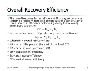
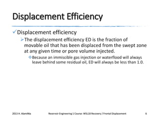
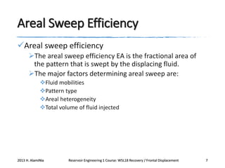
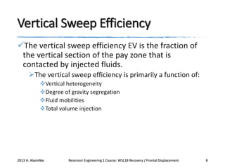
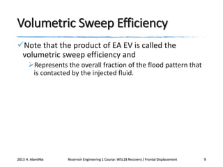
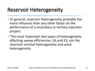


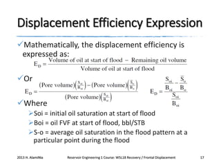
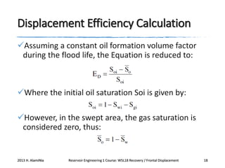
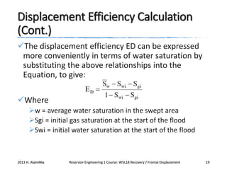
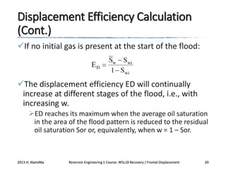


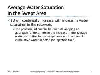


This document provides an overview of reservoir engineering concepts related to oil recovery from waterflooding. It discusses that the overall recovery efficiency from waterflooding is calculated as the product of displacement efficiency, areal sweep efficiency, and vertical sweep efficiency. Displacement efficiency refers to the fraction of movable oil recovered from the swept region. Areal and vertical sweep efficiencies refer to the fractional area and vertical section of the reservoir that is contacted by the injected water. The document also examines factors that influence sweep efficiencies such as reservoir heterogeneity, mobility ratio, flooding pattern, and injection volume.


![Heinemann zoltán e[1]._-_petroleum_recovery_](https://cdn.slidesharecdn.com/ss_thumbnails/heinemannzoltne1-150111210400-conversion-gate02-thumbnail.jpg?width=640&height=640&fit=bounds)


![Heinemann zoltán e[1]._-_petroleum_recovery_](https://cdn.slidesharecdn.com/ss_thumbnails/heinemannzoltne1-150111211406-conversion-gate02-thumbnail.jpg?width=640&height=640&fit=bounds)