Download as PDF, PPTX

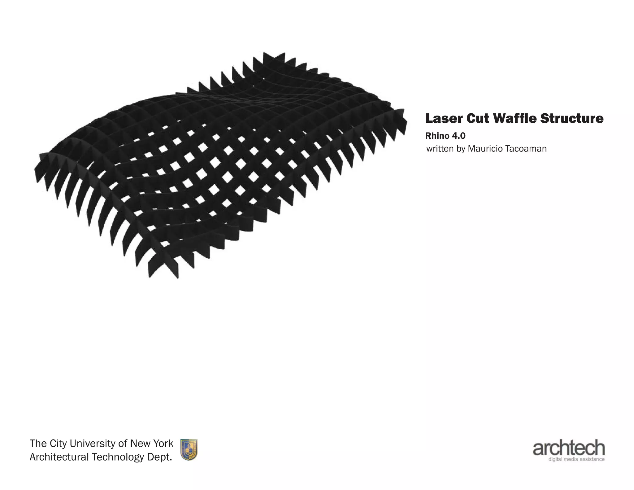
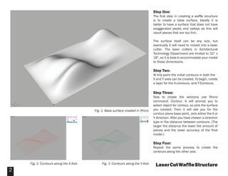
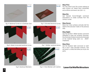

The document provides step-by-step instructions for creating a waffle structure that can be laser cut. It involves: 1) Creating a base surface in Rhino, then adding X and Y contours using the Contour command at set distances. 2) Extruding the contour curves to create surfaces, then offsetting the surfaces to add thickness. 3) Using Boolean split to cut slots into the pieces so they can be joined. 4) Separating the X and Y axis pieces, labeling them, and arranging them within the laser cutter bed size.