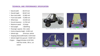
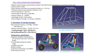
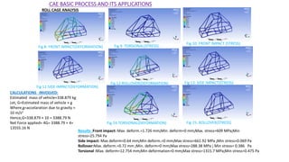
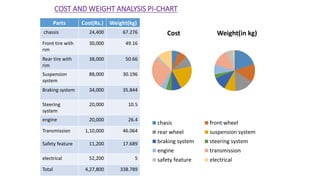
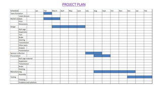
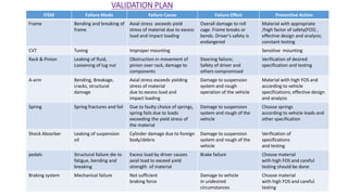
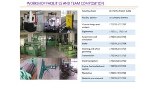
Virtual BAJA SAEINDIA 2016
TEAM BRAHMAPUTRA
TEZPUR UNIVERSITY
TEAM ID-17227
TECHNICAL AND PERFORMANCE SPECIFICATION
• Overall width : 60.575 inch
• Overall length : 85.817 inch
• Rear track width : 52.482 inch
• Front track width : 52.482 inch
• Wheel base : 62.243 inch
• Ground clearance : 11.762 inch
• Maximum speed : 41 kmph
• Kerb weight : 338.879 kg
• Passenger capacity : One seater
• Centre of gravity height : 13.855 inch
• Vehicle type : All terrain vehicle
• Stopping distance(40 kmph): 13.04 meter
• Vehicle height from ground : 54.607 inch
• Engine : Briggs & Stratton 10 HP OHV
Intek four stroke , 305 cc , air
cooled
Fig 2: VIEW FROM BACKFig 1: ISOMETRIC VIEW
Fig 3: SIDE VIEW Fig 4: FRONT VIEW
ROLL CAGE DESIGN AND ERGONOMICS
• Material used for primary and secondary members: AISI 4130 Chromium Molybdenum cold rolled seamless tube
• Carbon content: 0.30%
• Outer diameter of primary and secondary members, D0 = 25.4 mm
• Thickness of primary and secondary members: 3 mm
• Internal diameter, Di = 19.4 mm
• Yield strength of AISI 4130, Sy=460 MPa
• Young’s modulus, Ex = 205GPa
• Total length of tube = 38.43 metres
• Overall weight of roll cage = 41.314 kg ≈ 412.996 N
1> Calculation for Bending Strength :
Polar moment of inertia, I= 3.14*(D0
4 - Di
4)/64 =
13471.805 mm4
Distance to extreme fiber, c = 25.4/2 = 12.7 mm
∴ Bending Strength = SyI/c = 487.955 N-m
And, Bending Stiffness=ExI = 2761.720 N-m2
2>Ergonomics specification:
a) Spacious enough to accommodate a
95th percentile male and 5th percentile
female
b) Comfortable seating and viewing
angle.
c) Suitable reach limit
d) Better visibility
e) Clearance requirements are fulfilled
f) Easy entrance and exit.
Fig 5: ROLL CAGE DESIGN
Fig 6: ERGONOMICS- LATERAL CLEARANCEFig 7:ERGONOMICS- HEAD CLEARANCE
CAE BASIC PROCESS AND ITS APPLICATIONS
Fig 10: FRONT IMPACT (STRESS)
Fig 13: SIDE IMPACT(STRESS)
Fig 15: ROLLOVER(STRESS)
Fig 9: TORSIONAL(STRESS)
CALCULATIONS INVOLVED:
Estimated mass of vehicle=338.879 kg
Let, G=Estimated mass of vehicle × g
Where,g=accelaration due to gravity ≈
10 m/s2
Hence,G=338.879 × 10 = 3388.79 N
Net Force applied= 4G= 3388.79 × 4=
13555.16 N
ROLL CAGE ANALYSIS
Fig 8: FRONT IMPACT(DEFORMATION)
Fig 11:SIDE IMPACT(DEFORMATION)
Fig 12:ROLLOVER(DEFORMATION)
Fig 14:TORSIONAL(DEFORMATION)
Results :Front impact: Max. deform.=1.726 mm;Min. deform=0 mm;Max. stress=609 MPa;Min
stress=25.794 Pa
Side impact: Max deform=0.64 mm;Min deform.=0 mm;Max stress=661.92 MPa ;Min stress=0.069 Pa
Rollover:Max. deform.=0.72 mm ;Min. deform=0 mm;Max stress=288.38 MPa ; Min stress= 0.386 Pa
Torsional :Max. deform=12.754 mm;Min deformation=0 mm;Max stress=1315.7 MPa;Min stress=0.475 Pa
SUSPENSION
PARAMETER FRONT REAR
Suspension type Double Wishbones
Suspension material AISI 4130
Natural frequency 2.09 Hz 2.35 Hz
Spring Stiffness 16.11N/mm
Spring material STEEL 17-7 A313
Motion Ratio 0.491
Damper Ratio 0.35
Max. Suspension Travel 135 mm 220 mm
Bounce Frequency 1.60 Hz
Caster (deg.) 7.0 (+ve)
Camber (deg.) 0-0.5(+ ve)
Kingpin Inclination (deg.) 9.37
Toe (deg.) 0
Sprung Mass 338.879 Kg
Un –Sprung Mass 48 Kg
Toppling Speed
(at min. turning radius)
20.16 Km/h
Roll Centre Height 195.834 mm 225 mm
KNUCKLE STRESS ANALYSYS
EXPLODED VIEW
ASSEMBLY
HUB STRESS ANALYSYS
A-ARM STRESS ANLYSIS
Camber angle v/s Wheel
Travel
Roll Centre Height v/s
Wheel Travel
Camber v/s Steer S
• Hydraulically actuated disc brake on all four
wheels lock simultaneously
• Tandem master cylinder
• 2POT floating calliper
• X-split braking system
• Pedal ratio = 6:1
• Pedal force = 120 N
• Brake fluid = DOT4
BRAKES
Parts Specification
Rotor(stainless
Steel)
Polaris
sportsman500
O.D -- 9”
I.D – 5.5”
Master cylinder
(tandem)
Polaris
sportsman 500
0.75”
Calliper cylinder
( 2pot)
Polaris
sportsman500
1”
Performance Value
Torque per wheel 93.72 Nm
Total brake force 1283.39 N
Deceleration 4.73 m/s2
Stopping distance 13.04 m
Wt. transfer 36%
Disc brake and calliper
assembly
Dynamic wt. On front
axel
2258.29 N
Dynamic wt. On rear axel 1062.73 N
STEERING AND WHEEL GEOMETRY
PARAMETER VALUES
TYPE RACK & PINION
INSIDE WHEEL ANGLE 45 degree
OUTSIDE WHEEL ANGLE 28.48 degree
ACKERMANN ANGLE 39.75 degree
WHEEL BASE 62.243 inch.
TRACK WIDTH 52.482 inch.
TURNING RADIUS 3.31 m
RACK LENGTH 16 inch.
RACK TRAVEL(lock to
lock)
6.5 inch.
End to end 390 degree
ACKERMANN
PERCENTAGE
72.48 %
STEERING RATIO 8.4 : 1
TORQUE 4.05 N-m
INSIDE WHEEL ANGLE
FOR 100% ACKERMANN
22.79
Item Description &
Dimensions
Front tire Carlisle AT489 -
25 x 8-12
Rear tire Carlisle AT489 -
25 x 11-12
Ackermann Geometry
Steering system
Wheel assembly
RPM
(Engi
ne)
Engine
Torque
(Nm)
Total
Gear
Ratio
Torque
on Wheel
(Nm)
Traction
(N)
Velocity
(km/hr)
Resistive
forces
(N)
Accele
ration
(m/s2)
1800 18.03 39.90 633.07 1993.92 5.40 443.81 3.43
2000 18.71 36.69 604.10 1902.66 6.52 444.03 3.23
2200 18.98 33.50 559.53 1762.30 7.86 444.37 2.92
2400 19.32 30.30 515.15 1622.52 9.48 444.85 2.61
2600 19.52 27.09 465.34 1465.64 11.48 445.59 2.26
2800 19.67 23.94 414.40 1305.17 14.01 446.70 1.90
3000 19.60 20.70 357.03 1124.52 19.96 448.28 1.50
3200 19.38 17.50 298.50 940.01 21.89 451.61 1.08
3400 19.11 14.29 240.31 756.88 28.48 457.35 0.66
3600 18.84 11.09 183.86 579.09 38.84 469.40 0.24
3800 18.11 11.09 176.74 556.66 41.01 472.43 0.19
POWERTRAIN
Engine specifications
Briggs and Stratton 10 HP OHV Intek
Displacement : 305cc
Max Power : 7.187 kW @ 3800 rpm
Max Torque : 19.66 Nm @ 2810 rpm
Transmission Unit
Polaris P90 belt CVT
Primary(input) : 184 mm
Secondary(o/p): 241 mm
Low ratio :: 3.83:1
High ratio :: 0.76:1
Reversing Mechanism Tire Size (25’’*8”*13”)
Powertrain Layout
ENGINE
(Crankshaft)
Reversing
mechanism
(Engaged/Dise
ngaged)
CVT
SPROCKET-1
(2:1)
SPROCKET-2
(2.625:1)
LIMITED SLIP
DIFFERENTIAL
(Final Drive:
3.16)
WHEELS
TABLE: VELOCITY AND ACCELERATION AT OUTPUT
COST AND WEIGHT ANALYSIS PI-CHART
Parts Cost(Rs.) Weight(kg)
chassis 24,400 67.276
Front tire with
rim
30,000 49.16
Rear tire with
rim
38,000 50.66
Suspension
system
88,000 30.196
Braking system 34,000 35.844
Steering
system
20,000 10.5
engine 20,000 26.4
Transmission 1,10,000 46.064
Safety feature 11,200 17.689
electrical 52,200 5
Total 4,27,800 338.789
Cost
chasis front wheel
rear wheel suspension system
braking system steering system
engine transmission
safety feature electrical
Weight(in kg)
PROJECT PLAN
VALIDATION PLAN
ITEM Failure Mode Failure Cause Failure Effect Preventive Action
Frame Bending and breaking of
frame
Axial stress exceeds yield
stress of material due to excess
load and impact loading
Overall damage to roll
cage. Frame breaks or
bends. Driver’s safety is
endangered
Material with appropriate
/high factor of safety(FOS) ,
effective design and analysis;
constant testing
CVT Tuning Improper mounting Sensitive mounting
Rack & Pinion Leaking of fluid,
Loosening of lug nut
Obstruction in movement of
pinion over rack, damage to
components
Steering failure;
Safety of driver and
others compromised
Verification of desired
specification and testing
A-arm Bending, Breakage,
cracks, structural
damage
Axial stress exceeds yielding
stress of material
due to excess load and
impact loading
Damage to suspension
system and rough
operation of the vehicle
Material with high FOS and
according to vehicle
specifications; effective design
and analysis
Spring Spring fractures and fail Due to faulty choice of springs,
spring fails due to loads
exceeding the yield stress of
the material
Damage to suspension
system and rough of the
vehicle
Choose springs
according to vehicle loads and
other specification
Shock Absorber Leaking of suspension
oil
Cylinder damage due to foreign
body/debris
Damage to suspension
system and rough of the
vehicle
Verification of
specifications
and testing
pedals Structural failure die to
fatigue, bending and
breaking
Excess load by driver causes
axial load to exceed yield
strength of material
Brake failure Choose material
with high FOS and careful
testing should be done
Braking system Mechanical failure Not sufficient
braking force
Damage to vehicle
in undesired
circumstances
Choose material
with high FOS and careful
testing
WORKSHOP FACILITIES AND TEAM COMPOSITION
Faculty advisor Dr. Partha Pratim Dutta
Faculty advisor Dr. Santanu Sharma
Chassis design and
analysis
1722702,1722707
Ergonomics 1722711, 1722710
Suspension and
simulation
1722713,1722716
Brake 1722701,1722708
Steering and wheel
geometry
1722706,1722714
Transmission 1722704,1722715
Electrical system 1722718,1722720
Engine fuel and exhaust
system
1722709,1722712
Marketing 1722717,1722721
Material procurement 1722703,1722705

Virtual baja 2016 17227 tezpur university_presentation

  • 1.
    Virtual BAJA SAEINDIA2016 TEAM BRAHMAPUTRA TEZPUR UNIVERSITY TEAM ID-17227
  • 2.
    TECHNICAL AND PERFORMANCESPECIFICATION • Overall width : 60.575 inch • Overall length : 85.817 inch • Rear track width : 52.482 inch • Front track width : 52.482 inch • Wheel base : 62.243 inch • Ground clearance : 11.762 inch • Maximum speed : 41 kmph • Kerb weight : 338.879 kg • Passenger capacity : One seater • Centre of gravity height : 13.855 inch • Vehicle type : All terrain vehicle • Stopping distance(40 kmph): 13.04 meter • Vehicle height from ground : 54.607 inch • Engine : Briggs & Stratton 10 HP OHV Intek four stroke , 305 cc , air cooled Fig 2: VIEW FROM BACKFig 1: ISOMETRIC VIEW Fig 3: SIDE VIEW Fig 4: FRONT VIEW
  • 3.
    ROLL CAGE DESIGNAND ERGONOMICS • Material used for primary and secondary members: AISI 4130 Chromium Molybdenum cold rolled seamless tube • Carbon content: 0.30% • Outer diameter of primary and secondary members, D0 = 25.4 mm • Thickness of primary and secondary members: 3 mm • Internal diameter, Di = 19.4 mm • Yield strength of AISI 4130, Sy=460 MPa • Young’s modulus, Ex = 205GPa • Total length of tube = 38.43 metres • Overall weight of roll cage = 41.314 kg ≈ 412.996 N 1> Calculation for Bending Strength : Polar moment of inertia, I= 3.14*(D0 4 - Di 4)/64 = 13471.805 mm4 Distance to extreme fiber, c = 25.4/2 = 12.7 mm ∴ Bending Strength = SyI/c = 487.955 N-m And, Bending Stiffness=ExI = 2761.720 N-m2 2>Ergonomics specification: a) Spacious enough to accommodate a 95th percentile male and 5th percentile female b) Comfortable seating and viewing angle. c) Suitable reach limit d) Better visibility e) Clearance requirements are fulfilled f) Easy entrance and exit. Fig 5: ROLL CAGE DESIGN Fig 6: ERGONOMICS- LATERAL CLEARANCEFig 7:ERGONOMICS- HEAD CLEARANCE
  • 4.
    CAE BASIC PROCESSAND ITS APPLICATIONS Fig 10: FRONT IMPACT (STRESS) Fig 13: SIDE IMPACT(STRESS) Fig 15: ROLLOVER(STRESS) Fig 9: TORSIONAL(STRESS) CALCULATIONS INVOLVED: Estimated mass of vehicle=338.879 kg Let, G=Estimated mass of vehicle × g Where,g=accelaration due to gravity ≈ 10 m/s2 Hence,G=338.879 × 10 = 3388.79 N Net Force applied= 4G= 3388.79 × 4= 13555.16 N ROLL CAGE ANALYSIS Fig 8: FRONT IMPACT(DEFORMATION) Fig 11:SIDE IMPACT(DEFORMATION) Fig 12:ROLLOVER(DEFORMATION) Fig 14:TORSIONAL(DEFORMATION) Results :Front impact: Max. deform.=1.726 mm;Min. deform=0 mm;Max. stress=609 MPa;Min stress=25.794 Pa Side impact: Max deform=0.64 mm;Min deform.=0 mm;Max stress=661.92 MPa ;Min stress=0.069 Pa Rollover:Max. deform.=0.72 mm ;Min. deform=0 mm;Max stress=288.38 MPa ; Min stress= 0.386 Pa Torsional :Max. deform=12.754 mm;Min deformation=0 mm;Max stress=1315.7 MPa;Min stress=0.475 Pa
  • 5.
    SUSPENSION PARAMETER FRONT REAR Suspensiontype Double Wishbones Suspension material AISI 4130 Natural frequency 2.09 Hz 2.35 Hz Spring Stiffness 16.11N/mm Spring material STEEL 17-7 A313 Motion Ratio 0.491 Damper Ratio 0.35 Max. Suspension Travel 135 mm 220 mm Bounce Frequency 1.60 Hz Caster (deg.) 7.0 (+ve) Camber (deg.) 0-0.5(+ ve) Kingpin Inclination (deg.) 9.37 Toe (deg.) 0 Sprung Mass 338.879 Kg Un –Sprung Mass 48 Kg Toppling Speed (at min. turning radius) 20.16 Km/h Roll Centre Height 195.834 mm 225 mm KNUCKLE STRESS ANALYSYS EXPLODED VIEW ASSEMBLY HUB STRESS ANALYSYS A-ARM STRESS ANLYSIS Camber angle v/s Wheel Travel Roll Centre Height v/s Wheel Travel Camber v/s Steer S
  • 6.
    • Hydraulically actuateddisc brake on all four wheels lock simultaneously • Tandem master cylinder • 2POT floating calliper • X-split braking system • Pedal ratio = 6:1 • Pedal force = 120 N • Brake fluid = DOT4 BRAKES Parts Specification Rotor(stainless Steel) Polaris sportsman500 O.D -- 9” I.D – 5.5” Master cylinder (tandem) Polaris sportsman 500 0.75” Calliper cylinder ( 2pot) Polaris sportsman500 1” Performance Value Torque per wheel 93.72 Nm Total brake force 1283.39 N Deceleration 4.73 m/s2 Stopping distance 13.04 m Wt. transfer 36% Disc brake and calliper assembly Dynamic wt. On front axel 2258.29 N Dynamic wt. On rear axel 1062.73 N
  • 7.
    STEERING AND WHEELGEOMETRY PARAMETER VALUES TYPE RACK & PINION INSIDE WHEEL ANGLE 45 degree OUTSIDE WHEEL ANGLE 28.48 degree ACKERMANN ANGLE 39.75 degree WHEEL BASE 62.243 inch. TRACK WIDTH 52.482 inch. TURNING RADIUS 3.31 m RACK LENGTH 16 inch. RACK TRAVEL(lock to lock) 6.5 inch. End to end 390 degree ACKERMANN PERCENTAGE 72.48 % STEERING RATIO 8.4 : 1 TORQUE 4.05 N-m INSIDE WHEEL ANGLE FOR 100% ACKERMANN 22.79 Item Description & Dimensions Front tire Carlisle AT489 - 25 x 8-12 Rear tire Carlisle AT489 - 25 x 11-12 Ackermann Geometry Steering system Wheel assembly
  • 8.
    RPM (Engi ne) Engine Torque (Nm) Total Gear Ratio Torque on Wheel (Nm) Traction (N) Velocity (km/hr) Resistive forces (N) Accele ration (m/s2) 1800 18.0339.90 633.07 1993.92 5.40 443.81 3.43 2000 18.71 36.69 604.10 1902.66 6.52 444.03 3.23 2200 18.98 33.50 559.53 1762.30 7.86 444.37 2.92 2400 19.32 30.30 515.15 1622.52 9.48 444.85 2.61 2600 19.52 27.09 465.34 1465.64 11.48 445.59 2.26 2800 19.67 23.94 414.40 1305.17 14.01 446.70 1.90 3000 19.60 20.70 357.03 1124.52 19.96 448.28 1.50 3200 19.38 17.50 298.50 940.01 21.89 451.61 1.08 3400 19.11 14.29 240.31 756.88 28.48 457.35 0.66 3600 18.84 11.09 183.86 579.09 38.84 469.40 0.24 3800 18.11 11.09 176.74 556.66 41.01 472.43 0.19 POWERTRAIN Engine specifications Briggs and Stratton 10 HP OHV Intek Displacement : 305cc Max Power : 7.187 kW @ 3800 rpm Max Torque : 19.66 Nm @ 2810 rpm Transmission Unit Polaris P90 belt CVT Primary(input) : 184 mm Secondary(o/p): 241 mm Low ratio :: 3.83:1 High ratio :: 0.76:1 Reversing Mechanism Tire Size (25’’*8”*13”) Powertrain Layout ENGINE (Crankshaft) Reversing mechanism (Engaged/Dise ngaged) CVT SPROCKET-1 (2:1) SPROCKET-2 (2.625:1) LIMITED SLIP DIFFERENTIAL (Final Drive: 3.16) WHEELS TABLE: VELOCITY AND ACCELERATION AT OUTPUT
  • 9.
    COST AND WEIGHTANALYSIS PI-CHART Parts Cost(Rs.) Weight(kg) chassis 24,400 67.276 Front tire with rim 30,000 49.16 Rear tire with rim 38,000 50.66 Suspension system 88,000 30.196 Braking system 34,000 35.844 Steering system 20,000 10.5 engine 20,000 26.4 Transmission 1,10,000 46.064 Safety feature 11,200 17.689 electrical 52,200 5 Total 4,27,800 338.789 Cost chasis front wheel rear wheel suspension system braking system steering system engine transmission safety feature electrical Weight(in kg)
  • 10.
  • 11.
    VALIDATION PLAN ITEM FailureMode Failure Cause Failure Effect Preventive Action Frame Bending and breaking of frame Axial stress exceeds yield stress of material due to excess load and impact loading Overall damage to roll cage. Frame breaks or bends. Driver’s safety is endangered Material with appropriate /high factor of safety(FOS) , effective design and analysis; constant testing CVT Tuning Improper mounting Sensitive mounting Rack & Pinion Leaking of fluid, Loosening of lug nut Obstruction in movement of pinion over rack, damage to components Steering failure; Safety of driver and others compromised Verification of desired specification and testing A-arm Bending, Breakage, cracks, structural damage Axial stress exceeds yielding stress of material due to excess load and impact loading Damage to suspension system and rough operation of the vehicle Material with high FOS and according to vehicle specifications; effective design and analysis Spring Spring fractures and fail Due to faulty choice of springs, spring fails due to loads exceeding the yield stress of the material Damage to suspension system and rough of the vehicle Choose springs according to vehicle loads and other specification Shock Absorber Leaking of suspension oil Cylinder damage due to foreign body/debris Damage to suspension system and rough of the vehicle Verification of specifications and testing pedals Structural failure die to fatigue, bending and breaking Excess load by driver causes axial load to exceed yield strength of material Brake failure Choose material with high FOS and careful testing should be done Braking system Mechanical failure Not sufficient braking force Damage to vehicle in undesired circumstances Choose material with high FOS and careful testing
  • 12.
    WORKSHOP FACILITIES ANDTEAM COMPOSITION Faculty advisor Dr. Partha Pratim Dutta Faculty advisor Dr. Santanu Sharma Chassis design and analysis 1722702,1722707 Ergonomics 1722711, 1722710 Suspension and simulation 1722713,1722716 Brake 1722701,1722708 Steering and wheel geometry 1722706,1722714 Transmission 1722704,1722715 Electrical system 1722718,1722720 Engine fuel and exhaust system 1722709,1722712 Marketing 1722717,1722721 Material procurement 1722703,1722705