Downloaded 526 times
![fig ii (a & b)
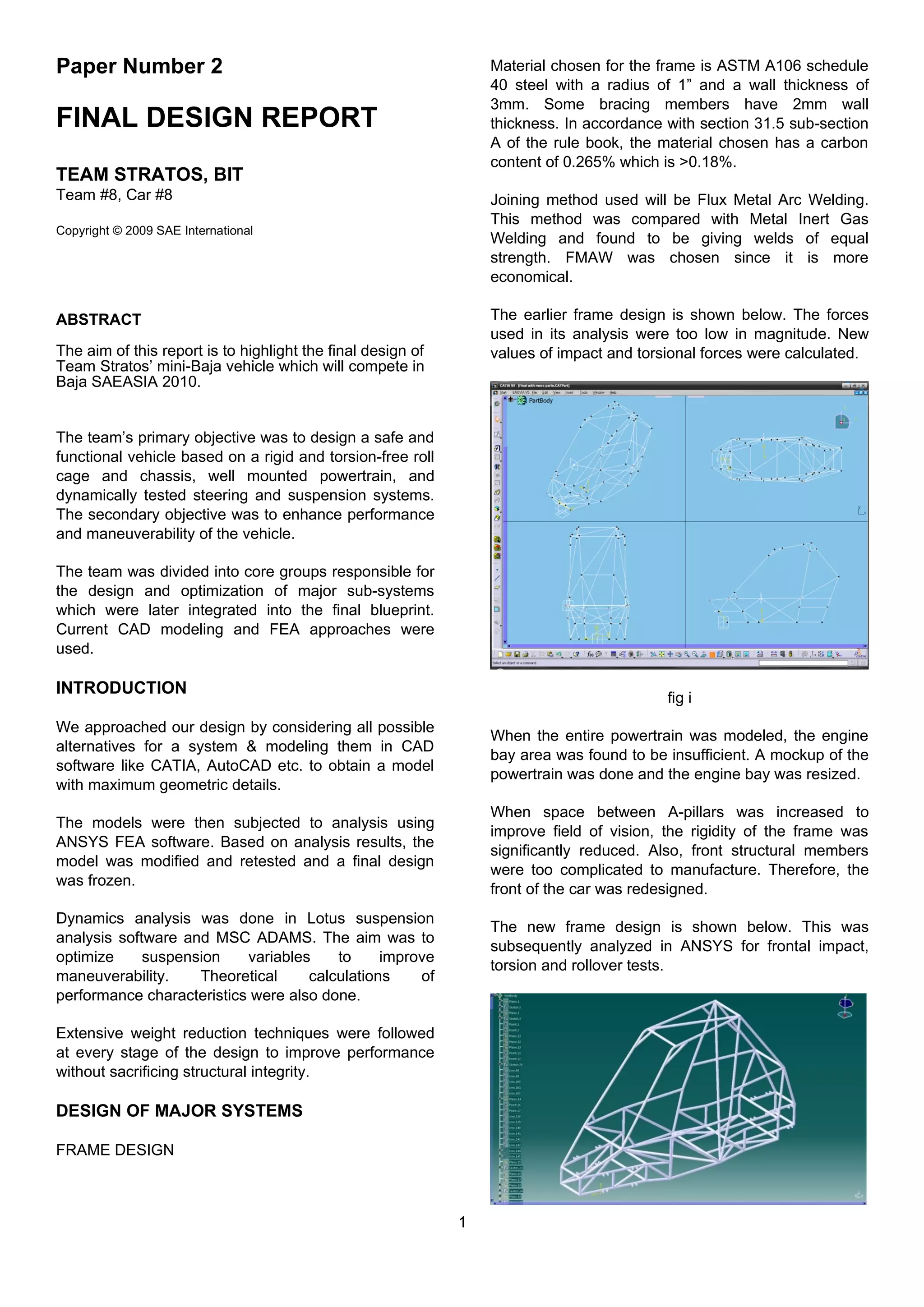
Frontal Impact Test:
For a perfectly inelastic collision, energy transferred is
DE = ½ (m1m2/m1+m2)(u2-u1)2
where m1 and m2 are
masses of two vehicles and u1 and u2 are
corresponding velocities. Assuming m1=m2=350kg
and u2=0 (vehicle at rest),
DE = 1/4 m1u1
2
& F=DE/t where t=100ms
Then, F= [.25 x 350 x (16.67)^2] / [10x.1] = 24315N
Hence, a frontal impact force of 6000N was applied at
4 points on the frame. The back of the frame was
completely constrained.
The deformation and stresses are shown below. For a
stress of 67MPa, the FOS obtained was 5.15.
fig iii (a & b)
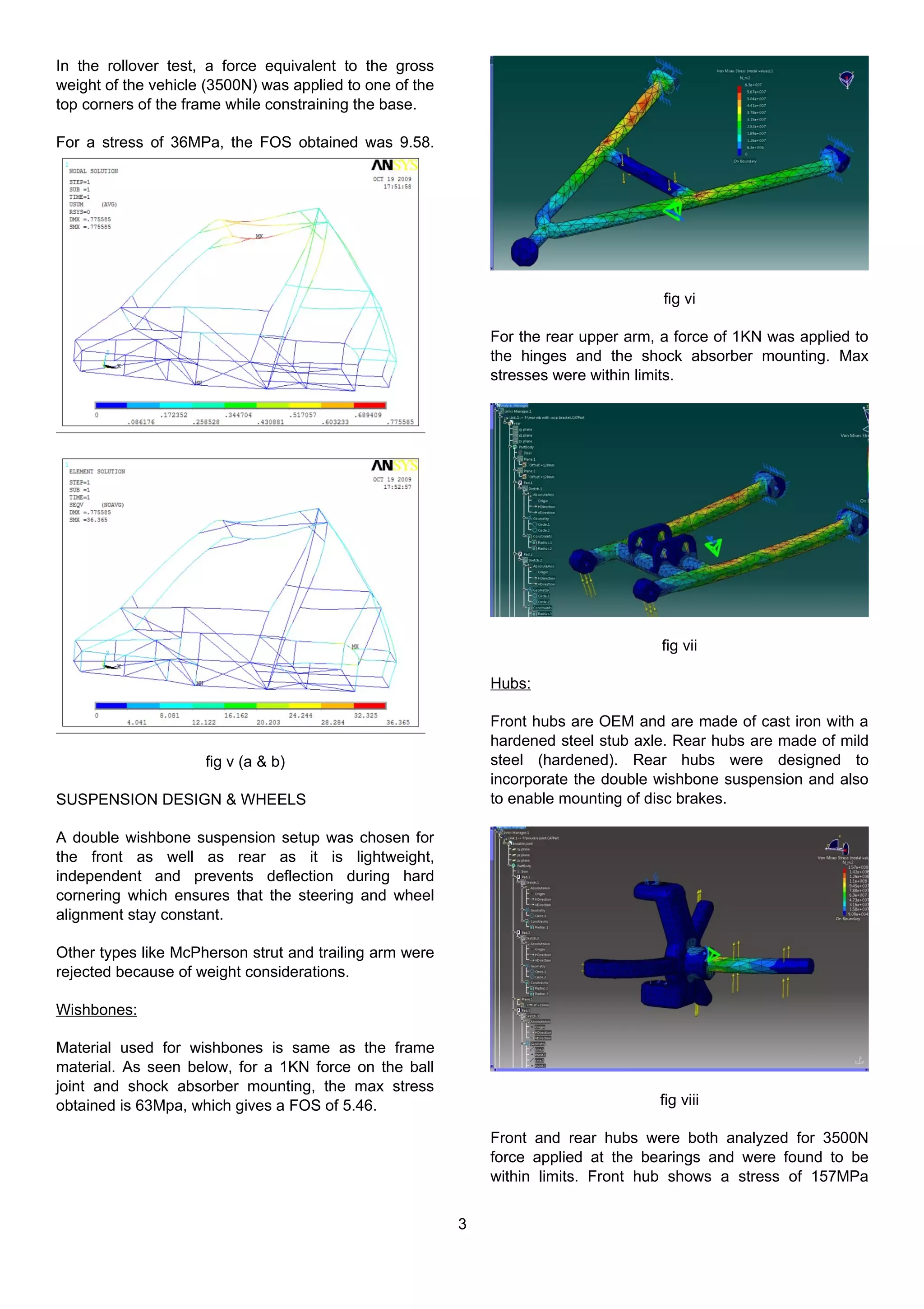
Torsion Test:
For torsion test, a force equivalent to the gross weight
of the vehicle (3500N) was applied at one of the 4
corners of the frame while constraining the other 3.
Deformation and stresses were as follows. For a stress
of 163MPa, the FOS obtained was 2.12.
fig iv (a & b)
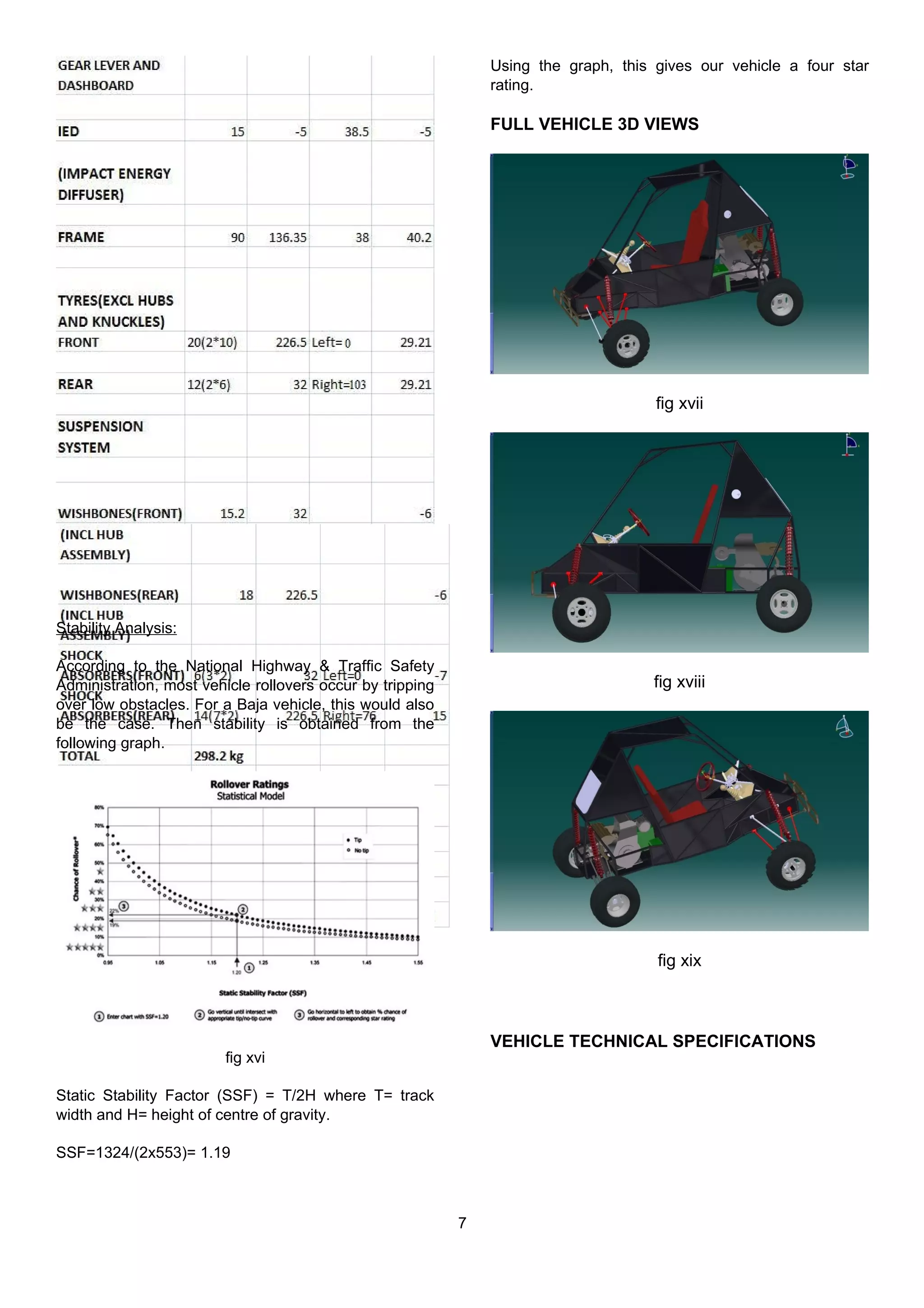
Rollover Test:
2](https://image.slidesharecdn.com/bajaproject2010reportbybangaloreinstitueoftech-130629002318-phpapp01/75/Baja-project-2010-report-by-bangalore-institue-of-tech-2-2048.jpg)
![provide different steering settings depending on the
user’s preferences. It utilizes a spring loaded locking
mechanism to hold the steering column in preset
positions. It can also be moved completely out of the
way to enhance ease of ingress/egress.
EXPECTED PERFORMANCE
CHARACTERISTICS
POWER & TORQUE:
Power to Weight ratio is (10.72/275)*1000 = 39
bhp/ton. Torque is calculated as follows.
BRAKING DISTANCE:
Using OEM master cylinders & assuming force applied
by driver on pedal to be 85lbs = 386N, force on master
cylinder = 386 x 0.26 (dist in m from pedal to cylinder)
= 100.36N
Now, this is equal to F x ram length, i.e. 100.36=Fx.08
so F=1254.5N
Then, pressure delivered by the cylinder P=F/A =
1254.5/314.15e-4 = 39,933N/m^2
Assuming front:rear brake bias as 68:32 gives
P(f)=27154.4N and P(r)=12788.6N.
Hence, force applied by the rear cylinder F(r) = P(r)*A
= 490.9e-4*12788.6 = 627.70N and similarly, F(f) =
1333.1N.
Also Force applied on the discs by the cylinder F(R) =
2*F(r)*µ = 2*627.70*0.3 = 376.62N and F(F)=798.7N.
Which implies torque on each disc in the rear= T(R)=
F(R)*Radius = 376.62*0.06 = 22.6N and that on the
front (with radius of the disc=0.08 m) T(F)=63.9N
Finally force per wheel in the rear becomes F(Rw) =
T(R)/Radius of the wheel (R(w)) = 22.6/0.292 = 77.36N
and also F(Rr) = 218.72N.
Thus, net deceleration Acc=[2*F(Rw)+2*F(Rr)]/Weight
of the vehicle(W) = 2(77.36+218.72)/3500 =
16.9m/s^2.
And, Stopping distance D(s) = V^2/2*a =
(14*14)/2*16.9 = 2.89m.
C.o.G & WEIGHT DISTRIBUTION:
C.o.G calculations were done by considering the
origin at the front end for X, at the chassis for Z and at
the wheels for Y. The final value for Z was arrived at
after adding the ground clearance.
6](https://image.slidesharecdn.com/bajaproject2010reportbybangaloreinstitueoftech-130629002318-phpapp01/75/Baja-project-2010-report-by-bangalore-institue-of-tech-6-2048.jpg)

This document provides a summary of the final design report for Team Stratos' mini-Baja vehicle that will compete in Baja SAEASIA 2010. The team divided responsibilities for major subsystems and used CAD modeling, FEA analysis, and dynamics simulations to optimize the design. Key aspects of the vehicle design include a roll cage frame made of steel that was analyzed for impact, torsion, and rollover testing. A double wishbone suspension and disc brakes were chosen. Ergonomic features like an adjustable seat and tilt steering were included for safety. Performance estimates indicate a 0-60 time of 7 seconds and a braking distance of 2.89 meters.


