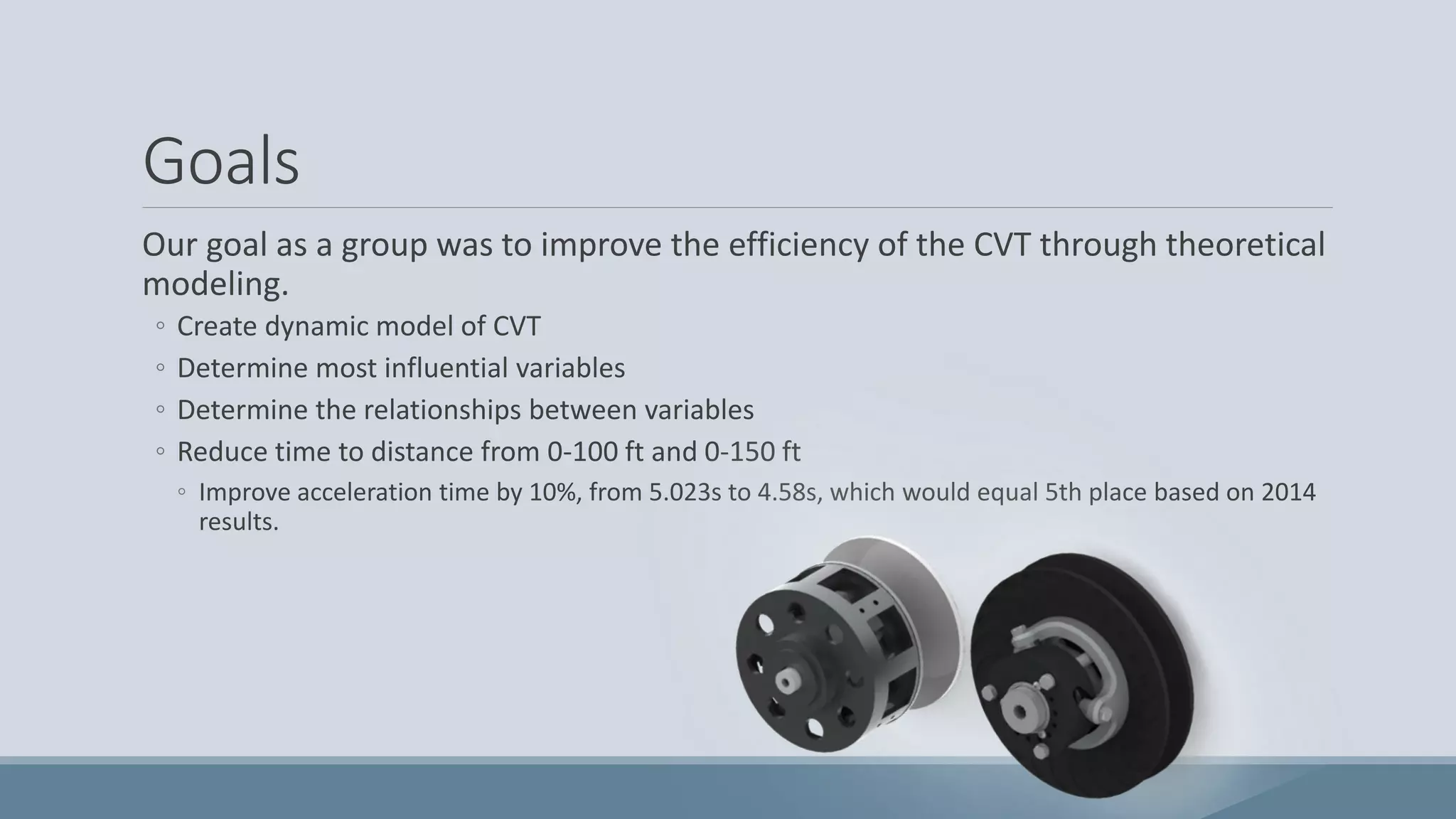
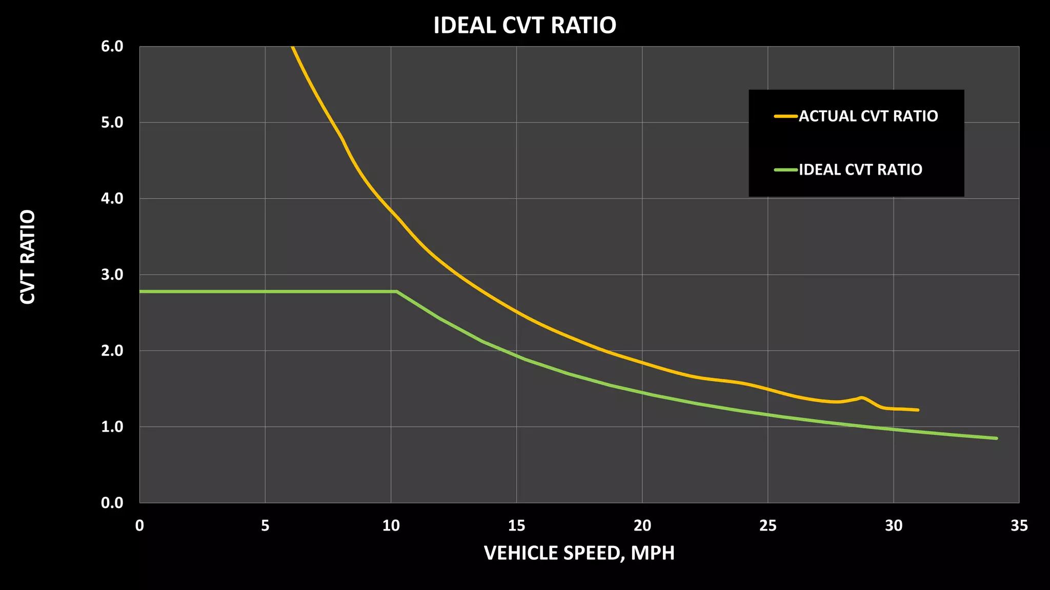
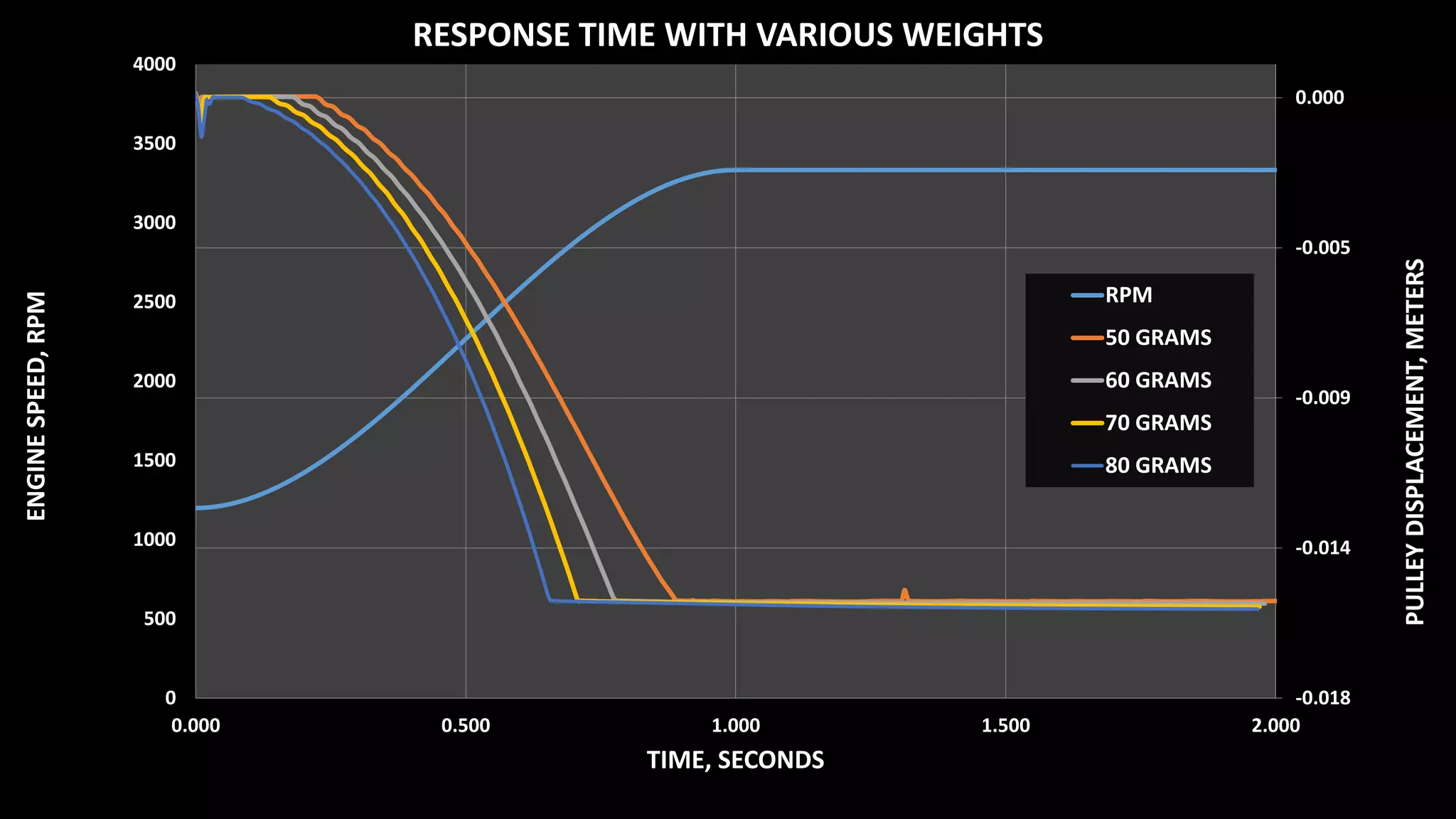
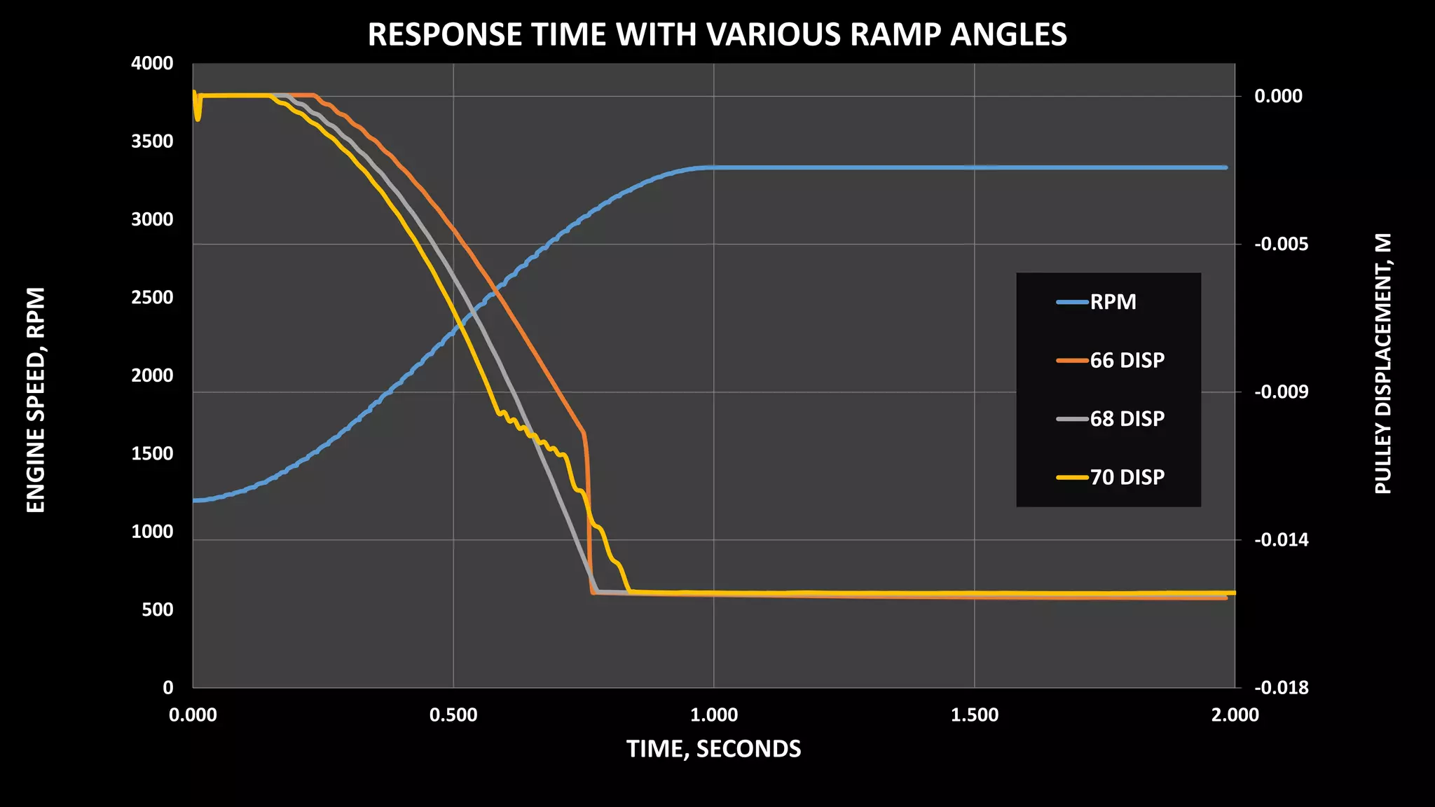
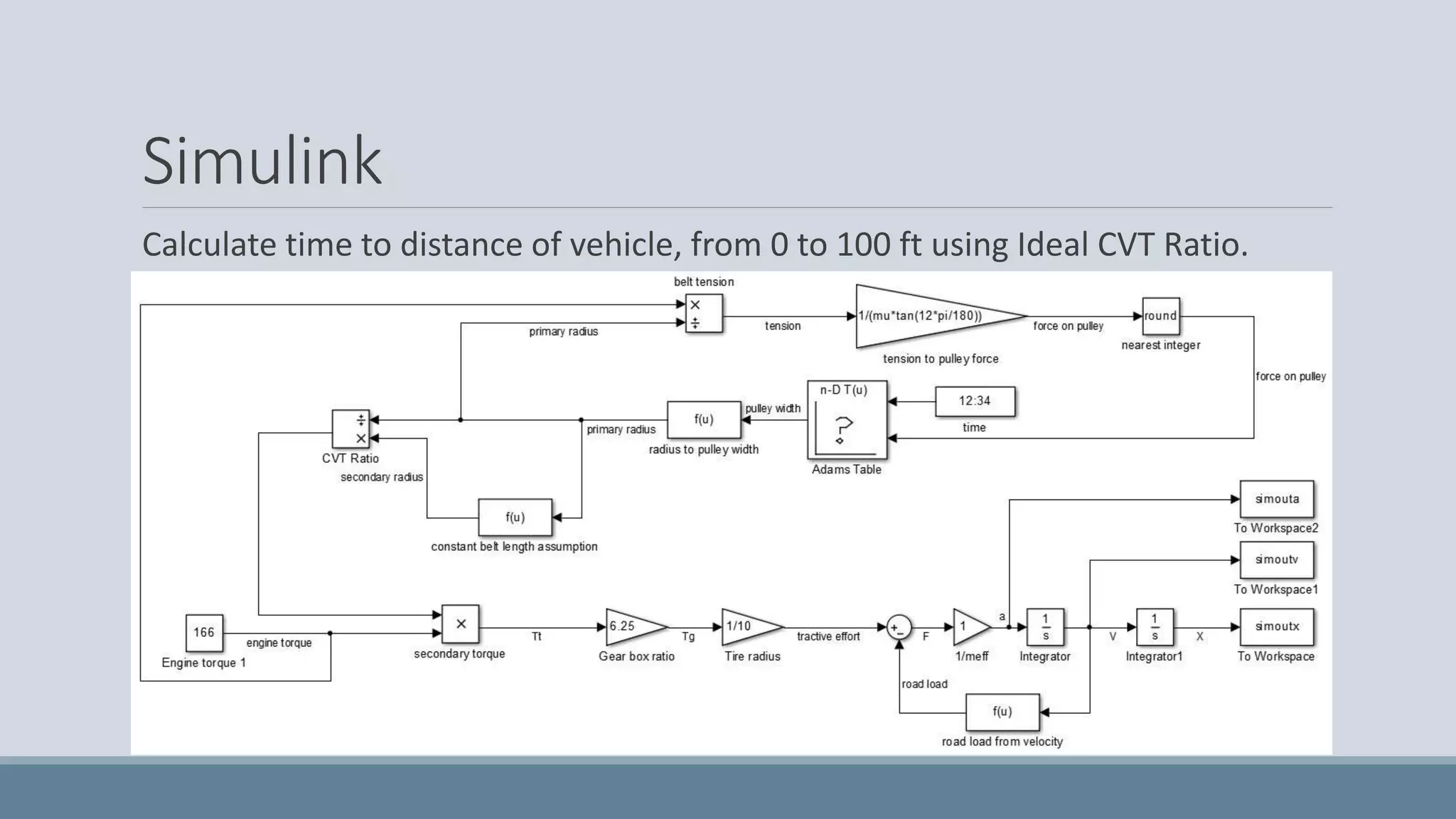
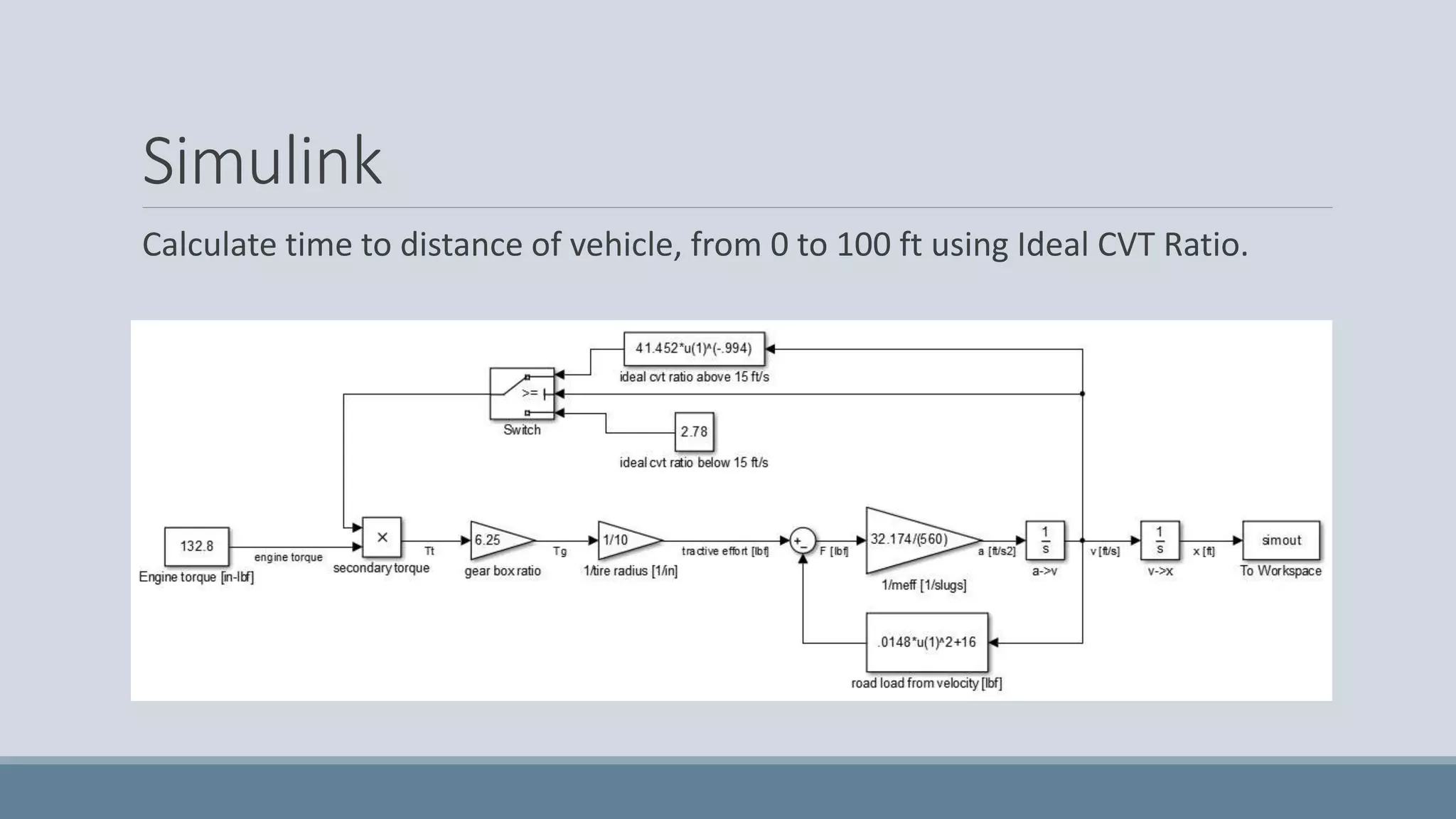
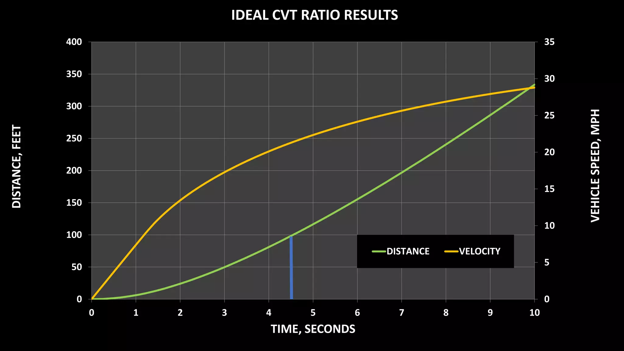
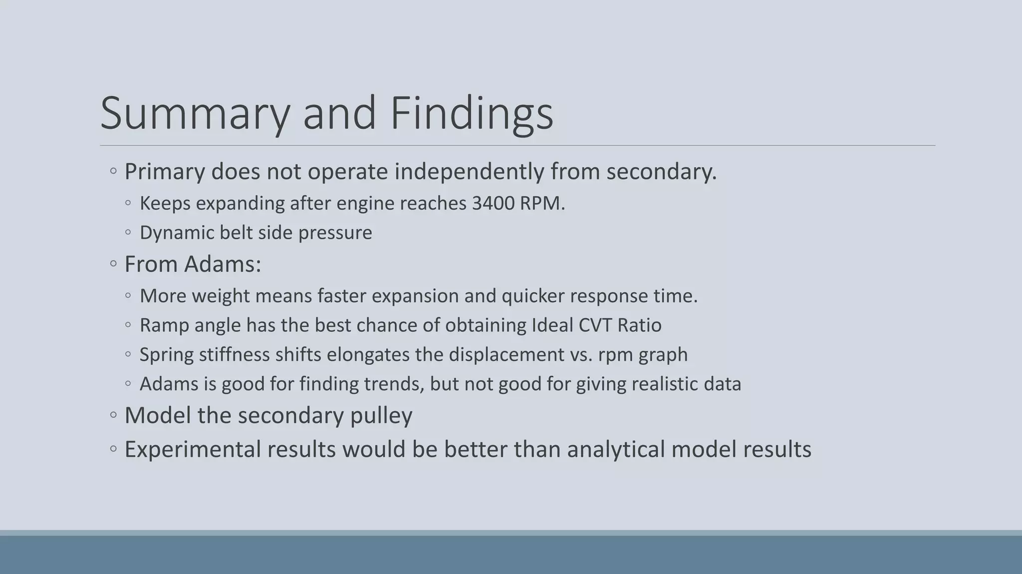
The team created theoretical models of the continuously variable transmission (CVT) on the Cal Poly Baja car to improve performance. Their Adams model showed that increasing weight on the primary pulley results in faster expansion and quicker response time. Their Simulink model calculated that using the ideal CVT ratio would reduce the 0-100 ft time to under 5 seconds, improving their acceleration time by over 10%. Testing different ramp angles on the primary pulley also showed potential for obtaining the ideal ratio. Experimental validation was recommended over relying solely on analytical models.
CVT transmission can change seamlessly through an infinite number of effective gear ratios between maximum and minimum values giving jerk free driving experience.
In this presentation we mainly discuss about Variable-diameter pulley (VDP) and how basically it functions.
CVT transmission can change seamlessly through an infinite number of effective gear ratios between maximum and minimum values giving jerk free driving experience.
In this presentation we mainly discuss about Variable-diameter pulley (VDP) and how basically it functions.
A continuously variable transmission (CVT) (also known as a single-speed transmission, stepless transmission, pulley transmission, or, in case of motorcycles, a twist-and-go) is an automatic transmission that can change seamlessly through a continuous range of effective gear ratios. This contrasts with other mechanical transmissions that offer a fixed number of gear ratios. The flexibility of a CVT allows the input shaft to maintain a constant angular velocity.
A belt-driven design offers approximately 88% efficiency, which, while lower than that of a manual transmission, can be offset by lower production cost and by enabling the engine to run at its most efficient speed for a range of output speeds. When power is more important than economy, the ratio of the CVT can be changed to allow the engine to turn at the RPM at which it produces greatest power. This is typically higher than the RPM that achieves peak efficiency. In low-mass low-torque applications a belt driven CVT also offers ease of use and mechanical simplicity.
Drivetrain was designed and manufacture in such a way that it provides good acceleration, top speed and is reliable on different terrains. To obtain an infinite range of gear ratios so as to obtain the highest torque and as well reach the maximum speed, a CVT along with a self-designed auxiliary reduction gearbox was incorporated. Also driver comfort and fuel economy were include by using CVT.
•SAE Baja is an Inter-colligate off road racing competition where the top engineering colleges in India successfully fabricate and race there all-terrain vehicles.
•The competition has various automotive giants like Mahindra, General motors etc. powering the event.
•The contest challenges each team to function as a firm whose objective is to design, fabricate, market and race off their vehicles that would be evaluated on a variety of manufacturing angles by various professionals from the sponsoring automotive companies.
Presentation made during the SAE Mini-BAJA 2009 competition. The objective was to prove the mass manufacturing capability of the ATV primarily, designed and manufactured by students.
A Continuous Variable Transmission (CVT) is a common transmission system used in low power engines as in ATV or motorcycles. This system is also used by the Baja SAE USB vehicles prototypes and motivated by the willingness to improve the performance of the prototype; I developed a final degree project which aims to describe the dynamic behavior of this system. The result was an algorithm that simulates the dynamic behavior of the vehicle given certain parameters. This project was to opt for mechanical engineering degree, earning an honorable distinction for it.
DESIGN AND FABRICATION OF SINGLE REDUCTION GEARBOX WITH INBOARD BRAKINGabdul mohammad
An inboard braking system is an automobile technology where in the disc brakes are mounted on the chassis or to the gearbox of the vehicle, rather than directly on the wheel hubs.
The main advantages are a reduction in the unsprung weight of the wheel hubs, as this no longer includes the brake discs and calipers; also, braking torque applies directly to the chassis or the gear box , rather than being taken through the suspension arms.
Inboard brakes are fitted to a driven axle of the car, as they require a drive shaft to link the wheel to the brake. Most have thus been used for rear-wheel drive cars, although four-wheel drive and some front-wheel drives have also used them.
PERFORMANCE INVESTIGATION OF A CONTROLLED DIFFERENTIAL CONTINUOUSLY VARIABLE ...ijiert bestjournal
Now a day�s development trends in car industry and mobile machines are driven by universal concerns on energy limitations and greenhouse gases reduction,more energy efficient and environmentally friendly vehicles will be needed. A s the increasing concerns in the impact of vehicle emissions of carbon dioxides and Nitrogen oxides on the biosphere combined with today�s shortage fuel,hence need to find alternate fuel solutions o r develop the transmission system in such a way tha t lower consumption and lower emission should takes p lace. Continuously variable drive is the type of automati c transmission that allows selection of infinite number of transmission ratios within the finite ran ge i.e. between minimum and maximum value. Continuously variable drive is 34.91% more efficien t than that of manual transmission. In order to achieve emission reduction and fuel economy needs t o improve fuel efficiency. Continuously variable drive can be improved by coupling differen tial gear assembly to one of variable speed drives;we can increase the speed variation range a t the expense of the horse power range. Numerous combinations of the variables are possible
Dynamic Balancing of the Vehicle while Cornering is the concept to avoid Roll-Over of the vehicle and provide comfort to the passengers while cornering by tilting the vehicle opposite to the centrifugal force to cancel it, which leads to shift of C.G point of vehicle and provide comfort to the
Passengers.
Design And Manufacturing Of Motorsports VehicleIJERA Editor
The objective of this project was to design and manufacture a racing vehicle for participation in various GOKARTING
competition. The vehicle was designed by using mathematical modeling and computer-aided design,
CAD and simulation by using a ANSIS software.The kart is introduced to the various on road compititions like
International Series of Karting orhanised by Mean Metal Motors and Trinity Series Trophy. Kart was having a
unique feature of Quick streeing mechamism. Additionally we have made the innovations like after tilting the
vehicle accidently above 60 degree tilting angle the engine automatically shuts off and engine starts only by
putting thr seat belt.It made the vehicle light weight, stable, efficient with having high strength and durability as
well. Main goal of our kart making was compact design, maximum performance as well as safety.
Design and Analysis of Pedal Box with Braking Systemijtsrd
A design process for an automotive pedal box system is presented in this paper. The work begins with a review of research carried out on pedal box system. It is followed by the process of designing a complete pedal box system. Reverse engineering process by using a steel pedal box system by use of MS Plate. The Pedal box design with proper pedal ratio and the use of single brake for both front and rear braking is designed. Md. Hameed | B. Praveen Kumar | B. Rohit | B. Surya Sai | G. Sai Kiran ""Design and Analysis of Pedal Box with Braking System"" Published in International Journal of Trend in Scientific Research and Development (ijtsrd), ISSN: 2456-6470, Volume-3 | Issue-3 , April 2019, URL: https://www.ijtsrd.com/papers/ijtsrd23413.pdf
Paper URL: https://www.ijtsrd.com/engineering/mechanical-engineering/23413/design-and-analysis-of-pedal-box-with-braking-system/md-hameed
final year project report by mechanical engineering student of career point university kota. The Soft Car design proposal has swing 90 degrees. It can pull up alongside a parking space and drive in sideways.
This presentation is on the based on case study done by using line balancing technique which a prime concern for an industrial engineer. This shows an efficient line balancing for a better production line performed at Runner Automobiles Ltd, Bangladesh.
1. CVT Project
MATT MYERS, DELANEY BALES, TAYLOR VANDENHOEK, ALEK LINQUIST,
JESS MCCAFFERTY
ME 416, FALL 2014
2. Background
CVT - Continuously Variable Transmission
◦ Transitions between an infinite number of gear ratios
◦ Primary pulley driven by engine RPM
◦ Secondary pulley driven by torque
Baja Team runs a CVT to transfer power from the engine to the gearbox.
4. Purpose
The CVT on the Cal Poly Baja car has several factors leading to inefficiencies and
improper tuning.
◦ Last year we tried tuning the CVT with different weights.
◦ Placed 33rd in the Acceleration Event with 5.023 seconds
◦ 1st place had a time of 4.199 seconds
CVT should be custom tailored for Baja Car.
This model would be used by the Baja Club to predict CVT performance based
on variable inputs.
5. Goals
Our goal as a group was to improve the efficiency of the CVT through theoretical
modeling.
◦ Create dynamic model of CVT
◦ Determine most influential variables
◦ Determine the relationships between variables
◦ Reduce time to distance from 0-100 ft and 0-150 ft
◦ Improve acceleration time by 10%, from 5.023s to 4.58s, which would equal 5th place based on 2014
results.
6. Baja Vehicle Performance
Tractive Effort Curve
◦ Ideal Tractive Effort
◦ Actual Tractive Effort
◦ Road Load
◦ Traction Limit
Ideal CVT Ratio
MOTOR CVT GEARBOX CVJ TIRES
η = 96%
η = 98%10 HP
η = 85%
3.5-0.9:1 6.25:1
Reff = 10in.
9. Theoretical Model
SolidWorks model of CVT primary pulley.
Adams simulation of primary pulley to generate the pulley diameter as a
function of time and belt tension.
Simulink model to calculate time to distance of the vehicle.
SolidWorks Adams Simulink
10. Assumptions
RPM increases steadily (no longer constant)
Asphalt, no slip
Ignore belt stretching
Constant belt length and width
Constant center-to-center distance between pulleys
Constant effective vehicle mass
14. Adams
Import SolidWorks model and run primary pulley to generate
pulley diameter as a function of time and belt side pressure
Can control:
◦ Belt Side Pressure
◦ Engine RPM
◦ Weights
◦ Spring Rate
21. Summary and Findings
◦ Primary does not operate independently from secondary.
◦ Keeps expanding after engine reaches 3400 RPM.
◦ Dynamic belt side pressure
◦ From Adams:
◦ More weight means faster expansion and quicker response time.
◦ Ramp angle has the best chance of obtaining Ideal CVT Ratio
◦ Spring stiffness shifts elongates the displacement vs. rpm graph
◦ Adams is good for finding trends, but not good for giving realistic data
◦ Model the secondary pulley
◦ Experimental results would be better than analytical model results
22. References
Aaen, Olav. Clutch Tuning Handbook. 2007. Print.
Adams Tutorial Kit for Mechanical Engineering Courses. 2nd ed. MSC Software. Print.
Budynas, Richard, and J. Keith Nisbett. Shigley's Mechanical Engineering Design. 9th ed. New York:
McGraw-Hill, 2011. Print.
Cha, S.W., W.S. Lim, and C.H. Zheng. "Performance Optimization of CVT for Two-Wheeled
Vehicles." International Journal of Automotive Technology 12.3 (2010): 461-68. Print.
Chang-song, Jiang, and Wang Cheng. Computer Modeling of CVT Ratio Control System Based on
Matlab. IEEE, 2011. 146-150. Print.
Narita, Yukihito. "Design of Shaft Drive CVT - Calculation of Transmitted Torque and Efficiency." Power
Transmission and Gearing Conference. Vol. 5B. ASME, 2005. 875-881. Print.
Willis, Christopher Ryan. A Kinematic Analysis and Design of a Continuously Variable Transmission.
Blacksburg, VA: Virginia Polytechnic Institute and State University, 2006. Print.
Editor's Notes
At the start of our project, we wanted to obtain a complete model of the CVT used in the baja car, with the goal of being able to input various geometric parameters, as well as spring constants and preloads, and output a theoretical time to speed. This time to speed could then be used to either adjust the parameters, or compare to experimental data in order to calculate efficiencies of various parts of the system.
Research shows that the CVT mainly operates as follows:
Power is transferred from the engine to the primary pulley, which starts at a high width, small belt radius. As speed increases, flyweights in the stationary section of the primary are thrown outward, causing a normal force against the ramps mounted on the moving section of the primary. Both sections are constrained to rotate with the same angular velocity, but can move axially. Axial movement is impeded by a linear spring in between the two sections. Force created by the rotation of the flyweights is opposed by the linear spring, both of which determine how quickly the pulley will contract. As speed increases, the primary pulley width decreases, pushing the belt to higher radii.
As the belt is pushed to higher radii by the primary, the radius of the secondary is pulled inward, due to the tension of the belt. This decrease in radius is impeded by a torsional spring in the secondary, which acts through rollers against a helix on the stationary part of the secondary. The main effect of the spring in the secondary is to impeded the axial acceleration of the secondary, which causes a smaller change in gearing.
Overall, the CVT operates from around a 4:1 ratio at low speeds to a .75:1 ratio at high speeds. Continuous changing of the gearing allows for maximum tractive force to be applied at all times, as well as allowing the engine to operate at a constant RPM during acceleration. The tradeoff for this is efficiency, as belt slippage results in a lower overall efficiency.
Goals Recap
We did create a dynamic model.
Not every variable was considered so it was difficult to find the most influential, however the ramp angles (seen later in PPoint) of the CVT has the most promise for improvement of CVT Ratio
Weights are important
Belt tension has a huge effect on how the primary responds, but we weren’t sure how to obtain it or model it.
Relationships were hard to determine, but trends were visible. Power curve fit did model ideal CVT ratio well.
Time to distance was reduced with Ideal CVT Ratio
After many difficulties to obtaining a theoretical model, our focus and goals turned more to finding out how the Primary CVT works and we thought we could make the Secondary a dependent of the Primary, which is untrue and possibly the opposite.
These are the Baja vehicle parameters that we used for all our calculations that were used in the Excel file.
TRACTIVE EFFORT Figure: This figure shows the ideal tractive effort capable with the Baja car and the actual tractive effort using the efficiency values given in the previous slide. The traction limit is also shown and this value was calculated in the accompanying Excel file. As you can see we are traction limited up until about 10 MPH, this has a huge impact on the ideal CVT ratio as you will see in the next slide. Also, no slip was an important assumption in gaining the tractive effort value. The road load is also calculated and that curve is also calculated in the Excel File.
IDEAL CVT RATIO Figure: This plot shows the ideal CVT ratio that we calculated from the data in the Tractive Effort Figure. The CVT Ratio accounts for the tractive effort and sets it around 2.8 so the tires do not slip. After we are no longer traction limited, the ideal ratio begins to decline. The rate at which it declines is determined by the Actual Tractive Effort which we calculated. A sample of the actual CVT ratio was collected from an experimental test run of the Baja vehicle on asphalt. From visual inspection, the tires are slipping below about 12 MPH and overall the CVT ratio is always higher than ideal thus not allowing for maximum acceleration. It should be noted that from experience that either the traction limit is too low or the actual tractive effort is too high as the Baja car does not spin out up to 10 or 12 MPH; there must be some discrepancy, however the general Ideal CVT Ratio curve is valid.
This was the game plan we had for starting the project.
Assumptions:
At first, we used an constant RPM but this gave us no results in Adams as we didn’t have the secondary model to talk to the primary. We had to use a step function for RPM so we could get actual trends.
Asphalt assumption made it simpler to analyze.
No belt stretching and constant length and width helped simplify it and wasn’t important for what we were trying to achieve.
Didn’t want to get involved with changing center to center distance.
Constant effective vehicle mass allowed us to simplify our model even further. Effective mass calculation was performed by the Baja team last year.
Ramps were modeled as linear, with a single break point in the middle. This however, is not a fully accurate representation of the ramps. In reality, the break point divides two non-linear portions of the ramp. As we did not fully understand the functions which determined the ramp angle, a linear model was created to find the relationships between ramp angle and tractive effort.
The most important takeaway here is the weight-link angle, which will be defined as the angle between the radial axis of revolution and the line drawn between the weight and the pin connecting the link to the main body. Here it is shown at ~90°.
MODELED WITH CONSTANT BELT SIDE PRESSURE
This model incorporated an overly stiff opposing spring force between the pulley faces to simulate the belt, in order to delay pulley expansion. As mass goes up, more force is generated due to centripetal acceleration, causing a quicker pulley expansion.
Changing the mass also changes the pulley displacement at a given RPM, with more mass causing more pulley displacement for a given RPM.
This concurs with research on clutch tuning, which indicated that the primary weight and spring system mainly effect on the engagement speed of the engine.
MODELED WITH CONSTANT BELT SIDE PRESSURE
Changing the ramp angle involved a larger amount of complexity in modeling, as it was a geometry consideration only. Research on clutch tuning indicates that the changing ramp angle should be a last resort, as is makes tuning the primary much more difficult.
Ramp angle was tested in ADAMS at three different configurations:
The 66° ramp had a 68° angle to begin, and a 66° angle after the break point.
The 68° ramp had no break point, and continued at a 68° angle.
The 70° ramp had a 68° angle before the break point, and continued after at 70°.
The graphs shown here give a relationship between ramp angle steepness and pulley displacement. Due to the nature of the geometry construction of the ramps in solid works, changing the post-breakpoint angle also changed the geometry of the pre-breakpoint ramp, resulting in a small change in the engagement times and slopes the displacement curve. Since the actual time to displacement was not being calculated, this can be disregarded. It does, however, give us insight into what changing the initial weight-link angle affects in terms of pulley response. For the 66° ramp, initial distance was higher, causing a lower weigh-link angle, which caused less effective side force on the pulley, delaying expansion. With a higher weight-link angle, a larger component of the centripetal acceleration is in the direction of expansion, leading to a quicker response time.
The main purpose of these tests, however, was to understand the relationship of the post-breakpoint angle to expansion. As can be seen, higher ramp angles cause a slower expansion with respect to engine speed.
Out of these graphs, the main takeaway is that the ramp geometry primarily determines the weight-link-to-ramp contact angle, which is the most important variable in determining pulley expansion. This variable determines how force will be distributed(radially or axially). Since only axial force contributes to the expansion of the primary, the greater this angle, the more quickly expansion will occur. Unfortunately, this angle is extremely difficult to calculate dynamically, leading to our reliance on ADAMS.
Ideal SIMULINK LOOP
The Simulink model is a basic dynamic model working from a constant engine output torque. The torque is altered through the CVT and drive train components in order to supply the tractive effort at the ground. This tractive effort, minus the road load, accelerates the car. The acceleration is then integrated twice, resulting in the car position as a function of time. During acceleration, the CVT ratio will ideally be changing. The model simulates this change in ratio by using relationships obtained from the Adams model simulation. For the primary pulley, the effective diameter is a function of the belt tension, and the rotational speed. For the secondary, the effective diameter is a function of the belt tension and the transmitted torque. Since we did not get relationships for the secondary pulley, we assumed that the secondary diameter is a function of the primary pulley diameter and the belt length. This assumption would be helpful, but since a second assumption was that the transmitted torque was constant, the primary pulley effective diameter remained constant and in turn the ratio remained constant.
This SIMULINK program uses the ideal CVT ratio, calculated to exactly produce the maximum possible tractive effort at each time.
Inputs are Engine Speed and Ideal CVT ratio. Outputs a time to distance graph. In order to check the Simulink model and ensure that the concept of making the ideal CVT ratio happen would improve our time to distance, we replaced the varying CVT ratio with a calculated ideal ratio function. Using this function for the ratio gave results of a 4.5 second time to reach 100 ft. This time is over 10% better than the results of the current baja car.
Ideal Time to Speed and Distance Graph from SIMULINK Model
This gives a baseline to measure efficiency off, showing a theoretical ~4.5 Seconds to 100 Ft.
Without the secondary spring, the secondary would essentially be a slave to the primary.
With a torsional spring, the side force operating on the belt due to the primary is opposed by the secondary, causing fluctuations in belt tension, as well as a time delay in acceleration, and thus expansion, of the pulley.
General relationships can be drawn from ADAMS, and used to experimentally tune the clutch.
The next step would be to model the secondary pulley in ADAMS, and find a way to connect the two.
The best results would come experimentally.