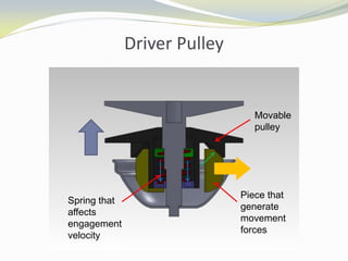
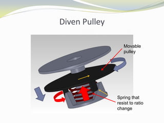
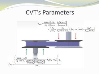
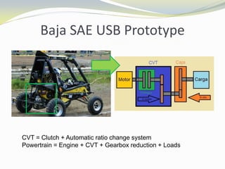
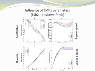
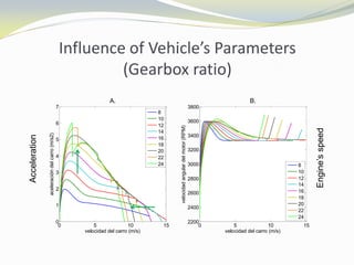
Done by:
Reinaldo Alexander Wiener Rocca
Academic tutor: Prof. Sergio Díaz
General objective
 Create a numerical simulation that allows to change
the most important parameters of the CVT, to study
the influence of each one, in the dynamic
performance, under different track conditions.
Specific Objectives
 Disassembly a CVT CVTech IBCTM brand Model #
0600-0021 / 5600-0171 to understand the internal
physical reactions and to obtain the equation of
motion of the system.
 Obtain a model of vehicle’s motion that simulates the
process of clutching and ratio change during
movement, contemplating various track conditions.
 Validate the model by comparing with experimental
measurements on the prototype USB Baja SAE 2010.
Specific Objectives
 To study the influence of CVT ‘s parameters, the final
drive ratio and other important parameters; in
different output variables such as engine speed, vehicle
speed, acceleration, distance traveled, among others.
 Establish a methodology for selection of transmission
ratio(s) of the final gear reduction of the prototype.
 Establish a methodology for selecting optimal
parameters in the CVT, to improve prototype’s
performance.
Belt-CVT
 Transmit power from the
driving shaft to driven
shaft offering different gear
ratio values and
maintaining engine speed
constant.
 Ratio changes are
sequential and infinite
within a range and are
made automatically.
 Each pulley has a movable
semi-pulley to enable ratio
changes.
Mini-Baja prototype’s CVT behaviour
Vehicle’s Dynamics model
Driver Pulley
Movable
pulley
Piece that
generate
movement
forces
Spring that
affects
engagement
velocity
Diven Pulley
Movable
pulley
Spring that
resist to ratio
change
CVT’s Parameters
Baja SAE USB Prototype
CVT = Clutch + Automatic ratio change system
Powertrain = Engine + CVT + Gearbox reduction + Loads
Experimental Validation of the model
Model results
Experimental test (Left) vs.
Simulated results (Right)
0 2 4 6 8
2000
2200
2400
2600
2800
3000
3200
3400
3600
3800
4000
A.
tiempo (s)
Velocidaddelmotor(RPM)
C1
C2
C3
C4
0 2 4 6 8
2000
2200
2400
2600
2800
3000
3200
3400
3600
3800
4000
B.
tiempo (s)
Velocidaddelmotor(RPM)
C1
C2
C3
C4
0 2 4 6 8
0
5
10
15
20
25
30
35
40
A.
tiempo (s)
Velocidaddelcarro(km/h)
C1
C2
C3
C4
0 2 4 6 8
0
5
10
15
20
25
30
35
40
B.
tiempo (s)
Velocidaddelcarro(km/h)
C1
C2
C3
C4
Influence of CVT’s parameters
(Fsh1 – inductive force on driver pulley)
0 2 4 6 8 10 12
0
1
2
3
4
5
6
7
A.
velocidad del carro (m/s)
aceleracióndelcarro(m/s2)
150
190
230
270
310
350
390
430
0 2 4 6 8 10 12
1500
2000
2500
3000
3500
4000
B.
velocidad del carro (m/s)
velocidadangulardelmotor(RPM)
150
190
230
270
310
350
390
430
0 2 4 6 8 10 12 14
0
50
100
150
A.
tiempo (s)
distanciarecorrida(m)
150
190
230
270
310
350
390
430
0 5 10 15
0
2
4
6
8
10
12
B.
tiempo (s)
velocidaddelcarro(m/s)
150
190
230
270
310
350
390
430
AccelerationDistance
Engine’sspeedVehicle’sspeed
Influence of CVT’s parameters
(Fsh1 – inductive force on driver pulley)
 Inductive force directly affects the engine speed
 Inductive force increases the transmitted force
(acceleration).
 For higher centrifugal-weight a lower engagement
speed will be obtained, hence stiffer spring must be
used to maintain this parameter within the desired
range.
Influence of CVT’s parameters
(Fsh2 – resistive force)
0 2 4 6 8 10 12
0
0.5
1
1.5
2
2.5
3
3.5
4
4.5
5
A.
velocidad del carro (m/s)
aceleracióndelcarro(m/s2)
90
120
150
180
210
240
270
0 2 4 6 8 10 12
2200
2400
2600
2800
3000
3200
3400
3600
3800
B.
velocidad del carro (m/s)
velocidadangulardelmotor(RPM)
90
120
150
180
210
240
270
0 2 4 6 8 10
0
10
20
30
40
50
60
70
80
90
100
A.
tiempo (s)
distanciarecorrida(m)
90
120
150
180
210
240
270
0 2 4 6 8 10
0
2
4
6
8
10
12
B.
tiempo (s)
velocidaddelcarro(m/s)
90
120
150
180
210
240
270
AccelerationDistance
Engine’sspeedVehicle’sspeed
Influence of CVT’s parameters
(Fsh2 – resistive force on driven pulley)
 Influences directly in the clutching/engagement time.
 Have influence on the top speed.
 Generates different effects comparing to inductive
forces.
Influence of Vehicle’s Parameters
(Gearbox ratio)
0 5 10 15
0
1
2
3
4
5
6
7
A.
velocidad del carro (m/s)
aceleracióndelcarro(m/s2)
8
10
12
14
16
18
20
22
24
0 5 10 15
2200
2400
2600
2800
3000
3200
3400
3600
3800
B.
velocidad del carro (m/s)
velocidadangulardelmotor(RPM)
8
10
12
14
16
18
20
22
24
Acceleration
Engine’sspeed
Gearbox ratio computation (design parameter)
Methodology to optimize CVT’s performance
Gearbox ratio computation
Knowing the top speed
vc (m/s) d (m)
9 20
10 25
11 30
12 45
13 70
14 120
15 160
Load
curve
Gearbox ratio selection
 The optimal value is one that delivers maximum
acceleration without sacrificing the top speed of the
vehicle or the value which delivers maximum energy
in a fixed distance.
 Once top speed is obtained, kinematical relationship
is used to estimated the necessary gearbox ratio.
Optimization of CVT’s performance
 Maximizing the tension
during clutching (taking
advantage of the slip
energy).
 Keep engine operating
within the range of
maximum power.
 Keep CVT uncoupled at
engine’s idle speed.
 Upper limits (Efficiency
and structural damage) are
not covered in this work.
0,00
1,00
2,00
3,00
4,00
5,00
6,00
7,00
8,00
9,00
1500,00 2000,00 2500,00 3000,00 3500,00 4000,00
Potencia(HP)
Velocidad del motor (RPM)
Engine Power
 Step 1: Find the optimal engine speed (engine curve)
 Paso 2: Adjust parameters to obtain a high inductive force,
being careful to remain engine uncoupled at idle speed.
 Paso 3: Adjust parameters on driven pulley to balance
inductive force and to achieve desired engine speed.
0 5 10 15
0
1
2
3
4
5
6
7
A.
velocidad del carro (m/s)
aceleracióndelcarro(m/s2)
P1
P3
P5
P7
0 5 10 15
1500
2000
2500
3000
3500
4000
X: 11.6
Y: 3281
B.
velocidad del carro (m/s)
velocidadangulardelmotor(RPM)
P1
P3
P5
P7
Optimization of CVT’s performance
Conclusions
 The model fulfills the objectives satisfactorily.
 It was observed that the slip during clutching is common
and also beneficial in applications with low power engines.
This is because that kinematical energy from engine is
higher that engine’s power (10 HP) at uncoupled stage.
 Estimated values of the internal forces are obtained. This
values is useful to design the inlet shaft of the gearbox.
 It was possible to establish a methodology to select the
final drive ratio and the optimal parameters of the CVT.
Recommendations
 Find a way to measure also change of position of semi-
pulleys on driver and driven pulley, to know exactly
when change of ratio start and stop.
 Include in the model the variation of efficiency in
terms of the belt tension.
 Develop a model that describes accurately the creep
that occurs in the belt-pulley contact during ratio
change.
 Perform a test bench were inlet torque and load torque
can be controlled and measured to reduce errors.

University Final Project

  • 1.
    Done by: Reinaldo AlexanderWiener Rocca Academic tutor: Prof. Sergio Díaz
  • 2.
    General objective  Createa numerical simulation that allows to change the most important parameters of the CVT, to study the influence of each one, in the dynamic performance, under different track conditions.
  • 3.
    Specific Objectives  Disassemblya CVT CVTech IBCTM brand Model # 0600-0021 / 5600-0171 to understand the internal physical reactions and to obtain the equation of motion of the system.  Obtain a model of vehicle’s motion that simulates the process of clutching and ratio change during movement, contemplating various track conditions.  Validate the model by comparing with experimental measurements on the prototype USB Baja SAE 2010.
  • 4.
    Specific Objectives  Tostudy the influence of CVT ‘s parameters, the final drive ratio and other important parameters; in different output variables such as engine speed, vehicle speed, acceleration, distance traveled, among others.  Establish a methodology for selection of transmission ratio(s) of the final gear reduction of the prototype.  Establish a methodology for selecting optimal parameters in the CVT, to improve prototype’s performance.
  • 6.
    Belt-CVT  Transmit powerfrom the driving shaft to driven shaft offering different gear ratio values and maintaining engine speed constant.  Ratio changes are sequential and infinite within a range and are made automatically.  Each pulley has a movable semi-pulley to enable ratio changes.
  • 7.
    Mini-Baja prototype’s CVTbehaviour Vehicle’s Dynamics model
  • 8.
  • 9.
  • 10.
  • 11.
    Baja SAE USBPrototype CVT = Clutch + Automatic ratio change system Powertrain = Engine + CVT + Gearbox reduction + Loads
  • 12.
    Experimental Validation ofthe model Model results
  • 13.
    Experimental test (Left)vs. Simulated results (Right) 0 2 4 6 8 2000 2200 2400 2600 2800 3000 3200 3400 3600 3800 4000 A. tiempo (s) Velocidaddelmotor(RPM) C1 C2 C3 C4 0 2 4 6 8 2000 2200 2400 2600 2800 3000 3200 3400 3600 3800 4000 B. tiempo (s) Velocidaddelmotor(RPM) C1 C2 C3 C4 0 2 4 6 8 0 5 10 15 20 25 30 35 40 A. tiempo (s) Velocidaddelcarro(km/h) C1 C2 C3 C4 0 2 4 6 8 0 5 10 15 20 25 30 35 40 B. tiempo (s) Velocidaddelcarro(km/h) C1 C2 C3 C4
  • 14.
    Influence of CVT’sparameters (Fsh1 – inductive force on driver pulley) 0 2 4 6 8 10 12 0 1 2 3 4 5 6 7 A. velocidad del carro (m/s) aceleracióndelcarro(m/s2) 150 190 230 270 310 350 390 430 0 2 4 6 8 10 12 1500 2000 2500 3000 3500 4000 B. velocidad del carro (m/s) velocidadangulardelmotor(RPM) 150 190 230 270 310 350 390 430 0 2 4 6 8 10 12 14 0 50 100 150 A. tiempo (s) distanciarecorrida(m) 150 190 230 270 310 350 390 430 0 5 10 15 0 2 4 6 8 10 12 B. tiempo (s) velocidaddelcarro(m/s) 150 190 230 270 310 350 390 430 AccelerationDistance Engine’sspeedVehicle’sspeed
  • 15.
    Influence of CVT’sparameters (Fsh1 – inductive force on driver pulley)  Inductive force directly affects the engine speed  Inductive force increases the transmitted force (acceleration).  For higher centrifugal-weight a lower engagement speed will be obtained, hence stiffer spring must be used to maintain this parameter within the desired range.
  • 16.
    Influence of CVT’sparameters (Fsh2 – resistive force) 0 2 4 6 8 10 12 0 0.5 1 1.5 2 2.5 3 3.5 4 4.5 5 A. velocidad del carro (m/s) aceleracióndelcarro(m/s2) 90 120 150 180 210 240 270 0 2 4 6 8 10 12 2200 2400 2600 2800 3000 3200 3400 3600 3800 B. velocidad del carro (m/s) velocidadangulardelmotor(RPM) 90 120 150 180 210 240 270 0 2 4 6 8 10 0 10 20 30 40 50 60 70 80 90 100 A. tiempo (s) distanciarecorrida(m) 90 120 150 180 210 240 270 0 2 4 6 8 10 0 2 4 6 8 10 12 B. tiempo (s) velocidaddelcarro(m/s) 90 120 150 180 210 240 270 AccelerationDistance Engine’sspeedVehicle’sspeed
  • 17.
    Influence of CVT’sparameters (Fsh2 – resistive force on driven pulley)  Influences directly in the clutching/engagement time.  Have influence on the top speed.  Generates different effects comparing to inductive forces.
  • 18.
    Influence of Vehicle’sParameters (Gearbox ratio) 0 5 10 15 0 1 2 3 4 5 6 7 A. velocidad del carro (m/s) aceleracióndelcarro(m/s2) 8 10 12 14 16 18 20 22 24 0 5 10 15 2200 2400 2600 2800 3000 3200 3400 3600 3800 B. velocidad del carro (m/s) velocidadangulardelmotor(RPM) 8 10 12 14 16 18 20 22 24 Acceleration Engine’sspeed
  • 19.
    Gearbox ratio computation(design parameter) Methodology to optimize CVT’s performance
  • 20.
    Gearbox ratio computation Knowingthe top speed vc (m/s) d (m) 9 20 10 25 11 30 12 45 13 70 14 120 15 160 Load curve
  • 21.
    Gearbox ratio selection The optimal value is one that delivers maximum acceleration without sacrificing the top speed of the vehicle or the value which delivers maximum energy in a fixed distance.  Once top speed is obtained, kinematical relationship is used to estimated the necessary gearbox ratio.
  • 22.
    Optimization of CVT’sperformance  Maximizing the tension during clutching (taking advantage of the slip energy).  Keep engine operating within the range of maximum power.  Keep CVT uncoupled at engine’s idle speed.  Upper limits (Efficiency and structural damage) are not covered in this work. 0,00 1,00 2,00 3,00 4,00 5,00 6,00 7,00 8,00 9,00 1500,00 2000,00 2500,00 3000,00 3500,00 4000,00 Potencia(HP) Velocidad del motor (RPM) Engine Power
  • 23.
     Step 1:Find the optimal engine speed (engine curve)  Paso 2: Adjust parameters to obtain a high inductive force, being careful to remain engine uncoupled at idle speed.  Paso 3: Adjust parameters on driven pulley to balance inductive force and to achieve desired engine speed. 0 5 10 15 0 1 2 3 4 5 6 7 A. velocidad del carro (m/s) aceleracióndelcarro(m/s2) P1 P3 P5 P7 0 5 10 15 1500 2000 2500 3000 3500 4000 X: 11.6 Y: 3281 B. velocidad del carro (m/s) velocidadangulardelmotor(RPM) P1 P3 P5 P7 Optimization of CVT’s performance
  • 24.
    Conclusions  The modelfulfills the objectives satisfactorily.  It was observed that the slip during clutching is common and also beneficial in applications with low power engines. This is because that kinematical energy from engine is higher that engine’s power (10 HP) at uncoupled stage.  Estimated values of the internal forces are obtained. This values is useful to design the inlet shaft of the gearbox.  It was possible to establish a methodology to select the final drive ratio and the optimal parameters of the CVT.
  • 25.
    Recommendations  Find away to measure also change of position of semi- pulleys on driver and driven pulley, to know exactly when change of ratio start and stop.  Include in the model the variation of efficiency in terms of the belt tension.  Develop a model that describes accurately the creep that occurs in the belt-pulley contact during ratio change.  Perform a test bench were inlet torque and load torque can be controlled and measured to reduce errors.