Downloaded 185 times
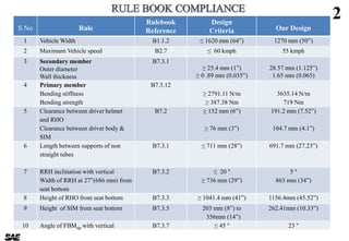
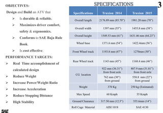
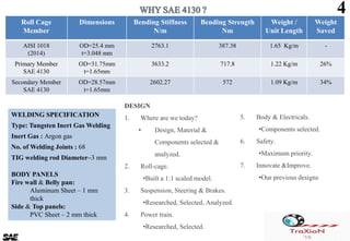

The document provides detailed design specifications and performance targets for an ATV developed by Sri Venkateswara College of Engineering, aimed at durability, driver comfort, and compliance with SAE Baja rules. Key features include design parameters such as vehicle dimensions, material choices, and component analysis, as well as performance metrics like speed, weight, and safety measures. Additionally, it outlines improvements based on lessons learned from previous designs and strategies for cost management.


