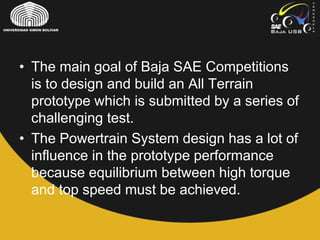
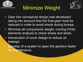
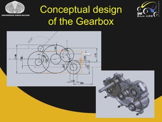
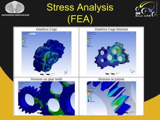
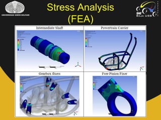
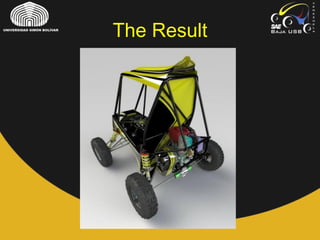
Management of
Transmission/Powertrain
Division
Baja SAE USB 2010-2011
By: Reinaldo Wiener (head of
division)
• The main goal of Baja SAE Competitions
is to design and build an All Terrain
prototype which is submitted by a series of
challenging test.
• The Powertrain System design has a lot of
influence in the prototype performance
because equilibrium between high torque
and top speed must be achieved.
• The first task as head of the division was
to recollect the information about common
problems in past competition:
– CVT overheating
– Time loss during assembly and disassembly
– Failure of transmission shaft
– Impacts at the bottom of the gearbox during
bumps
– Oil leakage in the gearbox
• After recovering the most influencing problems,
as team, we set the objectives for
powertrain/transmission team the general
objectives were:
– Improve the prototype’s dynamical response (improve
position in acceleration, and hill climb)
– Reduce car weight without sacrificing reliability
(strength-weight ratio)
– Improve the shaft resistance
– Prevent parts overheating
– Prevent oil leak
– Make all possible with a very low budget
• Characterize the CVT behavior:
– A Continuous Variable Transmission is a type of
transmission that acts like an automatic gearbox.
There are some parameters than can be modified in
order to obtain a better performance.
– Measure velocity, acceleration and time in a distance
of 150ft using telemetry equipment, using different
configurations of the CVT in previous prototypes
– Data clean up and interpretation
Dynamic Response
Vehicle Dynamics
• Characterize the aerodynamics load
curve:
– This was the first time that the load curve was
measure. The trial consist in pulling the car with a
load cell attached and measure the load and velocity
(no wind tunnel available).
• Characterize the engine curve:
– A low cost prototype with an air cooled disk brake
was design and build (dyno). It was also the first time
that the actual engine curve was obtained.
– Measure of engine torque and engine speed using a
competition engine.
Dynamic Response
RESUMEN TRANSMISION 2009-2010
Load Curve (Aerodynamics)
RESUMEN TRANSMISION 2009-2010
Dyno Tests
• Simulation of dynamic response using the
data recovered
– It is assumed that load curve from previous
prototypes are very similar to the new one
– Select the final gear reduction which is a key
parameter for the gearbox design
Dynamic Response
RESUMEN TRANSMISION 2009-2010
Estimated Curves
• Gear box conceptual design was developed
taking into account that the final gear must be
reduced in order to avoid shock during bumps.
• Minimize all components weight, running Finite
elements analysis to check stress and strain.
• Introduction of cover design to reduce oil
leakage
• Develop of a system to open the gearbox faster
for maintenance.
Minimize Weight
Conceptual design
of the Gearbox
Stress Analysis
(FEA)
Stress Analysis
(FEA)
• The output shaft connect the gearbox to the wheels. In
order to avoid output shat failure, a series of test were
performed on a shaft used by commercial ATVs.
– The first test recollected the superficial hardness of the shaft
– The second recollected the hardness in the transversal section
for different radii. This second test suggested that a thermal
treatment were performed on the shaft (probably a quenching
treatment)
– The final test were performed to study the chemical composition
of the shaft in order to study if it was a special alloy material or a
common steel. It was discovered that the material was an AISI
1040.
• This study suggest that after machining, the piece must
pass trough thermal treatment to harden the surface and
avoid break due torsional stresses.
Output shaft
CVT Overheating
• To prevent CVT overheating holes were added
in strategic position in the CVT cover in order to
let air flow in and out.
• CFD Simulations help to obtain temperature
distribution and inlet velocity for different
configurations.
• The simulated cover model were manufactured
and CFD model were validated. Temperature
improvement was achieved and Conf3 were
selected.
CVT Overheating
CVT Modeling and
CDF Simulation
The Result
The Result
• First experimental load and engine curves
were obtained
• Improvement of dynamics behavior
• No CVT damage due the high
temperatures
• No failure of output shafts in tests
• No leak in the gearbox
• No impacts on the gearbox during bumps
The Result
• Development of a degree final project which
purpose was to describe the dynamic behavior
of a CVT (Continuously Variable Transmission)
applied to the ATV prototype.
• This give a more accurate approach to the
dynamic behavior of the vehicle.
• This project was to opt for mechanical
engineering degree, earning an honorable
distinction for it.

Baja SAE USB 2010-2011 Portfolio

  • 1.
    Management of Transmission/Powertrain Division Baja SAEUSB 2010-2011 By: Reinaldo Wiener (head of division)
  • 2.
    • The maingoal of Baja SAE Competitions is to design and build an All Terrain prototype which is submitted by a series of challenging test. • The Powertrain System design has a lot of influence in the prototype performance because equilibrium between high torque and top speed must be achieved.
  • 3.
    • The firsttask as head of the division was to recollect the information about common problems in past competition: – CVT overheating – Time loss during assembly and disassembly – Failure of transmission shaft – Impacts at the bottom of the gearbox during bumps – Oil leakage in the gearbox
  • 4.
    • After recoveringthe most influencing problems, as team, we set the objectives for powertrain/transmission team the general objectives were: – Improve the prototype’s dynamical response (improve position in acceleration, and hill climb) – Reduce car weight without sacrificing reliability (strength-weight ratio) – Improve the shaft resistance – Prevent parts overheating – Prevent oil leak – Make all possible with a very low budget
  • 5.
    • Characterize theCVT behavior: – A Continuous Variable Transmission is a type of transmission that acts like an automatic gearbox. There are some parameters than can be modified in order to obtain a better performance. – Measure velocity, acceleration and time in a distance of 150ft using telemetry equipment, using different configurations of the CVT in previous prototypes – Data clean up and interpretation Dynamic Response
  • 6.
  • 7.
    • Characterize theaerodynamics load curve: – This was the first time that the load curve was measure. The trial consist in pulling the car with a load cell attached and measure the load and velocity (no wind tunnel available). • Characterize the engine curve: – A low cost prototype with an air cooled disk brake was design and build (dyno). It was also the first time that the actual engine curve was obtained. – Measure of engine torque and engine speed using a competition engine. Dynamic Response
  • 8.
  • 9.
  • 10.
    • Simulation ofdynamic response using the data recovered – It is assumed that load curve from previous prototypes are very similar to the new one – Select the final gear reduction which is a key parameter for the gearbox design Dynamic Response
  • 11.
  • 12.
    • Gear boxconceptual design was developed taking into account that the final gear must be reduced in order to avoid shock during bumps. • Minimize all components weight, running Finite elements analysis to check stress and strain. • Introduction of cover design to reduce oil leakage • Develop of a system to open the gearbox faster for maintenance. Minimize Weight
  • 13.
  • 14.
  • 15.
  • 16.
    • The outputshaft connect the gearbox to the wheels. In order to avoid output shat failure, a series of test were performed on a shaft used by commercial ATVs. – The first test recollected the superficial hardness of the shaft – The second recollected the hardness in the transversal section for different radii. This second test suggested that a thermal treatment were performed on the shaft (probably a quenching treatment) – The final test were performed to study the chemical composition of the shaft in order to study if it was a special alloy material or a common steel. It was discovered that the material was an AISI 1040. • This study suggest that after machining, the piece must pass trough thermal treatment to harden the surface and avoid break due torsional stresses. Output shaft
  • 17.
    CVT Overheating • Toprevent CVT overheating holes were added in strategic position in the CVT cover in order to let air flow in and out. • CFD Simulations help to obtain temperature distribution and inlet velocity for different configurations. • The simulated cover model were manufactured and CFD model were validated. Temperature improvement was achieved and Conf3 were selected.
  • 18.
  • 19.
  • 20.
  • 21.
    The Result • Firstexperimental load and engine curves were obtained • Improvement of dynamics behavior • No CVT damage due the high temperatures • No failure of output shafts in tests • No leak in the gearbox • No impacts on the gearbox during bumps
  • 22.
    The Result • Developmentof a degree final project which purpose was to describe the dynamic behavior of a CVT (Continuously Variable Transmission) applied to the ATV prototype. • This give a more accurate approach to the dynamic behavior of the vehicle. • This project was to opt for mechanical engineering degree, earning an honorable distinction for it.