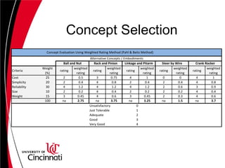
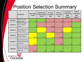
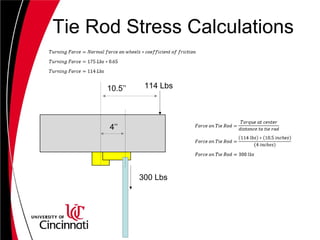
Baja Steering System Design
By: Adam M Conrad
IntroductionCurrent State
•No Steering System in Place
•Original Mount is Present
•Steering wheel mount is present
•No suspension in place
Goals for Project
•Design a steering system that utilizes
as much of the current frame
•System must be able to withstand SAE
racing conditions
•System should provide a competitive
advantage
Customer Requirement
Requirement Description Importance Rating
Reliability
The design must be able to perform under racing
conditions. 30%
Cost
The cost needs to be low and fall within the
customers budget 25%
simplicity
The design should be simple enough to build
given the resources and materials that the design
team has access to.
20%
Weight
The weight needs to be low in order to provide a
favorable power to weight ratio 15%
Size
The size of the assembly must be small enough to
accomadate the driver given the materials at
hand
10%
Circulating Ball Worm-gear
Strengths
• High Reliability
• Low Friction
Weaknesses
• Low simplicity
• Heavier
Rack and Pinion Concept
Strengths
• High Reliability
• High Simplicity
• Low Weight
Weaknesses
• Fast-Ratio rack
and pinions are
more expensive
Pitman Arm Linkage
Strengths
• Low Cost
• Low Weight
• High Reliability
Weaknesses
• Low Simplicity
• Unfavorable size
Steer-By-Wire
Strengths
• none
Weaknesses
• Low Simplicity
• Low Reliability
• Expensive
• Takes up a lot of
space
• Heavy
Double Crank Rocker
Strengths
• Low Cost
• High Simplicity
• Low weight
• Takes up little
space
Weaknesses
• Questionable
reliability
Concept Selection
Criteria
Weight
(%)
rating
weighted
rating
rating
weighted
rating
rating
weighted
rating
rating
weighted
rating
rating
weighted
rating
Cost 25 2 0.5 3 0.75 4 1 0 0 4 1
Simplicity 20 2 0.4 4 0.8 2 0.4 2 0.4 4 0.8
Reliability 30 4 1.2 4 1.2 4 1.2 2 0.6 3 0.9
Size 10 2 0.2 4 0.4 2 0.2 2 0.2 4 0.4
Weight 15 3 0.45 4 0.6 3 0.45 2 0.3 4 0.6
100 na 2.75 na 3.75 na 3.25 na 1.5 na 3.7
Unsatisfactory 0
Just Tolerable 1
Adequate 2
Good 3
Very Good 4
Crank Rocker
Alternative Concepts / Embodiments
Concept Evaluation Using Weighted Rating Method (Pahl & Beitz Method)
Ball and Nut Rack and Pinion Linkage and Pitarm Steer by Wire
Criteria for Rack Location
• Low Transmission Angle
– 30 degrees or below
– reduce bending moments
– reduce needed effort for turning
• Small Tie Rod Length
– 14 inches or below
– Low Material Costs
– Reduce buckling
• Low Turn Radius
– 8 feet or below
Location Concept 1
• 12 Inch Tie Rods
• Dismissed because of tie
rods exposure
• Dismissed because
steering shaft exposure
• Wheels pushed forward
• Rack Mounted on the front of vehicle
• 14 Inch Rack (12 to 1 Steering Ratio)
Location Concept 2
• Wheels pushed forward
• Rack Mounted in original mounting Location
• 14 inch rack (12 to 1 Steering Ratio)
• 50 degree horizontal
transmission angle
• 4 degree vertical
transmission angle
• 21 inch tie rods
• 17.3 foot turn radius
Location Concept 3
• New Control Arms
• Rack Mounted in original mounting Location
• 14 inch rack (12 to 1 Steering Ratio)
• 30 degree horizontal
transmission angle
• 5 degree vertical
transmission angle
• 15 inch tie rods
• 11.17 foot turn
radius
Location Concept 4
• New Control Arms
• Rack Mounted 5 inches forward from original mounting Location
• 16.25 inch rack (12 to 1 Steering Ratio)
• 12 degree Horizontal
transmission angle
• 7 degree Vertical
transmission angle
• 12 inch tie rods
• 8.75 foot turn radius
• 15.08 foot radius
with half turn
Location Concept 5
• New Control Arms
• Rack Mounted 7 inches forward from original mounting Location
• 16.25 inch rack (12 to 1 steering ratio)
• 0 degree Horizontal
transmission angle
• 10 degree Vertical
transmission angle
• 12 inch tie rods
• 6.978 foot turn
radius
• 13.08 foot radius
with half turn
Location Concept 6
• New Control Arms
• Rack Mounted 7 inches forward from original mounting Location
• 11.25 inch Rack (6.4 to 1 steering ratio)
• 0 degree Horizontal
transmission angle
• 9 degree Vertical
transmission angle
• 13 inch tie rods
• 5.33 foot turn radius
Position Selection Summary
Description
Rack Length
"Inches"
Approximate
Tie Rod Length
"Inches"
Lock-Lock
Turn Radius
"feet"
Half Turn,
Turn radius
"feet"
Horizontal
Transmission
Angle
"degrees"
Vertical
Transmission
angle
"degrees"
Concept 1
Wheels forward,
Rack in front 14 12 na na na na
Concept 2
Wheels forward,
rack in original
mount 14 21 17.294 na 50 4
Concept 3
New Control Arms,
Original Mount
14 15 11.17 na 30 5
Concept 4
New Control Arms,
Moved forward
16.25 12 8.75 15.08 12 7
Concept 5
New Control Arms,
Moved forward and
horizontal
16.25 11 6.978 13.08 0 10
Concept 6
New Control Arms,
Concept 5 with fast
ratio rack
11.25 13 5.3324 5.3324 0 9
Final Selection
Final Selection
Bump Steering Check
• Approximately
Halfway between
control arms
• 2 inch clearance
Tie Rod Material Selection
• Length: 13 inches
• Diameter: 3/4 inches
• Hole Diameter: 5/16 inches
• Threading: UNC 24
• Material: 6351 aluminum
(Yield at 40,000 PSI)
• Cost:
Tie Rod Stress Calculations
114 Lbs10.5’’
4’’
300 Lbs
Tie Rod Stress Calculations
300 Lbs
9 degrees
304 Lbs
Steering Shaft Material
Selection
• Length: 25 Inches
• Diameter: 5/8 Inches
• Material: Mild Carbon Steel
Component List
• Heim Joints (2)
• Clevis Rod End (2)
• Tie Rod Ends (2)
• 13’’ Aluminum Threaded Tie Rods
• 25’’ Mild Steel Steering Shaft
• Steering Wheel
• Fasteners
Questions?

Senior Design Presentation

  • 1.
    Baja Steering SystemDesign By: Adam M Conrad
  • 2.
    IntroductionCurrent State •No SteeringSystem in Place •Original Mount is Present •Steering wheel mount is present •No suspension in place Goals for Project •Design a steering system that utilizes as much of the current frame •System must be able to withstand SAE racing conditions •System should provide a competitive advantage
  • 3.
    Customer Requirement Requirement DescriptionImportance Rating Reliability The design must be able to perform under racing conditions. 30% Cost The cost needs to be low and fall within the customers budget 25% simplicity The design should be simple enough to build given the resources and materials that the design team has access to. 20% Weight The weight needs to be low in order to provide a favorable power to weight ratio 15% Size The size of the assembly must be small enough to accomadate the driver given the materials at hand 10%
  • 4.
    Circulating Ball Worm-gear Strengths •High Reliability • Low Friction Weaknesses • Low simplicity • Heavier
  • 5.
    Rack and PinionConcept Strengths • High Reliability • High Simplicity • Low Weight Weaknesses • Fast-Ratio rack and pinions are more expensive
  • 6.
    Pitman Arm Linkage Strengths •Low Cost • Low Weight • High Reliability Weaknesses • Low Simplicity • Unfavorable size
  • 7.
    Steer-By-Wire Strengths • none Weaknesses • LowSimplicity • Low Reliability • Expensive • Takes up a lot of space • Heavy
  • 8.
    Double Crank Rocker Strengths •Low Cost • High Simplicity • Low weight • Takes up little space Weaknesses • Questionable reliability
  • 9.
    Concept Selection Criteria Weight (%) rating weighted rating rating weighted rating rating weighted rating rating weighted rating rating weighted rating Cost 252 0.5 3 0.75 4 1 0 0 4 1 Simplicity 20 2 0.4 4 0.8 2 0.4 2 0.4 4 0.8 Reliability 30 4 1.2 4 1.2 4 1.2 2 0.6 3 0.9 Size 10 2 0.2 4 0.4 2 0.2 2 0.2 4 0.4 Weight 15 3 0.45 4 0.6 3 0.45 2 0.3 4 0.6 100 na 2.75 na 3.75 na 3.25 na 1.5 na 3.7 Unsatisfactory 0 Just Tolerable 1 Adequate 2 Good 3 Very Good 4 Crank Rocker Alternative Concepts / Embodiments Concept Evaluation Using Weighted Rating Method (Pahl & Beitz Method) Ball and Nut Rack and Pinion Linkage and Pitarm Steer by Wire
  • 10.
    Criteria for RackLocation • Low Transmission Angle – 30 degrees or below – reduce bending moments – reduce needed effort for turning • Small Tie Rod Length – 14 inches or below – Low Material Costs – Reduce buckling • Low Turn Radius – 8 feet or below
  • 11.
    Location Concept 1 •12 Inch Tie Rods • Dismissed because of tie rods exposure • Dismissed because steering shaft exposure • Wheels pushed forward • Rack Mounted on the front of vehicle • 14 Inch Rack (12 to 1 Steering Ratio)
  • 12.
    Location Concept 2 •Wheels pushed forward • Rack Mounted in original mounting Location • 14 inch rack (12 to 1 Steering Ratio) • 50 degree horizontal transmission angle • 4 degree vertical transmission angle • 21 inch tie rods • 17.3 foot turn radius
  • 13.
    Location Concept 3 •New Control Arms • Rack Mounted in original mounting Location • 14 inch rack (12 to 1 Steering Ratio) • 30 degree horizontal transmission angle • 5 degree vertical transmission angle • 15 inch tie rods • 11.17 foot turn radius
  • 14.
    Location Concept 4 •New Control Arms • Rack Mounted 5 inches forward from original mounting Location • 16.25 inch rack (12 to 1 Steering Ratio) • 12 degree Horizontal transmission angle • 7 degree Vertical transmission angle • 12 inch tie rods • 8.75 foot turn radius • 15.08 foot radius with half turn
  • 15.
    Location Concept 5 •New Control Arms • Rack Mounted 7 inches forward from original mounting Location • 16.25 inch rack (12 to 1 steering ratio) • 0 degree Horizontal transmission angle • 10 degree Vertical transmission angle • 12 inch tie rods • 6.978 foot turn radius • 13.08 foot radius with half turn
  • 16.
    Location Concept 6 •New Control Arms • Rack Mounted 7 inches forward from original mounting Location • 11.25 inch Rack (6.4 to 1 steering ratio) • 0 degree Horizontal transmission angle • 9 degree Vertical transmission angle • 13 inch tie rods • 5.33 foot turn radius
  • 17.
    Position Selection Summary Description RackLength "Inches" Approximate Tie Rod Length "Inches" Lock-Lock Turn Radius "feet" Half Turn, Turn radius "feet" Horizontal Transmission Angle "degrees" Vertical Transmission angle "degrees" Concept 1 Wheels forward, Rack in front 14 12 na na na na Concept 2 Wheels forward, rack in original mount 14 21 17.294 na 50 4 Concept 3 New Control Arms, Original Mount 14 15 11.17 na 30 5 Concept 4 New Control Arms, Moved forward 16.25 12 8.75 15.08 12 7 Concept 5 New Control Arms, Moved forward and horizontal 16.25 11 6.978 13.08 0 10 Concept 6 New Control Arms, Concept 5 with fast ratio rack 11.25 13 5.3324 5.3324 0 9
  • 18.
  • 19.
  • 20.
    Bump Steering Check •Approximately Halfway between control arms • 2 inch clearance
  • 21.
    Tie Rod MaterialSelection • Length: 13 inches • Diameter: 3/4 inches • Hole Diameter: 5/16 inches • Threading: UNC 24 • Material: 6351 aluminum (Yield at 40,000 PSI) • Cost:
  • 22.
    Tie Rod StressCalculations 114 Lbs10.5’’ 4’’ 300 Lbs
  • 23.
    Tie Rod StressCalculations 300 Lbs 9 degrees 304 Lbs
  • 24.
    Steering Shaft Material Selection •Length: 25 Inches • Diameter: 5/8 Inches • Material: Mild Carbon Steel
  • 25.
    Component List • HeimJoints (2) • Clevis Rod End (2) • Tie Rod Ends (2) • 13’’ Aluminum Threaded Tie Rods • 25’’ Mild Steel Steering Shaft • Steering Wheel • Fasteners
  • 26.