INTRODUCTION
WHAT IS ANATV?
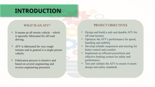
• It means an all terrain vehicle – which
is specially fabricated for off road
driving.
• ATV is fabricated for very rough
terrains and in general is a single person
vehicle.
• Fabrication process is iterative and
based on several engineering and
reverse engineering processes
PROJECT OBJECTIVES
• Design and build a safe and durable ATV for
off road terrains
• Optimize the ATV’s performance for speed,
handling and stability
• Develop reliable suspension and steering for
better control and comfort
• Implement an efficient powertrain and
effective braking system for safety and
performance
• Test and validate the ATV to ensure it meets
design and safety standards.
3.
ATV’24 vs ATV’25
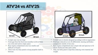
56inch
58 inch
• Cockpit area was too large
• Front gap from the front most member to driver toeas
was extra and useless empty space
• Rear engine compartment area was smaller and
difficult to fit parts
• There were two base panels to keep propeller shaft in
between
• Cockpit area is closely designed according to driver ergonomics
• Front gap reduced so as to fit differential, steering and brakes
components smartly in less area
• Rear engine compartment area is kept wide and spacious to fit
splash shield and other parts safely
• Only one belly panel is kept thus reducing extra material and
weight.
54 inch
56 inch
4.
Lessons Learnt
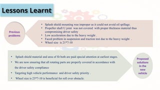
Previous
problems
• Splashshield mounting was improper as it could not avoid oil spillage.
• Propeller shaft U joint was not covered with proper thickness material thus
compromising driver safety
• Low acceleration due to the heavy weight .
• Faced problem in suspension and traction test due to the heavy weight .
• Wheel size is 21*7-10
Proposed
solutions
in the
new
vehicle
• Splash shield material and area of fit both are paid special attention at earliest stages.
• We are now ensuring that all rotating parts are properly covered in accordance with
the driver safety compliance
• Targeting high vehicle performance and driver safety priority .
• Wheel size is 23*7-10 is beneficial for roll over obstacle.
5.
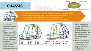
CHASSIS
The structural frameworkof the ATV, designed to protect the driver during
rollovers or impacts and provide a foundation for mounting other
components like the suspension, engine, and body panels.
It is crucial for the vehicle’s overall safety and structural integrity
CHASSIS
ROLL CAGE
NAMED POINTS
FRAME
MEMBER
• Main structural
components that form
the core of the roll
cage.
• They are responsible
for the overall strength
and integrity of the
structure, especially in
the event of a rollover
or collision.
• They must be designed
and positioned to
provide maximum
protection to the driver.
• These components
provide additional
support and
reinforcement to the
primary members but
are not as critical in
absorbing impact
forces.
• Enhance the rigidity
and stability of the
overall structure and
help mount other
components.
6.
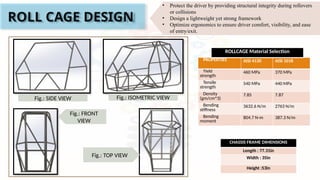
ROLL CAGE DESIGN
PROPERTIESAISI 4130 AISI 1018
Yield
strength
460 MPa 370 MPa
Tensile
strength
540 MPa 440 MPa
Density
(gm/cm^3)
7.85 7.87
Bending
stiffness
3632.6 N/m 2763 N/m
Bending
moment
804.7 N-m 387.3 N/m
ROLLCAGE Material Selection
CHASSIS FRAME DIMENSIONS
Length : 77.31in
Width : 35in
Height :53in
Fig.: SIDE VIEW Fig.: ISOMETRIC VIEW
Fig.: FRONT
VIEW
Fig.: TOP VIEW
• Protect the driver by providing structural integrity during rollovers
or collisions
• Design a lightweight yet strong framework
• Optimize ergonomics to ensure driver comfort, visibility, and ease
of entry/exit.
7.
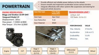
POWERTRAIN
ENGINE SPECIFICATION :
Briggsand Stratton 10 HP OHV
Vanguard Model 19
Displacement : 305cc
Max power : 7.35KW @3800
Max Torque : 19.6 Nm @2800
Gear Box type Two Stage
Reduction
Gear type Spur Gear
Gear Reduction 9.22
Gear Material EN24
CVTech CVT
CVT Ratio : 0.4 to 3.1
TRANSMISSION UNIT :
Engine CVT
Stage 2
reduction
(3.4:1)
Differential
(3.5:1)
Wheel
Stage 1
reduction
(2.7:1)
PERFORMANCE VALUE
Max. Velocity 57 km/hr.
Acceleration 5.06 m/s^2
Gradeability 51.6%
Efficiency 76%
• Provide efficient and reliable power delivery to the wheels
• Ensure smooth and responsive acceleration across various terrains
• Integrate effectively with other systems like suspension and steering for
balanced vehicle dynamics
8.
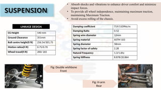
SUSPENSION
Fig: H-arm
Rear
Fig: Doublewishbone
Front
LINKAGE DESIGN
CG Height 540 mm
Ground Clearance 351mm
Roll centre height(F/R) 256.54/301.75
Motion ratios(F/R) 0.75/0.70
Wheel travel(F/R) 200/ 265
• Absorb shocks and vibrations to enhance driver comfort and minimize
impact forces.
• To provide all wheel independence, maintaining maximum traction,
maintaining Maximum Traction.
• Avoid excess rolling of the chassis.
Damping coefficient 719/1109Ns/m
Damping Ratio 0.52
Spring wire diameter 12mm
Spring material ASTM 103
Spring diameter 58mm
Spring factor of safety 2.28
Natural Frequency 1.3/1.6hz
Spring Stiffness 8.878/20.864
9.
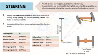
STEERING
• Provide preciseand responsive control for maneuvering
• Ensure stability and predictability during high-speed and low-speed turns.
• Minimize steering effort while maximizing driver feedback and comfort
Track Width
54 Inch
Wheel
Base
56
Inch
Fig.: Ackerman geometry
Steering ratio 4:1
Rack Travel 99.88 mm
Pinion Diameter 44.06 mm
Turns(Lock to Lock) 1.44 Turn
Steering angle (in) 40 deg.
Steering angle (out) 24.87 deg.
Column Type Fixed
Wheel Diameter 300mm
Ackerman angle 46.3 deg.
Ackerman % 35.6
Opting for Ackermann Geometry because it is beneficial
during Sharp Turning and reduces Steering Efforts. This
helps in maneuverability.
Considered Over-Steer geometry to achieve high Turning
Circle.
10.
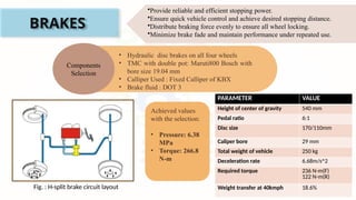
BRAKES
•Provide reliable andefficient stopping power.
•Ensure quick vehicle control and achieve desired stopping distance.
•Distribute braking force evenly to ensure all wheel locking.
•Minimize brake fade and maintain performance under repeated use.
Components
Selection
• Hydraulic disc brakes on all four wheels
• TMC with double pot: Maruti800 Bosch with
bore size 19.04 mm
• Calliper Used : Fixed Calliper of KBX
• Brake fluid : DOT 3
PARAMETER VALUE
Height of center of gravity 540 mm
Pedal ratio 6:1
Disc size 170/110mm
Caliper bore 29 mm
Total weight of vehicle 250 kg
Deceleration rate 6.68m/s^2
Required torque 236 N-m(F)
122 N-m(R)
Weight transfer at 40kmph 18.6%
Achieved values
with the selection:
• Pressure: 6.38
MPa
• Torque: 266.8
N-m
Fig. : H-split brake circuit layout