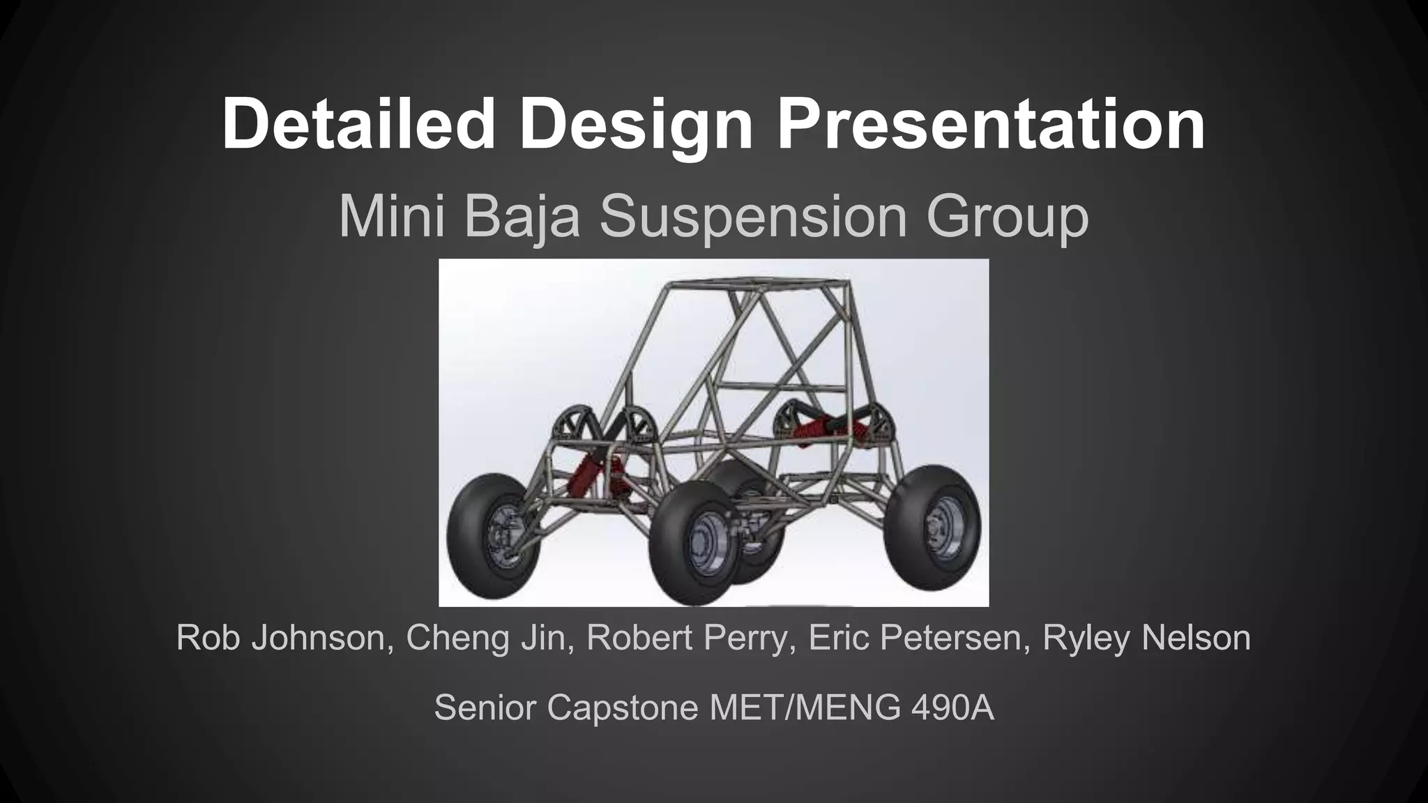
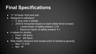
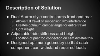
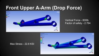
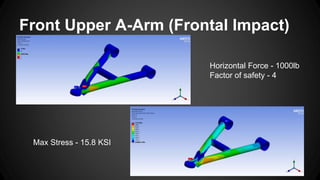
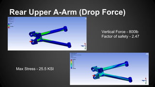
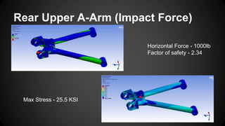
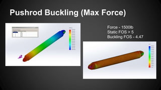
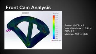
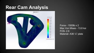
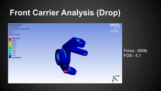
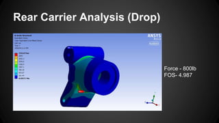
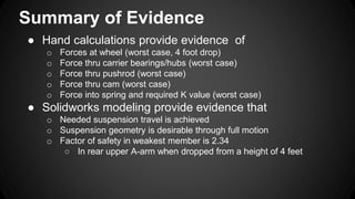
Detailed Design Presentation
Mini Baja Suspension Group
Rob Johnson, Cheng Jin, Robert Perry, Eric Petersen, Ryley Nelson
Senior Capstone MET/MENG 490A
Introduction
Baja Suspension Team
● Design and Build Suspension System for
Eastern’s SAE Mini Baja Vehicle
Needs, Functions, and Features
● Minimum 10” of travel, front and rear
● Adjustability:
o Ride Height
o Suspension Stiffness
● Sustain 3’ jump without bottoming out
shocks or breaking related components
Final Specifications
● 11” of travel, front and rear
● Designed to withstand:
o 4’ drop onto 4 wheels
o 2000 lb horizontal impact on each wheel (front to back)
○ Lowest factor of safety present: 2.34
○ Maximum factor of safety present: 5.1
● k values for shocks:
o Front: 160 lbs/in
o Rear: 200 lbs/in
● Ride height (distance from lowest point of vehicle to ground):
o Max: 17 3/16”
o Min: 10”
Description of Solution
● Dual A-arm style control arms front and rear
o Allows full travel of suspension w/o interference
o Creates optimum camber angle for entire travel
o Light weight
● Adjustable ride stiffness and height
o Location of pushrod connection on cam dictates this
● Designed optimum geometry so that each
component can withstand required loads
Front Upper A-Arm (Drop Force)
Vertical Force - 800lb
Factor of safety - 2.764
Max Stress - 22.8 KSI
Front Upper A-Arm (Frontal Impact)
Horizontal Force - 1000lb
Factor of safety - 4
Max Stress - 15.8 KSI
Rear Upper A-Arm (Drop Force)
Vertical Force - 800lb
Factor of safety - 2.47
Max Stress - 25.5 KSI
Rear Upper A-Arm (Impact Force)
Horizontal Force - 1000lb
Factor of safety - 2.34
Max Stress - 25.5 KSI
Pushrod Buckling (Max Force)
Force - 1500lb
Static FOS > 5
Buckling FOS - 4.47
Front Cam Analysis
Force - 1500lb x 2
Von Mises Max - 12.9 ksi
FOS- 2.8
Material- A36 ¼” plate
Rear Cam Analysis
Force - 1500lb x 2
Max Von Mises - 13.8 ksi
FOS- 2.6
Material- A36 ¼” plate
Front Carrier Analysis (Drop)
Force - 800lb
FOS - 5.1
Rear Carrier Analysis (Drop)
Force - 800lb
FOS- 4.987
Summary of Evidence
● Hand calculations provide evidence of
o Forces at wheel (worst case, 4 foot drop)
o Force thru carrier bearings/hubs (worst case)
o Force thru pushrod (worst case)
o Force thru cam (worst case)
o Force into spring and required K value (worst case)
● Solidworks modeling provide evidence that
o Needed suspension travel is achieved
o Suspension geometry is desirable through full motion
o Factor of safety in weakest member is 2.34
○ In rear upper A-arm when dropped from a height of 4 feet
Budget and cost analysis
Schedule of Milestones and Major Tasks
Start: April 1, 2015
Finish: May 29, 2015
Questions?

Final Detailed Design

  • 1.
    Detailed Design Presentation MiniBaja Suspension Group Rob Johnson, Cheng Jin, Robert Perry, Eric Petersen, Ryley Nelson Senior Capstone MET/MENG 490A
  • 2.
    Introduction Baja Suspension Team ●Design and Build Suspension System for Eastern’s SAE Mini Baja Vehicle
  • 3.
    Needs, Functions, andFeatures ● Minimum 10” of travel, front and rear ● Adjustability: o Ride Height o Suspension Stiffness ● Sustain 3’ jump without bottoming out shocks or breaking related components
  • 4.
    Final Specifications ● 11”of travel, front and rear ● Designed to withstand: o 4’ drop onto 4 wheels o 2000 lb horizontal impact on each wheel (front to back) ○ Lowest factor of safety present: 2.34 ○ Maximum factor of safety present: 5.1 ● k values for shocks: o Front: 160 lbs/in o Rear: 200 lbs/in ● Ride height (distance from lowest point of vehicle to ground): o Max: 17 3/16” o Min: 10”
  • 5.
    Description of Solution ●Dual A-arm style control arms front and rear o Allows full travel of suspension w/o interference o Creates optimum camber angle for entire travel o Light weight ● Adjustable ride stiffness and height o Location of pushrod connection on cam dictates this ● Designed optimum geometry so that each component can withstand required loads
  • 7.
    Front Upper A-Arm(Drop Force) Vertical Force - 800lb Factor of safety - 2.764 Max Stress - 22.8 KSI
  • 8.
    Front Upper A-Arm(Frontal Impact) Horizontal Force - 1000lb Factor of safety - 4 Max Stress - 15.8 KSI
  • 9.
    Rear Upper A-Arm(Drop Force) Vertical Force - 800lb Factor of safety - 2.47 Max Stress - 25.5 KSI
  • 10.
    Rear Upper A-Arm(Impact Force) Horizontal Force - 1000lb Factor of safety - 2.34 Max Stress - 25.5 KSI
  • 11.
    Pushrod Buckling (MaxForce) Force - 1500lb Static FOS > 5 Buckling FOS - 4.47
  • 12.
    Front Cam Analysis Force- 1500lb x 2 Von Mises Max - 12.9 ksi FOS- 2.8 Material- A36 ¼” plate
  • 13.
    Rear Cam Analysis Force- 1500lb x 2 Max Von Mises - 13.8 ksi FOS- 2.6 Material- A36 ¼” plate
  • 14.
    Front Carrier Analysis(Drop) Force - 800lb FOS - 5.1
  • 15.
    Rear Carrier Analysis(Drop) Force - 800lb FOS- 4.987
  • 16.
    Summary of Evidence ●Hand calculations provide evidence of o Forces at wheel (worst case, 4 foot drop) o Force thru carrier bearings/hubs (worst case) o Force thru pushrod (worst case) o Force thru cam (worst case) o Force into spring and required K value (worst case) ● Solidworks modeling provide evidence that o Needed suspension travel is achieved o Suspension geometry is desirable through full motion o Factor of safety in weakest member is 2.34 ○ In rear upper A-arm when dropped from a height of 4 feet
  • 17.
  • 18.
    Schedule of Milestonesand Major Tasks Start: April 1, 2015 Finish: May 29, 2015
  • 19.