
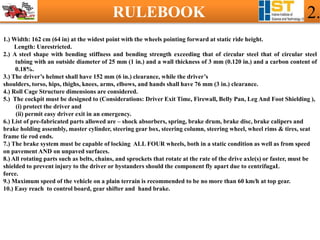
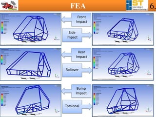

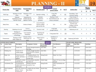
![STEERING - II 12.
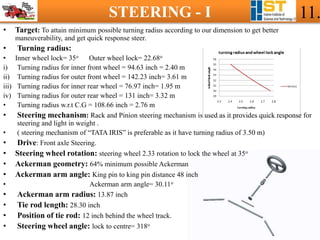
• Return ability
Mv = -(Fzl + Fzr) (d sin δ)sin Ѱ+ (Fzl -Fzr) (d cosδ) sinν
= 2.230Nm (when δ is steered negative ) &
= -0.8827Nm (when δ is steered positive )
• Static Camber, Υ̻: 0.75
• Camber angle equation :
Υ=Υ̻+ Ѱ+ −1[(sin Ѱ) x co s δ] + −1[(sinν) x sin δ] -180ο
• Caster ,ν: 5ο
• Toe in: 3mm
• Steering angle inclination:](https://image.slidesharecdn.com/15124indoreinstituteofsciencetechnology-iiindorevirtualpresentation-180310172949/85/BAJA-SAE-INDIA-2015-12-320.jpg)
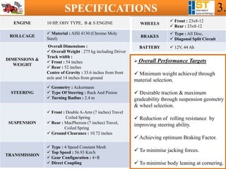
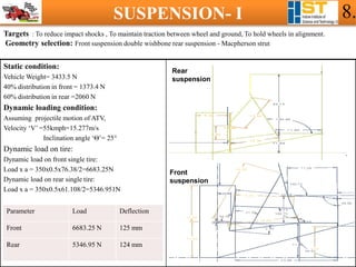
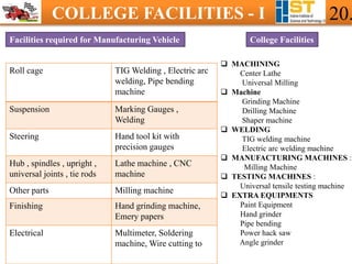
![BRAKES - I 13.
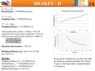
TARGET: To design an efficient brake assembly by which we can achieve minimum pedal force, minimum
stopping distance, with maximum braking torque.
BRAKE SELECT: Disc brake of 200 mm diameter, diagonal split circuit.
DIAGONAL SPLIT CIRCUIT
CALCULATIONS:
W = 350 x 9.81 = 3433.5 N
µ = 0.7
l = 56 inches
Pedal Force = 100 N
Fbp = Fd x [ L2 / L1 ]
Brake Pedal Force = 550 N
Pmc = [ Fbp / Amc ]
Pressure at master cylinder = 2.73 x 10⁶ N/m2
Pcal = Pmc
Fclamp = Pcal x Acal
Fclamp = 2631.539682 N
Fclamp = Fcal x 2
Total force at caliper = 5263.079364 N
Ffriction = Fclamp x µbp
Total friction force at Caliper = 2105.231746 N
Tr = Ffriction x Reff
Torque at rotor = 202.8917095 N-m
Torque at rotor = Torque at wheel
Ftire = ( Tt / Rt )
Ftire = 694.5967459 N
Ftotal = 694.5967459 x 4
Total braking force at all wheels = 2778.386984 N](https://image.slidesharecdn.com/15124indoreinstituteofsciencetechnology-iiindorevirtualpresentation-180310172949/85/BAJA-SAE-INDIA-2015-13-320.jpg)
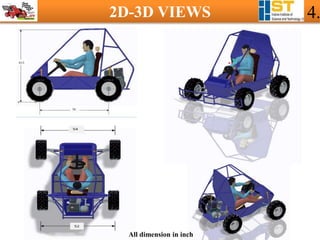
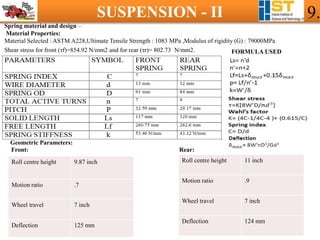
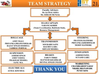
![POWERTRAIN - II 16.
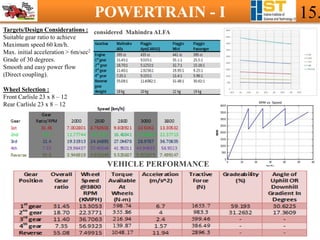
Basic Calculations :
Maximum Vehicle Speed = (2*π*3800*.2921*60)/(1000*7.35) = 56.93 km/h
Maximum Acceleration = 550*32.2*10/12.11*661.38 = 6.7 m/s2
Torque at Clutch = Te-Ie αe = 19.04 Nm
Maximum Torque Output to driveshaft / wheels = (19.04-.0000001034*18096.4)*31.45 = 598.74 Nm
Maximum Tractive Force = 19.2*.85*31.45/.2921 = 1757.15 N [Taking transmission efficiency = 85%]
Gradeabilty or Max Gradient = 59.193 % = α = 30.6225 degrees. Tractive Curve
Adapter & Coupler : The crankshaft of the engine has diameter of
25.4 mm,a keyway for 1” square key, whereas splines are at
the gearbox side of diameter of 20 mm at. Hence, an adapter has
been designed with an internal keyway on the engine side and external
splines on the gearbox side. The axial length of the designed Coupler
is kept to be 42 mm
Designed Adapter Creo Image of Coupler Assembly Powertrain Model
Mountings :
The engine is to be mounted in the rear of the roll cage on pipes of rectangular cross section using rubber bushings.
For the gearbox mounting, the standard mounting bracket is to be utilized.](https://image.slidesharecdn.com/15124indoreinstituteofsciencetechnology-iiindorevirtualpresentation-180310172949/85/BAJA-SAE-INDIA-2015-16-320.jpg)
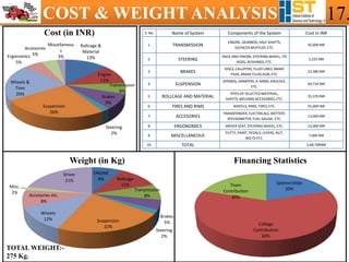


1. The document outlines the design specifications and rules for an all-terrain vehicle (ATV) racing competition. It includes requirements for dimensions, materials, driver safety, speeds, and allowed pre-fabricated parts. 2. Detailed specifications are provided for the vehicle's 10HP engine, roll cage made of chromoly steel, dimensions, weights, double wishbone front and rear suspension systems, rack and pinion steering, disc brakes, and 4-speed transmission. 3. Performance targets include minimum weight, desirable traction, maximum gradeability, reduced rolling resistance, and optimized braking. 2D drawings and 3D models illustrate the vehicle design.


