1. Baja Buggy Technical Details
1. 1. BAJA SAE INDIA 2014 VIRTUAL ROUND TEAM VIKRAM Babu Banarasi
Das National Institute of Technology & Management Lucknow , Uttar Pradesh
Northern Section
2. 2. TEAM LEADER DESIGN & ANALYSIS TEAM Steering Roll cage
Suspension MANUFACTURING TEAM FINANCE Fabrication Parts
Procurement Jigs & FixturesBrakes Budgeting & Cost Estimations Market
Survey Marketing and PR Transmission Engine & Electricals Modeling &
Simulation SPONSORSHIP Ergonomics & Aesthetics TEAM FORMULATION
TEAM SIZE :- 25 MEMBERS Design Input by: BAJASAE 2014 Rulebook
Modelling on: PRO-E WILDFIRE 5.0 FEA Constraints formulation on : ANSYS
14.5 & ALTAIR HYPERWORKS
3. 3. Technical Specifications Parameter Value Vehicle length 2500 mm Vehicle
width 1556.4 +00 +50 mm Ground clearance 254 mm Vehicle height 1534.25
mm Roll cage material Carbon Steel (AISI 1018) Tube dimension 25.4 mm
outer dia. 3mm inner dia. Roll cage mass 22 kg Total mass 350 kg approx.
Parameter Value Battery 12V/44 Ah Suspension Front Rear Double
Wishbone Double Wishbone Damper mounting Lower arm Upper arm Max
speed 58 km/h Brake Front Rear Disc Disc Steering Rack and pinion Tyres 22
X 8 – 10
4. 4. Roll Cage Design Methodolgy: • Driver oriented rollcage design. • Light
weight, compact and simple. • Ease of egress during accident. • Members are
kept short by optimum triangulation to have a good load transfer path. • Frame
is designed to be stiff for loads like bending and torsional. • Material is kept
farther from rotating axis to increase stiffness. • Polar moment of inertia is
maximised. Total number of weld joints: 48 Width of Rollcage: 750 mm Length
of Rollcage: 2500 mm Height of Rollcage: 1280.25 mm Material Used: Carbon
Steel (AISI 1018) • UTS: 365 Mpa • Carbon content: 0.18% • Outer Diameter:
25.4mm • Wall Thickness: 3mm (primary members) 0.89mm(secondary
members)
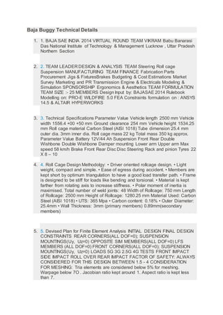
5. 5. Devised Plan for Finite Element Analysis INITIAL DESIGN FINAL DESIGN
CONSTRAINTS REAR CORNERS(ALL DOF=0); SUSPENSION
MOUNTINGS(Uy, Uz=0) OPPOSITE SIM MEMBERS(ALL DOF=0) LFS
MEMBERS (ALL DOF=0) FRONT CORNERS(ALL DOF=0); SUSPENSION
MOUNTINGS(Uy, Uz=0) LOADS 5G 3G 2.5G 4G TESTS FRONT IMPACT
SIDE IMPACT ROLL OVER REAR IMPACT FACTOR OF SAFETY: ALWAYS
CONSIDERED FOR THIS DESIGN BETWEEN 1.5 - 4 CONSIDERATION
FOR MESHING: Tria elements are considered below 5% for meshing.
Warpage below 7O . Jacobian ratio kept around 1. Aspect ratio is kept less
than 7.
2. 6. 6. Steering The steering system allows the driver to control the direction of
vehicle travel. This is made possible by linkage that connects the steering
wheel to the steerable wheels and tires. Types of steering: 1.Recirculating ball
steering gear 2.Rack and pinion gear 3.Worm and Sector We are using the
Rack and Pinion gear system. Design selection criteria: We are using the rack
and pinion gear system just because due to its low cost, its better
compatibility with our compact design and its simple construction. We are
using the manual steering system, so it will help us for immediate response.
CALCULATIONS : Wheel base - 1800mm Track width - 1250mm Lock to lock
ratio - 3 Steering ratio - 16:1 Ideal Ackerman angle - 19.15 Actual Ackerman
angle- 7.660 Inner angle(i) – 37.590 Outer angle(o)- 29.93o Turning Radius-
2963mm Caster- 5o negative Camber- 2o positive
7. 7. Braking System • The brake system consists of four wheel disc brakes
actuated by two independent master cylinders. The brake pedal uses a 6.2:1
pedal ratio . • The brake callipers chosen are single piston floating type
callipers of Honda Aviator and Bajaj Pulsar220 . • DOT 4 brake fluid will be
used for braking purpose Specifications Pedal ratio = 6.2:1 Pedal size = 7.75”
Braking percentage = 62:38 Master cylinder type: Two random master
cylinders of Maruti 800 and a balance bar. Brake lines: maruti 800 brake lines
and hoses Calliper type: single piston floating-type callipers of Honda Aviator
and Bajaj Pulsar 220 Calliper cup size = 1.5” Rotor type: ventilated Rotor size
= 7.48”(190 mm ) Rotor thickness = 4mm
8. 8. f = 7.84m/s2 Rf = 2121.45N and Rr = 1308.54N. this will be the front wheel
and rear wheel reactions. after a hard braking on level track, producing a
deceleration of 6.87 m/s2 • STOPING DISTANCE SPEED (Km/Hr) Stopping
Distance(m) Braking Time(s) 30 4.42 1.06 40 7.87 1.42 50 12.30 1.78 58
16.55 2.05
9. 9. Ergonomics & Safety Features Ergonomics refers to the relationship
between people and their working environment, so in our vehicle the
perspective of ergonomics has been considered over 4 points: 1. Vision 2.
Ease of egress 3. Additional Controls
10.10. POWER TRAIN TRANSMISSION Manual transmission needed gear shift
which would require some area near driver seat and thus increases the
dimension of buggy. So we decided to go for cvt transmission. Pulley based
CVT is the most affordable and simple one. It consist of two pulleys.primary
pulley connected to engine and secondary pulley connected to axle.These
two pulleys are connected by a rubber V belt. Variation in the pitch radii of
these pulleys lead to the change in the gear ratio. CVT Transmission option
available : 1.Mahindra alfa cvt. 2.Polaris p90 cvt. We are opting Mahindra
ALFA because of its well known coupling with B&S Engine and its low cost.
Power train refers to the group of components that generate power and
deliver it to the wheels of vehicle. ENGINE SPECIFICATIONS Torque 14.50
ft-lbs Displacement 305 No. of cylinder Single Configuration Horizontal
3. Technology OHV Length 12.3 in Width 15.4 in Height 16.4 in Weight 50.4 lbs
Bore 3.12 in Stroke 2.4 in Engine Fuel Gasoline Spark Plug RC12YC
11.11. Suspension Design Criteria: Both the front and rear suspension system
are independent double wishbone(A-arm) suspension having unequal control
arms. It is chosen because 1: Wishbone suspension give more movement of
the tires and hence the vehicle. 2: In double A-arm suspension, force is
distributed at five points on the roll cage unlike at only one point in
macpherson strut. 3: It can be slightly adjusted for different parameters of
suspension tuning like chamber angle, ground clearance etc. The A-arms at
the front are pinned to the roll cage while at the knuckle end the arms are
attached using boll and socket joints. While at the rear as there is no
cornering requirement the A-arms are pinned both to the roll cage as well as
the knuckle. FRONT LOWER CONTROL ARMS LENGTH: 280 mm REAR
UPPER CONTROL ARMS LENGTH: 190 mm
12.12. Design Validation Plan
13.13. DESIGN MODE AND FAILURE EFFECT ANALYSIS
14.14. COLLEGE FACILITIES Centre lathe Milling Pipe bending Electric arc
welding Oxy-Acetylene Welding Drilling machine Shaper machine Power hack
saw Portable drilling machine Planer Machine 35% 11% 2% 8% 7% 6% 2%
13% 16% PIE CHART ENGINE & DRIVE TRANSMISSION STEERING
SUSPENSION FRAME & BODY BRAKES ELECTRICAL SAFETY
MISCELLANEOUS SUBSYSTEM MATERIALS EXTRAS TOTAL ENGINE &
DRIVE 70,000 - Rs. 70,000 TRANSMISSION 22,700 150 Rs. 22,850
STEERING 2,500 1,000 Rs. 3,500 SUSPENSION 11,000 4,500 Rs. 15,500
FRAME & Painting Then the roll cage is assembled with: 1.TYRES,
DAMPERS AND SUSPENSION 2.ENGINE SYSTEM 3.STEERING AND
BRAKES 4.DRIVER SEATPADDING 5.TRANSMISSION SYSTEM
MANUFACTURING PROCESSES REQUIRED Baking Drawing
Undercoating Inspection Welding Bending Pipe Cutting BODY
9,000 5,000 Rs. 14,000 BRAKES 10,000 1,580 Rs. 11,580 ELECTRICAL
4,370 - Rs. 4,370 SAFETY EQUIPMENT 25,890 - Rs. 25,890
MISCELLANEOUS - - Rs. 33,500 TOTAL Rs. 2,01,190 Cost Estimation
Processes in sequence of: