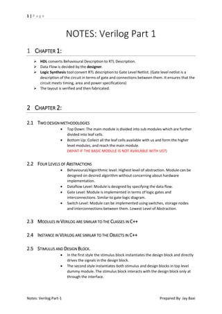
The PDF contains one of the six parts to learn Verilog in the simplest possible way.
It contains notes of first three chapters of the reference book Verilog HDL by Samir Palnitkar
Routing in Integrated circuits is an important task which requires extreme care while placing the modules and circuits and connecting them with each other.
A fundamental introduction to Intellectual Property in VLSI domain. Starts from basics and includes types of IPs and their examples, life cycle of an IP and other few topics in brief in an interactive Q-A manner.
The material is also available at : https://wordpress.com/stats/day/vlsifundamentals.wordpress.com
Verilog HDL is a hardware description language used to design and document electronic systems. Verilog HDL allows designers to design at various levels of abstraction. It is the most widely used HDL with a user community of more than 50,000 active designers.
A brief history
Verilog HDL originated at Automated Integrated Design Systems (later renamed as Gateway Design Automation) in 1985. The company was privately held at that time by Dr. Prabhu Goel, the inventor of the PODEM test generation algorithm. Verilog HDL was designed by Phil Moorby, who was later to become the Chief Designer for Verilog-XL and the first Corporate Fellow at Cadence Design Systems. Gateway Design Automation grew rapidly with the success of Verilog-XL and was finally acquired by Cadence Design Systems, San Jose, CA in 1989.
Verilog was invented as simulation language. Use of Verilog for synthesis was a complete afterthought. Rumors abound that there were merger discussions between Gateway and Synopsys in the early days, where neither gave the other much chance of success..
In the late 1980's it seemed evident that designers were going to be moving away from proprietary languages like n dot, HiLo and Verilog towards the US Depatment of Defense standard H.D.L., known as the VHSIC Hardware Description Language. VHSIC it self stands for "Very High Speen Intergrated Circuit" BTW).
Perhaps due to such market pressure, Cadence Design Systems decided to open the Verilog language to the public in 1990, and thus OVI (Open Verilog International) was born. Until that time, Verilog HDL was a proprietary language, being the property of Cadence Design Systems. When OVI was formed in 1991, a number of small companies began working on Verilog simulators, including Chronologic Simulation, Frontline Design Automation, and others. The first of these came to market in 1992, and now there are mature Verilog simulators available from many sources.
As a result, the Verilog market has grown substantially. The market for Verilog related tools in 1994 was well over $75,000,000, making it the most commercially significant hardware description language on the market.
An IEEE working group was established in 1993 under the Design Automation Sub-Committee to produce the IEEE Verilog standard 1364. Verilog became IEEE Standard 1364 in 1995.
As an international standard, the Verilog market continued to grow. In 1998 the market for Verilog simulators alone was well over $150,000,000; continuing its dominance.
The IEEE working group released a revised standard in March of 2002, known as IEEE 1364-2001. Significant publication errors marred this release, and a revised version was released in 2003, known as IEEE 1364-2001 Revision C.
Task and Function is the basic component of a programming language. Even on hardware Verification , those task and function is used. Task ans function provides a short way to repeatedly use the same block of code many times, This presentation gives you the basic information about Task and Function in Verilog. For more information on this, kindly contact us.
I made this presentation for you , I hope its useful for you all, and I hate Plagiarism please, I also used some slides here but I mentioned all in the last slide :)
Hope you can get benefits from it
Radiation Hardening by Design is one of the hardware based solution to one of the most troublesome problem faced by digital circuits in the space.
RHBD provides varieties of techniques to make the circuit resilient towards such effects and ensures proper malfunctioning of the circuit.
Notes: Verilog Part 2 - Modules and Ports - Structural Modeling (Gate-Level M...Jay Baxi
The Notes Verilog Part 2 includes the notes and keypoints of a reference book "Verilog HDL by Samir Palnitkar.
This is the second part out of the total six parts.
Notes: Verilog Part 4- Behavioural ModellingJay Baxi
This is the 4th part of the Verilog HDL notes prepared from Verilog HDL by Samir Palnitkar .
It contains a broad view on behavioural modelling the second most frequently used level of abstraction needed for designing of sequential circuits.
Notes: Verilog Part 5 - Tasks and FunctionsJay Baxi
The document is the penultimate part of Verilog notes out of 6 total parts.
This contains brief theoretical points on Tasks and Functions, their differences, declaration and invocation and their types and applications.
Fundamentals of HDL (first 4 chapters only) - GodseHammam
In electronics, a hardware description language (HDL) is a specialized computer language used to program the structure, design and operation of electronic circuits, and most commonly, digital logic circuits.
MOSFETs (10EC63) Notes for Electronics & Communication Engineering Students o...Hanumantha Raju
The notes on Microelectronic Circuits (10EC63) is prepared as per VTU syllabus.
Author: M. C Hanumantharaju
Dept. of ISE, Dayananda Sagar College of Engineering
Kumaraswamy Layout, Bangalore.
Ph: 9742290764
Email: mchanumantharaju@gmail.com
For Full notes & Video Lectures contact me at the above address.
Microelectronic Circuits (10EC63) notes is as per the VTU Syllabus and is written from the text book authored by Sedra & Smith.
Mail your suggestions and comments to mchanumantharaju@gmail.com
Dr. M. C. Hanumantharaju,
Associate Professor
BMS Institute of Technology & Management
Bangalore
Those slides describe digital design using Verilog HDL,
starting with Design methodologies for any digital circuit then difference between s/w (C/C++) and H/w (Verilog) and the most important constructs that let us start hardware design using Verilog HDL.
DOUBLE PRECISION FLOATING POINT CORE IN VERILOGIJCI JOURNAL
A floating-point unit (FPU) is a math coprocessor, a part of a computer system specially designed to carry
out operations on floating point numbers. The term floating point refers to the fact that the radix point can
"float"; that is, it can placed anywhere with respect to the significant digits of the number. Double
precision floating point, also known as double, is a commonly used format on PCs due to its wider range
over single precision in spite of its performance and bandwidth cost. This paper aims at developing the
verilog version of the double precision floating point core designed to meet the IEEE 754 standard .This
standard defines a double as sign bit, exponent and mantissa. The aim is to build an efficient FPU that
performs basic functions with reduced complexity of the logic used and also reduces the memory
requirement as far as possible.
CSCI 2121- Computer Organization and Assembly Language Labor.docxannettsparrow
CSCI 2121- Computer Organization and Assembly Language
Laboratory No. 5
Week of March 12th, 2018
Submission Instructions:
1. Save the files as shift.sv and vending.sv
2. Put all files into one folder.
3. Compress the folder into a .zip file.
4. Submit the zip file on Brightspace.
5. Submission Deadline: Sunday, April 15th, 2018, 11.55PM
SRC CHIP PROJECT
In order to proceed on the project for this course, there are several key Verilog concepts which are
necessary in the implementation of this code.
Part 0: More Verilog concepts.
Shared busses and tri-state buffers
Before we begin implementing the CPU, let's go over a few concepts which will be needed for the lab
assignment. The first is the concept of a shared bus. We've already seen busses in Verilog in terms of an
array of wires or registers, however in the context of our CPU, the word "bus" has another meaning. Our
CPU uses a shared "bus" which is a wire connected between the inputs and outputs of many different
registers, in order to share data:
This can be easily modelled in Verilog, using the inout keyword for a module. This defines a wire which
can act as both an input and an output to our module. However, there is one critically important design
concept which goes along with the usage of shared busses:
Only one signal can be written to a shared bus at any given time.
If two signals are written to the bus, the result is a bus collision, and the value is undefined. In the
simulation, this is represented as "X", but in real life this would cause garbage data to exist on the bus,
potentially corrupting any process which is running on the CPU. As Verilog programmers, it's our job to
ensure that a bus collision never happens. To facilitate this, we'll use a digital logic component called a
tri-state buffer:
The purpose of a tri-state buffer is to act as a switch. If B is 1, then the data can pass through the buffer,
but if not, it simply disconnects the wire, outputting a high-impedance state (in Verilog, denoted by Z).
hz943141
A B C
0 0 Z
0 1 0
1 0 Z
1 1 1
In Verilog, we can't directly write a tri-state buffer, but it can be easily synthesized using a ternary
operator as shown on line 11:
Line 11 shows the construction of a ternary operator to use as a tri-state buffer. If the input called
activate_out is set to 1, then the tri-state buffer is activated, and the circuit will put my_result on the
bus. Otherwise, it puts the value 32'bz on the bus, which will disconnect my_result from the bus, and
allow another circuit to write to the bus.
Note: It is important that during your lab assignment, any circuits which write to the bus have a tri-
state buffer implemented to prevent bus collisions.
Verilog Tasks:
Verilog tasks are like object functions in Java. Read more about them here. You may find that they are
useful in separating the code for instructions within a module, particularly for th.
E2MATRIX Research Lab
Opp Phagwara Bus Stand, Backside Axis Bank,
Parmar Complex, Phagwara Punjab (India).
Contact : +91 9041262727
web: www.e2matrix.com -- email: support@e2matrix.com
Simulation and Synthesis
Modules and Primitives
Styles
Structural Descriptions
Language Conventions
Data Types
Delay
Behavioral Constructs
Compiler Directives
Simulation and Testbenches
Simulation tools typically accept full set of Verilog language constructs
Some language constructs and their use in a Verilog description make simulation efficient and are ignored by synthesis tools
Synthesis tools typically accept only a subset of the full Verilog language constructs
In this presentation, Verilog language constructs not supported in Synopsys FPGA Express are in red italics
There are other restrictions not detailed here, see [2].
Unit 8 - Information and Communication Technology (Paper I).pdfThiyagu K
This slides describes the basic concepts of ICT, basics of Email, Emerging Technology and Digital Initiatives in Education. This presentations aligns with the UGC Paper I syllabus.
Model Attribute Check Company Auto PropertyCeline George
In Odoo, the multi-company feature allows you to manage multiple companies within a single Odoo database instance. Each company can have its own configurations while still sharing common resources such as products, customers, and suppliers.
A Strategic Approach: GenAI in EducationPeter Windle
Artificial Intelligence (AI) technologies such as Generative AI, Image Generators and Large Language Models have had a dramatic impact on teaching, learning and assessment over the past 18 months. The most immediate threat AI posed was to Academic Integrity with Higher Education Institutes (HEIs) focusing their efforts on combating the use of GenAI in assessment. Guidelines were developed for staff and students, policies put in place too. Innovative educators have forged paths in the use of Generative AI for teaching, learning and assessments leading to pockets of transformation springing up across HEIs, often with little or no top-down guidance, support or direction.
This Gasta posits a strategic approach to integrating AI into HEIs to prepare staff, students and the curriculum for an evolving world and workplace. We will highlight the advantages of working with these technologies beyond the realm of teaching, learning and assessment by considering prompt engineering skills, industry impact, curriculum changes, and the need for staff upskilling. In contrast, not engaging strategically with Generative AI poses risks, including falling behind peers, missed opportunities and failing to ensure our graduates remain employable. The rapid evolution of AI technologies necessitates a proactive and strategic approach if we are to remain relevant.
Macroeconomics- Movie Location
This will be used as part of your Personal Professional Portfolio once graded.
Objective:
Prepare a presentation or a paper using research, basic comparative analysis, data organization and application of economic information. You will make an informed assessment of an economic climate outside of the United States to accomplish an entertainment industry objective.
Biological screening of herbal drugs: Introduction and Need for
Phyto-Pharmacological Screening, New Strategies for evaluating
Natural Products, In vitro evaluation techniques for Antioxidants, Antimicrobial and Anticancer drugs. In vivo evaluation techniques
for Anti-inflammatory, Antiulcer, Anticancer, Wound healing, Antidiabetic, Hepatoprotective, Cardio protective, Diuretics and
Antifertility, Toxicity studies as per OECD guidelines
Synthetic Fiber Construction in lab .pptxPavel ( NSTU)
Synthetic fiber production is a fascinating and complex field that blends chemistry, engineering, and environmental science. By understanding these aspects, students can gain a comprehensive view of synthetic fiber production, its impact on society and the environment, and the potential for future innovations. Synthetic fibers play a crucial role in modern society, impacting various aspects of daily life, industry, and the environment. ynthetic fibers are integral to modern life, offering a range of benefits from cost-effectiveness and versatility to innovative applications and performance characteristics. While they pose environmental challenges, ongoing research and development aim to create more sustainable and eco-friendly alternatives. Understanding the importance of synthetic fibers helps in appreciating their role in the economy, industry, and daily life, while also emphasizing the need for sustainable practices and innovation.
The French Revolution, which began in 1789, was a period of radical social and political upheaval in France. It marked the decline of absolute monarchies, the rise of secular and democratic republics, and the eventual rise of Napoleon Bonaparte. This revolutionary period is crucial in understanding the transition from feudalism to modernity in Europe.
For more information, visit-www.vavaclasses.com
Honest Reviews of Tim Han LMA Course Program.pptxtimhan337
Personal development courses are widely available today, with each one promising life-changing outcomes. Tim Han’s Life Mastery Achievers (LMA) Course has drawn a lot of interest. In addition to offering my frank assessment of Success Insider’s LMA Course, this piece examines the course’s effects via a variety of Tim Han LMA course reviews and Success Insider comments.
1. 1|Page
NOTES: Verilog Part 1
1 CHAPTER 1:
HDL converts Behavioural Description to RTL Description.
Data Flow is decided by the designer.
Logic Synthesis tool convert RTL description to Gate Level Netlist. (Gate level netlist is a
description of the circuit in terms of gate and connections between them. It ensures that the
circuit meets timing, area and power specifications)
The layout is verified and then fabricated.
2 CHAPTER 2:
2.1 TWO DESIGN METHODOLOGIES
Top Down: The main module is divided into sub modules which are further
divided into leaf cells.
Bottom Up: Collect all the leaf cells available with us and form the higher
level modules, and reach the main module.
(WHAT IF THE BASIC MODULE IS NOT AVAILABLE WITH US?)
2.2 FOUR LEVELS OF ABSTRACTIONS
Behavioural/Algorithmic level: Highest level of abstraction. Module can be
designed on desired algorithm without concerning about hardware
implementation.
Dataflow Level: Module is designed by specifying the data flow.
Gate Level: Module is implemented in terms of logic gates and
interconnections. Similar to gate logic diagram.
Switch Level: Module can be implemented using switches, storage nodes
and interconnections between them. Lowest Level of Abstraction.
2.3 MODULES IN VERILOG ARE SIMILAR TO THE CLASSES IN C++
2.4 INSTANCE IN VERILOG ARE SIMILAR TO THE OBJECTS IN C++
2.5 STIMULUS AND DESIGN BLOCK.
Notes: Verilog Part-1
In the first style the stimulus block instantiates the design block and directly
drives the signals in the design block.
The second style instantiates both stimulus and design blocks in top level
dummy module. The stimulus block interacts with the design block only at
through the interface.
Prepared By: Jay Baxi
2. 2|Page
2.6 STIMULUS BLOCK IS ALSO CALLED THE TEST BENCH.
3 CHAPTER 3:
3.1 VERBAL CONVENTIONS
Whitespaces: b, t, n are used for blank spaces, tabs and newlines.
(WHAT IS THE NEED FOR b, IF AN ORDINARY SPACE “ “ IS USED?)
Comments: //Single Line Comment
/* Multi Line
Comment */
Operators:
j= ~b;
//Unary Operator
j= b && c;
//Binary Operator
j= b? c : d
//Ternary Operator
Number Specification:
Sized
Unknown Impedance (x)
Un-sized
High Impedance(z)
Negative
Underscore and Question Mark
Strings: “a / b is a string”
There are 123 keywords
There are 22 system tasks and functions
There are 27 compiler directives
Escaped Identifiers: They begin with a backslash () and end with a white
space or a new line. All the characters between a backslash and a
whitespace are processed literally.
3.2 DATA TYPES:
Notes: Verilog Part-1
Value Set:
Value Level
Condition
0
Logic Zero, False Condition
1
Logic One, True Condition
X
Unknown Logic Value
Z
High Impedance, Floating State
If two signals of strong1 and weak0 contend, the result is resolved as
strong1.
If two signals of equal strengths contend, the result is X (unknown)
Nets: They represent the connection between the hardware. In the HDL, we
they are represented as wire.
They are one bit values by default, unless explicitly mentioned as vectors.
net is not a keyword. It is a class of data types such as wire, wand, wor, tri,
triand, trior, trireg.
Registers: They represent data storage elements. They retain values until
other value is retained on them.
Prepared By: Jay Baxi
3. 3|Page
Unlike a net, a register does not need a driver.
These registers do not need a clock unlike the hardware registers.
They are used with keyword reg. And its default value is x.
Vectors: wire or reg can be declared as vectors, if bit width is not specified.
Operations can be performed on selected parts of the vectors.
Integers: it is a register data type, reg can be used as a general purpose
register but in processes like counting it is more convenient to declare them
as integer.
Real: real numbers are also a register data type and is declared using the
keyword real.
Time: Verilog simulation is done w.r.t. simulation time. A special time
register is used to save the simulation time.
The width of the time register data type is implementation-specific but is at
least 64 bits.
The system function $time is invoked to get the current simulation time.
Arrays: Arrays are data types to increase the size of register data type and
can be used to create multidimensional matrices.
Memories: In most cases when RAMs and ROMs are designed by digital
designers. For Verilog, memories are modelled as one dimensional array of
registers.
Each element of the array is known as the element or the word, which is of
more than one bits. And is addressed by a single array index.
A particular word in the memory is obtained by using the address as a
memory in the subscript.
Parameters: parameter allows constants to be defined in Verilog. They
cannot be used as variables.
Parameter values for each module instance can be overridden individually at
compile time.
Parameter size and type can also be defined.
Strings: Strings can be stored in the reg data type. The width must be large
enough to hold the string.
If the width is larger than the size of the string, it fills bits to the left of the
string with ZEROS.
If the width is smaller than the string, it truncates leftmost bits of the string.
3.3 SYSTEM TASKS
Notes: Verilog Part-1
$display: This is the main system task for displaying values of variables or
strings or expressions.
$monitor: This is used to monitor a signal when its value changes.
$monitoron enables monitoring whereas $monitoroff disables it.
$stop: The $stop task puts the simulation in an interactive mode. This is
mainly used for debugging. The designer can suspend the simulation and
examine the value of the signals.
$finish: This terminates the simulation.
Prepared By: Jay Baxi
4. 4|Page
3.4 COMPILER DIRECTIVES
Notes: Verilog Part-1
`define: This is similar to #define construct in C. It defines text macros in
Verilog. The compiler substitutes the text of the macro whenever it
encounters <macro_name>
‘include: This is used to include header files or other Verilog source files
which contain global or commonly used definitions.
Prepared By: Jay Baxi