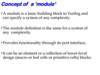
Concept of a‘module’
•A module is a basic building block in Verilog and
can specify a system of any complexity.
•The module definition is the same for a system of
any complexity.
•Provides functionality through its port interface.
•It can be an element or a collection of lower-level
design (macro or leaf cells or primitive cells) blocks.
How to declarea module ?
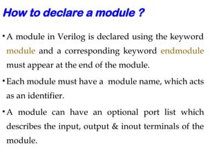
•A module in Verilog is declared using the keyword
module and a corresponding keyword endmodule
must appear at the end of the module.
•Each module must have a module name, which acts
as an identifier.
•A module can have an optional port list which
describes the input, output & inout terminals of the
module.
4.
Module declaration -Examples
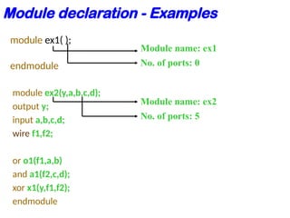
module ex1( );
endmodule
module ex2(y,a,b,c,d);
output y;
input a,b,c,d;
wire f1,f2;
or o1(f1,a,b)
and a1(f2,c,d);
xor x1(y,f1,f2);
endmodule
Module name: ex1
No. of ports: 0
Module name: ex2
No. of ports: 5
5.
Nesting of modules
•In Verilog nesting of modules is not permitted i.e., one
module definition cannot contain another module definition
within the module and endmodule statements.
module counter(q, clk, reset);
output [3:0]q;
input clk, reset;
module T_FF(q, clock, reset) // Illegal
endmodule
endmodule
6.
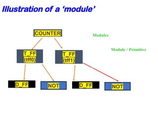
Illustration of a‘module’
COUNTER
T_FF
(tff0)
T_FF
(tff1)
D_FF NOT D_FF NOT
Modules
Module / Primitive
7.
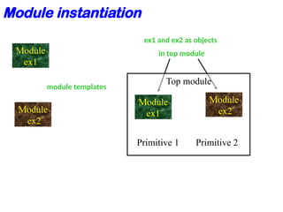
Module instances
•A moduleprovides a template from which one can
create actual objects.
•Each object has its own name, variables, parameters
and I/O interface.
•The process of creating objects from a module
template is called instantiation, and the objects are
called instances.
•Primitives and modules can be instantiated.
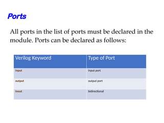
Ports
All ports inthe list of ports must be declared in the
module. Ports can be declared as follows:
Verilog Keyword Type of Port
input input port
output output port
inout bidirectional
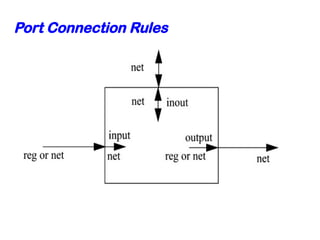
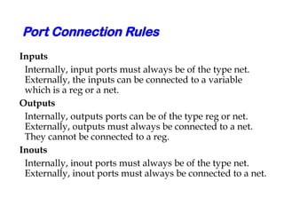
Port Connection Rules
Inputs
Internally,input ports must always be of the type net.
Externally, the inputs can be connected to a variable
which is a reg or a net.
Outputs
Internally, outputs ports can be of the type reg or net.
Externally, outputs must always be connected to a net.
They cannot be connected to a reg.
Inouts
Internally, inout ports must always be of the type net.
Externally, inout ports must always be connected to a net.
15.
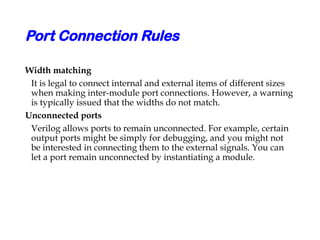
Port Connection Rules
Widthmatching
It is legal to connect internal and external items of different sizes
when making inter-module port connections. However, a warning
is typically issued that the widths do not match.
Unconnected ports
Verilog allows ports to remain unconnected. For example, certain
output ports might be simply for debugging, and you might not
be interested in connecting them to the external signals. You can
let a port remain unconnected by instantiating a module.
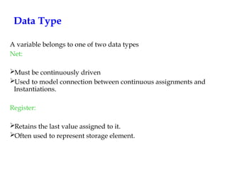
Data Type
A variablebelongs to one of two data types
Net:
Must be continuously driven
Used to model connection between continuous assignments and
Instantiations.
Register:
Retains the last value assigned to it.
Often used to represent storage element.
19.
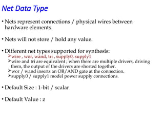
Net Data Type
•Nets represent connections / physical wires between
hardware elements.
• Nets will not store / hold any value.
• Different net types supported for synthesis:
wire , wor, wand, tri , supply0, supply1
wire and tri are equivalent ; when there are multiple drivers, driving
them, the output of the drivers are shorted together.
wor / wand inserts an OR/AND gate at the connection.
supply0 / supply1 model power supply connections.
• Default Size : 1-bit / scalar
• Default Value : z
20.
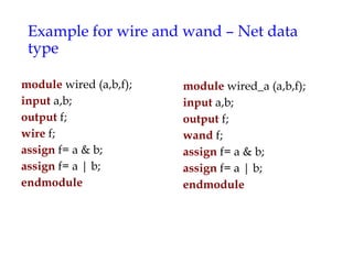
Example for wireand wand – Net data
type
module wired (a,b,f);
input a,b;
output f;
wire f;
assign f= a & b;
assign f= a | b;
endmodule
module wired_a (a,b,f);
input a,b;
output f;
wand f;
assign f= a & b;
assign f= a | b;
endmodule
21.
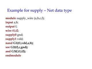
Example for supply– Net data type
module supply_wire (a,b,c,f);
input a,b;
output f;
wire t1,t2;
supply0 gnd;
supply1 vdd;
nand G1(t1,vdd,a,b);
xor G2(t2,c,gnd);
and G3(f,t1,t2);
endmodule
22.
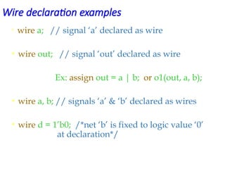
Wire declaration examples
•wire a; // signal ‘a’ declared as wire
• wire out; // signal ‘out’ declared as wire
Ex: assign out = a | b; or o1(out, a, b);
• wire a, b; // signals ‘a’ & ‘b’ declared as wires
• wire d = 1’b0; /*net ‘b’ is fixed to logic value ‘0’
at declaration*/
23.
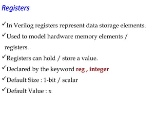
Registers
In Verilog registersrepresent data storage elements.
Used to model hardware memory elements /
registers.
Registers can hold / store a value.
Declared by the keyword reg , integer
Default Size : 1-bit / scalar
Default Value : x
24.
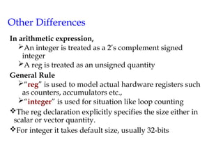
Other Differences
In arithmeticexpression,
An integer is treated as a 2’s complement signed
integer
A reg is treated as an unsigned quantity
General Rule
“reg” is used to model actual hardware registers such
as counters, accumulators etc.,
“integer” is used for situation like loop counting
The reg declaration explicitly specifies the size either in
scalar or vector quantity.
For integer it takes default size, usually 32-bits
25.
Vectors
• Nets orregister data types can be declared as
vectors (more no. of bits).
•If bit width is not specified then the default value
is 1-bit (scalar).
wire a; // default scalar net value
wire [7:0] bus; // 8-bit bus
wire [31:0] busA, busB, busC; //32- bit bus
reg clock; // scalar register(default)
reg [0:40] virtual_addr; //virtual address 41 bits
26.
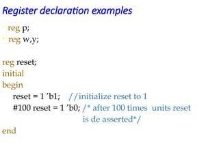
Register declaration examples
•reg p;
• reg w,y;
reg reset;
initial
begin
reset = 1 ’b1; //initialize reset to 1
#100 reset = 1 ’b0; /* after 100 times units reset
is de asserted*/
end
27.
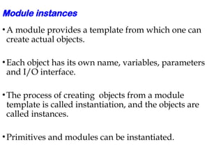
Addressing Vectors
• wire[15:0]busA;
busA[9]; // bit # 9 or 10th bit of vector busA from LSB
• wire [0:15]busB;
busB[9]; // bit # 9 or 7th bit of vector busB from LSB
• reg [31:0]cnt_out;
cnt_out[14:7]; // group of 8 bits of a vector register
cnt_out[7:14]; // is illegal addressing
#1 Regardless of its complexity, module specification(module definition) has the same structure.
Primitive cells or leaf cells are those cells which are readily available form the HDL library. That means the functions are readily available and can be made use of, by the user without writing the module definition.
But for the user defined functions it is mandatory that he uses the module definition, which is the same for any design complexity.
#3 The module & endmodule structure(module definition) is not required for primitive cells.
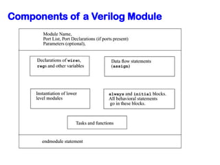
Between the two keywords module and endmodule there are three elements:
Interface: consisting of port and parameter declarations.
Body: specification of internal part of the module.
Optimal add-ons: specified anywhere in the module with the `include compiler directive.
An identifier should not be a reserved keyword, that means reserved keywords cannot be used as identifiers.
#4 A module communicates with the other modules or the external environment through its ports. So the functionality of any module is reflected through its ports by hiding the internals of the module, which describes the functionality for that module.
If any module doesn’t have the port list, then it can’t communicate with the rest of the design blocks or with the external environment.
#5 As shown above the nesting of modules is not permitted in verilog. Instead we can make use of the modules by instantiating them.
In the above example, we can instantiate the T_FF module as shown: T_FF t1(q, clock, reset);
#6 The module can be a single element or a group other elements(elements can be the primitive or leaf cells or even the other user defined modules).
In the above example the module which describes the counter is realized with the help of other sub-blocks as shown. The sub-blocks can be user defined blocks such as T_FF and D_FF, or may be the primitive or leaf cells such as NOT. In this context we can say that a module can be a group of elements.
Since the D_FF module doesn’t use any sub-blocks or leaf cells, we can say that the module can be even a single element.
#7 In verilog nesting of modules is illegal. That is one module definition cannot contain another module definition within the module and endmodule statements. But one module definition can contain one or more instances of other modules. The instantiated modules reflect their functionality through their ports in the module which had instantiated them.
Every module instance should have its instance name. But for primitive instantiation the instance name is optional. Even it is recommended that the primitive instantiation should have the instance name, so that multiple instances of the same primitive can be identified by their instance name.
#8 In the above example, the module 1 and module 2 functionality had to described at first, with the help of module definitions. there after if we want to make use of them in other module then they have to be instantiated in the corresponding module(here it is main module.
But writing the module definitions of module 1 and module 2 inside the main module definition is not allowed in verilog.
#19 The nets should have the values continuously driven on them, otherwise by default they go to high impedance state(z). Unless and until a net is driven by some driver it takes the value of z.
#23 Unless a value is written in to register it holds a ‘x’ value by default in it.
Once a value is inside the register, the value doesn’t change unless another value is written in to it(i.e. the reg data types have the capability to store the values).
The other register data types are integer, real, time register.
![Nesting of modules
• In Verilog nesting of modules is not permitted i.e., one
module definition cannot contain another module definition
within the module and endmodule statements.
module counter(q, clk, reset);
output [3:0]q;
input clk, reset;
module T_FF(q, clock, reset) // Illegal
endmodule
endmodule](https://image.slidesharecdn.com/lecture-2-250710172844-e1f4e113/85/Concept-of-a-module-in-verilog-coding-5-320.jpg)
![Port Declarations
module fulladd4(sum, c_out, a, b, c_in);
//Begin port declarations section
output [3:0] sum;
output c_cout;
input [3:0] a, b;
input c_in; //End port declarations section ...
<module internals> ...
endmodule](https://image.slidesharecdn.com/lecture-2-250710172844-e1f4e113/85/Concept-of-a-module-in-verilog-coding-12-320.jpg)

![Vectors
• Nets or register data types can be declared as
vectors (more no. of bits).
•If bit width is not specified then the default value
is 1-bit (scalar).
wire a; // default scalar net value
wire [7:0] bus; // 8-bit bus
wire [31:0] busA, busB, busC; //32- bit bus
reg clock; // scalar register(default)
reg [0:40] virtual_addr; //virtual address 41 bits](https://image.slidesharecdn.com/lecture-2-250710172844-e1f4e113/85/Concept-of-a-module-in-verilog-coding-25-320.jpg)
![Addressing Vectors
• wire [15:0]busA;
busA[9]; // bit # 9 or 10th bit of vector busA from LSB
• wire [0:15]busB;
busB[9]; // bit # 9 or 7th bit of vector busB from LSB
• reg [31:0]cnt_out;
cnt_out[14:7]; // group of 8 bits of a vector register
cnt_out[7:14]; // is illegal addressing](https://image.slidesharecdn.com/lecture-2-250710172844-e1f4e113/85/Concept-of-a-module-in-verilog-coding-27-320.jpg)