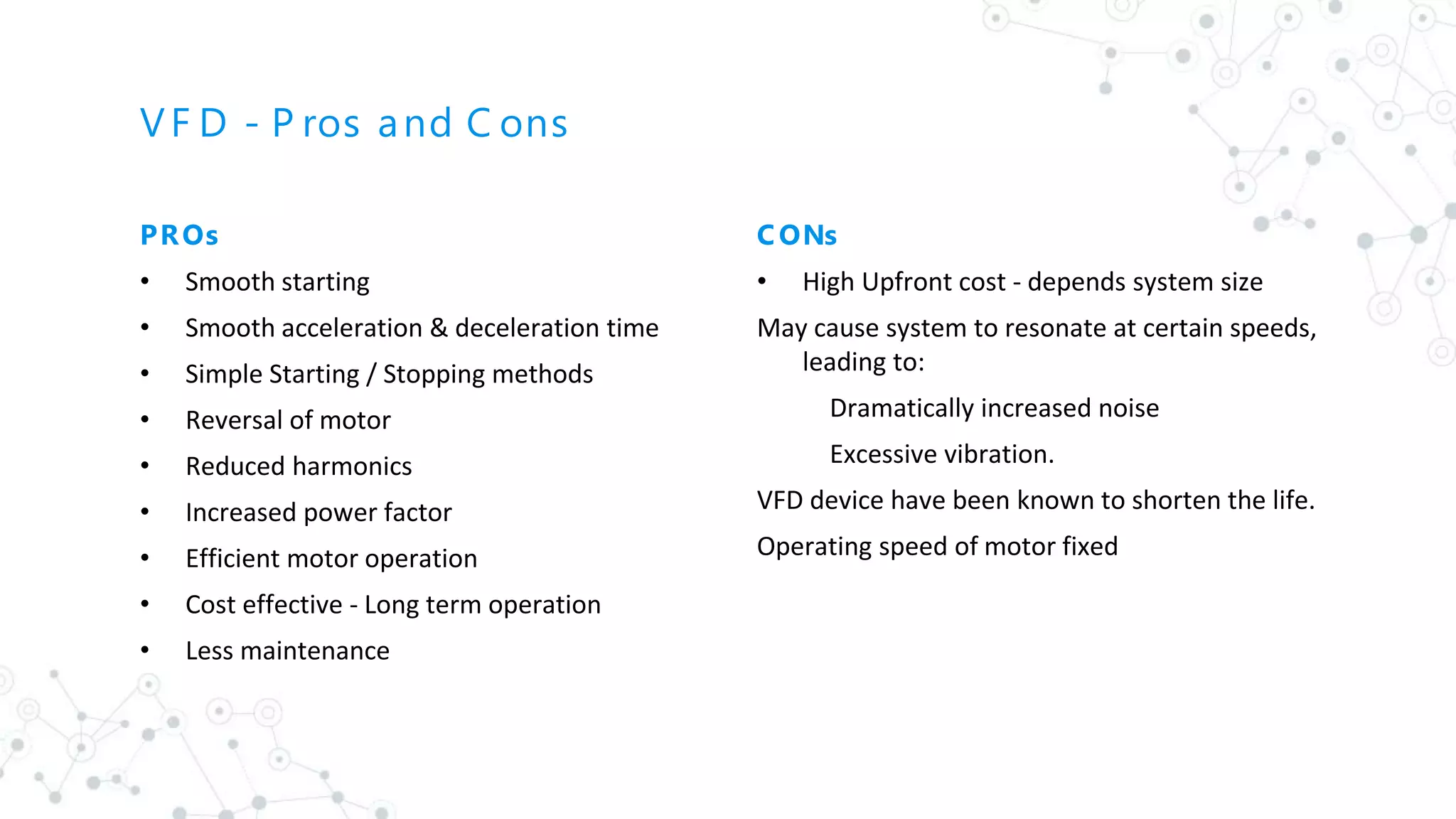
A Variable Frequency Drive (VFD) is an adjustable-speed drive that controls AC motor speed and torque by varying input frequency and voltage. It offers advantages such as controlled acceleration, energy savings, and reduced maintenance costs but may have high upfront costs and can cause resonance issues. Proper selection involves considering factors like operating voltage, horsepower rating, and enclosure type.

![What Is a VF D?
[1 ]
◎ A type of adjustable-speed drive
◎ Vary motor input frequency and voltage <=> C ontrol AC
motor output speed & torque
◎ Part of “electro-mechanical” drive systems
2
https://en.wikipedia.org/wiki/Variable -frequency_ drive [1 ]
Also known as
Adjustable
Frequency
Drive (AFD)
Variable -
Voltage
/Variable
- Frequency
(VVVFD)
Variable
S peed Drive
(VSD)
AC Drive
Micro Drive
Inverter Drive](https://image.slidesharecdn.com/vfd-200824064530/75/Variable-Frequency-Drives-2-2048.jpg)
![Need
[2]
C ontrolled S tarting
C urrent
Reduced Power Line
Disturbances
Lower Power Demand
on S tart
Adjustable Operating
S peed
Adjustable Torque
Limit
3
S peed C ontrol Is one of the primary advantages of switching to VF Ds. VF Ds allow motor speeds
to be ramped up and ramped down ensuring connected load is aintained at the required speeds with
necessary energy utilization.
C ontrolled
Acceleration
C ontrolled S topping E nergy S avings Reverse Operation
E liminates Use of
Mech. Drive
C omponents https://www.wolfautomation.com/blog/benefits -vfd/ [2]
https://www.paddockindustries.com/wp-content/uploads/201 7/05/Why-Variable-F requency-Drive-F inal-2-1 6-
1 1 .pdf[3]
Lower Maintenance
C osts
[3]
Longer Motor Life
[3]](https://image.slidesharecdn.com/vfd-200824064530/75/Variable-Frequency-Drives-3-2048.jpg)
![What Is a VF D? - S chematic & Internal C onstruction[4]
4
https://www.youtube.com/watch? reload=9&v=3-cs 4eE iB Wo [4]](https://image.slidesharecdn.com/vfd-200824064530/75/Variable-Frequency-Drives-4-2048.jpg)
![What Is a VF D? - S chematic & Internal C onstruction[4]
5](https://image.slidesharecdn.com/vfd-200824064530/75/Variable-Frequency-Drives-5-2048.jpg)
![Motor S tarter C ircuit - Direct-On-L ine (DOL )
6
[5]](https://image.slidesharecdn.com/vfd-200824064530/75/Variable-Frequency-Drives-6-2048.jpg)
![Motor S tarter C ircuit - S tar Delta
7
[6]](https://image.slidesharecdn.com/vfd-200824064530/75/Variable-Frequency-Drives-7-2048.jpg)
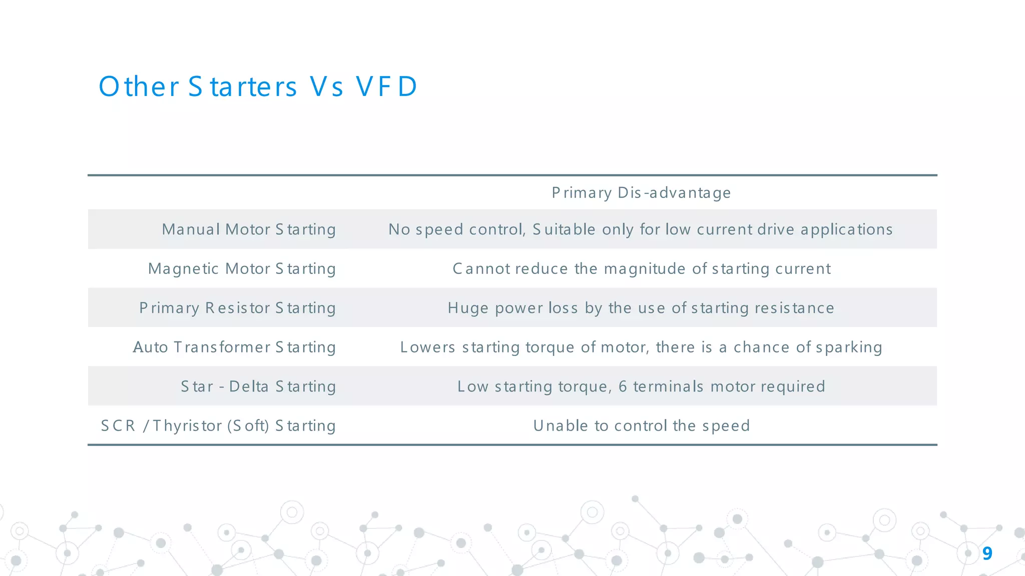
![Manual Motor S tarting
Other S tarters [4]
8
Magnetic Motor S tarting
Primary Resistor S tarting
Auto Transformer S tarting
S C R S tarting /S oft S tarting
https://www.youtube.com/watch? reload=9&v=3-cs 4eE iB Wo [4]](https://image.slidesharecdn.com/vfd-200824064530/75/Variable-Frequency-Drives-8-2048.jpg)


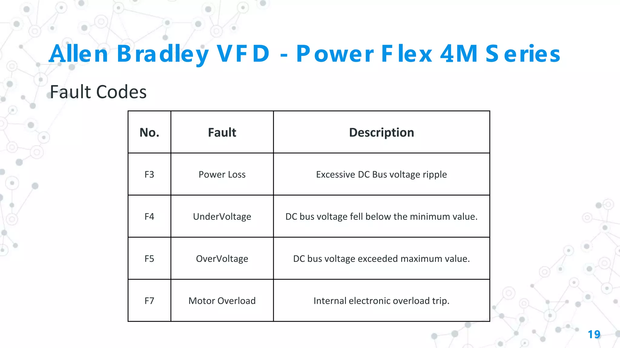
![Allen Bradley VF D - Power F lex 4M S eries
Parameter Configuration
18
No. Parameter
Min / Max
Value
Display/Options
Default
Value
P101 [Motor Nameplate Volts]
20 to Drive
Rated Volts
1 VAC
Based on
Drive Rating
P102 [Motor Nameplate Hertz] 10 to 400 Hz 1 Hz 60 Hz
P103 [Motor Overload Current]
0.0 to (Drive
Rated Amps x2)
0.1 Amps
Based on
Drive Rating
P104 [Minimum Frequency] 0.0 to 400 Hz 0.1 Hz 0.0 Hz
P105 [Maximum Frequency] 0.0 to 400 Hz 1 Hz 60 Hz
P106 [Start Source] 0 to 5
Keypad, 3 Wire, 2 Wire, 2 Wire
Level Sensor, 2 Wire High
Speed, Communication Port
0
P107 [Stop Mode] 0 to 7
Ramp, Coast, DC Brake, DC
Brake Auto
0
P108 [Speed Reference] 0 to 5
Drive Potentiometer, Internal
Frequency, 0-10V input, 4-
20mA input, Preset Frequency,
Communication Port
0
P109 [Acceleration time 1] 0.0 to 600 Secs 0.1 Secs 10.0 Secs
P110 [Deceleration time 1] 0.0 to 600 Secs 0.1 Secs 10.0 Secs
P111
[Motor Overload
Retention]
0 or 1 0 = Disabled 1= Enabled 0
P112 [Reset To Defaults] 0 or 1 0 = Idle State 1 = Reset Defaults 0
No. Parameter Min/max Value Display/Options
Default
Value
D001
The Output Frequency
Present at T1,T2 & T3.
0.0 to (P105)
Maximum Freq
0.1 Hz Read Only
D003
The Output Current present
at T1,T2 & T3.
0.0 to (Drive
Rated Amps x2)
0.01 Amps Read Only
D004
Output voltage present at
terminals T1, T2 & T3
0 to Drive Rated
Volts
0.1 VAC Read Only
D020
The present value of the
voltage at I/O Terminal 13
(100.0% = 10 volts).
0.0 to 100.0% 0.1% Read Only
D022
Present operating
temperature of the drive
power section.
0 to 120 degC 1 degC Read Only
No. Parameter Min/max Value Display/Options
Default
Value
T212
Sets analog input level
corresponding to P105 - if a
0-10V input is used by P108
0.0 to 100.0% 0.1% 100.0%
T221
Sets condition that changes
state of o/p relay contacts.
0 to 13 0 = Ready/Fault 0
No. Parameter Min/max Value Display/Options
Default
Value
A434
A442](https://image.slidesharecdn.com/vfd-200824064530/75/Variable-Frequency-Drives-18-2048.jpg)


![PLC Ladder Programming [Mechatronics]](https://cdn.slidesharecdn.com/ss_thumbnails/plc-ppt-snteli-200503070616-thumbnail.jpg?width=640&height=640&fit=bounds)


