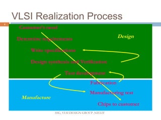
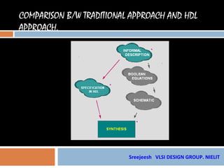
Hardware description languages (HDLs) like VHDL and Verilog allow designers to model digital circuits and systems. HDLs enable increased productivity through design reuse, faster design changes, and exploration of alternative architectures. VHDL is a popular, industry standard HDL that supports modeling designs hierarchically at different levels of abstraction from behavioral to structural. VHDL models can be simulated and synthesized, facilitating early verification of a design's functionality before implementation.
VHDL is defined by IEEE. This standard is known by all the VHDL tool developers. So
there is only one language to learn. This language is used by all the circuit designers around the world. The life time for this language is assured, since it is an IEEE standards. Any investment or learning is assured for lifetime. Abundance of models available from different sources can be used with ease. Some tools might support Foreign Language Interface, by which you can add your model in C language to the VHDL code. It is a modern language, powerful and general. Other advantages include readability of the code and portability. The code developed is portable to any technology at any time. Time to market is short (leads to leadership in the market). Any error found during the simulation phase is less expensive than by discovering the errors after making the circuit board (Investment is saved). The great advantage is that the Project Managers can modify the specification without leading to disaster (only the necessary portion of the code need to be changed). It can deliver designs 100% error free at short duration. New Concepts in
hardware design (for example, in image processing, DSP, etc.,) can be modeled in VHDL and its efficiency or viability can be proven without doing the hardware. A large number of ASICs fail to work when plugged into a system even if they meet their specifications first time. VHDL addresses this issue in two ways: A VHDL specification can be executed in order to achieve a high level of confidence in its correctness before commencing design, and may simulate one to two orders of magnitude faster than a gate level description. A VHDL specification for a part can form the basis for a simulation model to verify the operation of the part in the wider system context (e.g. printed circuit board simulation). This depends on how accurately the specification handles aspects such as timing and initialization.
please explain tooSolutionVHDL (Very High Speed IC Hardware descriptio.docxceveline2
please explain too
Solution
VHDL (Very High Speed IC Hardware description Language) is one of the standard hardware description language used to design digital systems. VHDL can be used to design the lowest level (gate level) of a digital system to the highest level (VLSI module). VHDL though being a rigid language with a standard set of rules allows the designer to use different methods of design giving different perspectives to the digital system. Other than VHDL there are many hardware description languages available in the market for the digital designers such as Verilog, ABEL, PALASM, CUPL, and etc but VHDL and Verilog are the most widely used HDLs. The major difference between hardware description programming languages and others is the integration of time. Timing specifications are used to incorporate propagation delays present in the system
.
Study and Comparison of Open Source and Licensed VLSI CAD Tools using CMOS De...ijsrd.com
the design of VLSI circuits can be achieved at many different refinement levels from the most detailed layout to the most abstract architectures. VLSI design has been the study of electronic design automation and related semiconductor science, and many software tools have been written to solve one or more problems associated with the VLSI design flow. VLSI CAD tools have emerged as a boon in assisting VLSI Design engineers to choose and optimize various design models and technology. The importance of CAD tool can be understood by seeing its complex algorithms, data structures and modeling assumptions used in each of the following steps namely logic synthesis, logic verification, layout synthesis, timing verification and many others. Thus a number of standard tools have emerged to design and analyze VLSI chip from one step of the flow to another. Computer-aided design (CAD) is the use of computer systems to assist in the creation, modification, analysis, or optimization of a design. Computer aids in VLSI now offer advance capabilities so engineers can better visualize their product designs. The VLSI CAD tools work sideways together with chip designers to design and analyze entire semiconductor chips. In this paper, a number of open-source and licensed CAD tools will be studied and compared. The tools have been used for various commercial and academic purposes in various companies and universities at different design abstraction levels. This paper will help to comprehend many EDA tools and help to select appropriate computer aid for chip design.
This Presentation covers most of VHDL designing basic from scratch.
click the below link for contents
http://eutectics.blogspot.com/2014/01/how-to-design-programs-using-vhdl-all.html
Interoperability of Reconfiguring System on FPGA Using a Design Entry of Hard...IDES Editor
For a long ago, world of digital design has spread
out in the many major and a lot of logics, approaches, and
theories has been proposed. The digital emerges as a solution
of a daily-life need and applicable on such technology from
the developing devices until software-based. All of the designs
has a significant point on the spesification, integration, and
optimization. The designers have been trying to make a good
designs on both hardware and software, latest both
combinations have been known as the basic idea of hardware/
software co-design. The state-of-the art computer is very
interesting to research because of its implementation can
make changes of the cycle of reconfigurable objects. This paper
presents a comparison of the two role plays in reconfigurable
devices especially FPGA-based, i.e. Altera and Xilinx. The
idea is that of a simple compiler has a good performance designs
for synthesizing Very high speed integrated circuit Hardware
Description Language (VHDL) code as well as the other
complexity software that more powerful. So, this paper
proposes such method as interoperability for reconfiguring
devices to get the point why few of the standard VHDL code
can’t be synthesised in the different compiler of VHDL code
between Xilinx and Altera. The project of compiler softwares
that is observed from Xilinx is ISE and from Altera is Max+Plus
II. Max+Plus II is a low-cost software than ISE Xilinx, although
both Xilinx and Altera devices have a different structure each
other.
This course for someone with no previous experience with VHDL to learn VHDL language and write codes targeting hardware.
This course is focusing on syntax of VHDL, basic design circuits.
For all course videos and material visit YouTube channel
www.youtube.com/channel/UCcecv3gqLQCRT8MS3_aRn9Q
3. Course Contents
What are HDLs ?
Are they really required ?.
VHDL
Verilog
Advantages/Disadvantages
4. VLSI Realization Process
4
Customer’s need
Determine requirements Design
Write specifications
Design synthesis and Verification
Test development
Fabrication
Manufacturing test
Manufacture
Chips to customer
SSG, VLSI DESIGN GROUP ,NIELIT
5. Hardware Description Language
HDL is any language from a class of computer
languages and/or programming languages for
formal description of electronic circuits. It can
describe the circuit's operation, its design and
organization, and tests to verify its operation
by means of simulation.
HDLs are used to write executable specifications
of some piece of hardware.
Sreejeesh VLSI DESIGN GROUP. NIELIT
6. HDLs - Motivation
Increased productivity
shorter development cycles, more features,
but........still shorter time-to-market, 10-20K
gates/day/engineer
Flexible modeling capabilities.
can represent designs of gates or systems
description can be very abstract or very
structural
Sreejeesh VLSI DESIGN GROUP. NIELIT
7. Design reuse is enabled.
packages, libraries, support reusable, portable
code
Design changes are fast and easily done
convert a 8-bit register to 64-bits........four key
strokes, and its done!
exploration of alternative architectures can be
done quickly
Sreejeesh VLSI DESIGN GROUP. NIELIT
8. Use of various design methodologies.
top-down, bottom-up, complexity hiding
(abstraction)
Technology and vendor independence.
same code can be targeted to CMOS, ECL,
GaAs
same code for: TI, NEC, LSI, TMSC
same code for: .5um, .35um, .25um, .18um
Sreejeesh VLSI DESIGN GROUP. NIELIT
9. Enables use of logic synthesis which allows a
investigation of the area and timing space.
Using a standard language promotes clear
communication of ideas and designs.
Sreejeesh VLSI DESIGN GROUP. NIELIT
10. DO WE REALLY NEED HDL’S ??
Before Emergence of HDL’s
How was Designing Field ??
We where designing systems
using Boolean equations…isn't ?
12. DRAWBACKS OF TRADITIONAL
DESIGNING METHODS
System will be specified as interconnected blocks and this
is not how specification of system is given to you or
created.
System spec is always given as behavior of a system.
Handling of large complex system is not feasible.
Analyzing thousands of Boolean equations is not possible.
We all know that over six thousand gates the schematic
become incomprehensible.
We in modern world deal with millions of gates.
Sreejeesh VLSI DESIGN GROUP. NIELIT
13. So We go for HDL’s …
What are these HDL’s ??
“ H ardware D escription L anguage”.
What they do ??
Describe digital circuits.
HDLs allowed the designers to model the concurrency of
processes found in hardware elements.
HDLs such as Verilog HDL and VHDL became popular.
Sreejeesh VLSI DESIGN GROUP. NIELIT
17. ORIGIN OF VHDL
Initiated by US Government’s Dept of Defense VHSIC
•
Program in 1980.
IBM, TI and Intermetrics started the development of VHDL in
•
1983
VHDL Ver. 7.2 released in 1985.
•
IEEE standard 1076-1987 in 1987.
•
IEEE 1076-1993 - revision in 1993
•
Sreejeesh VLSI DESIGN GROUP. NIELIT
18. V HDL
Very High Speed Integrated Circuit Hardware
Description Language
VHDL is an industry standard HDL for the Description, Modeling and
Synthesis of digital circuits and systems.
Sreejeesh VLSI DESIGN GROUP. NIELIT
19. V HDL
It is the most popular HDL , worldwide.
System specification can be done structural or/and in behavioral levels.
Good VHDL simulation tools are available in market at reasonable price.
Synthesis with VHDL is available with all most all EDA vendors .
It is a universal modeling language, i.e. it can be used to model electromechanical
systems, hydraulics, chemical and other system. It is not restricted only to
electronics.
20. BASICFEATURES OF VHDL
CONCURRENCY.
SUPPORTS SEQUENTIAL STATEMENTS.
SUPPORTS FOR TEST & SIMULATION.
STRONGLY TYPED LANGUAGE.
SUPPORTS HIERARCHIES.
SUPPORTS FOR VENDOR DEFINED
LIBRARIES.
SUPPORTS MULTIVALUED LOGIC.
Sreejeesh VLSI DESIGN GROUP. NIELIT
21. CONCURRENCY
VHDL is a concurrent language.
HDL differs with Software languages with respect
to Concurrency only.
VHDL executes statements at the same time in
parallel, as in Hardware.
Sreejeesh VLSI DESIGN GROUP. NIELIT
23. DESIGN PROCESS OF A DIGITAL SYSTEM
Design process of a digital system has 4
phases
- Requirement Analysis &
Specification.
- Design .
- Implementation & Testing.
- Manufacturing .
In 1st phase, Function, Performance and
interface requirements are determined and
specified.
Sreejeesh VLSI DESIGN GROUP. NIELIT
24. DESIGN PROCESS OF A DIGITAL SYSTEM..
In 2nd phase , system is partitioned into different levels of
decomposition such as
- System Design : System is decomposed several
subsystems and the communication protocol among them is also
defined.
- Architectural Design : Architectural style and performance of
each subsystem is determined.
25. DESIGN PROCESS OF A DIGITAL SYSTEM…
RTL Design : Architecture is translated into an interconnection of RTL Modules.
- Logic design: RTL Modules are constructed using logic
gates.
In 3rd phase, subsystems are implemented and tested including partitioning,
placement and routing to produce a layout of circuit.
In final phase , process is to prototype , manufacture the design.
26.
27. ADVANTAGES OF VHDL
Can verify design functionality early in the design process and
simulate a design written as a VH description.
DL
Logic Synthesis and optimization converts a VH description
DL
to a gate level implementation in a given technology.
Reduces circuit design time and errors.
VHDL descriptions provide technology independent
documentation for a design and its functionality.
28. ADVANTAGES OF VHDL..
Powerful constructs to write complex logic.
It has multiples levels of design descriptions.
It supports design libraries and the creation of reusable
components.
It provides for design hierarchies to create module design.
29. ADVANTAGES OF VHDL….
Device independent design
VHDL permits to create a design without first choosing
the device for implementation
Portability
VHDL is an IEEE standard.
Libraries of VHDL models of components can be
shared across platforms, tools organization and
technical group
ASIC Migration
Quick time to market and low cost
30. CAPABILITIES
VHDL supports design hierarchies
A digital system can be modeled as a set of
interconnected components
It supports flexible design methodologies
Top-down , Bottom-up or mixed.
VHDL is not technology specific.
It can support various hardware technologies
It supports both synchronous and asynchronous timing
models
NIELIT
31. CAPABILITIES…
Various modeling techniques such as FSM, algorithmic and Boolean
equations can be modeled using VHDL.
Any large design can be modeled using VHDL
No limitation imposed by the size of a design
Test benches can be written in VHDL to test other models.
Sreejeesh VLSI DESIGN GROUP.
NIELIT
32. CAPABILITIES…
Propagation delays, set-up and hold time timing constraints can be described
in VHDL
Generics and attributes are useful in describing parameterized design
Models written in VHDL can be verified by Simulation
Behavioral models are capable of being synthesized to gate- level description
Sreejeesh VLSI DESIGN GROUP.
NIELIT
34. DISADVANTAGES
Less control of defining gate level implementation.
The implementation created by synthesis tool is
inefficient.
The quality of synthesis varies from tool to tool.
35. SUMMARY
VHDL modeling can be used to model
hardware at multiples levels of abstraction.
VHDL is independent of technology and
design methodologies and promotes portable
descriptions, rapid prototyping and free
exchange of models among organizations and
individuals.