Balancing of reciprocating masses
•Download as PPTX, PDF•
46 likes•34,022 views

The various forces acts on the reciprocating parts of an engine. The resultant of all the forces acting on the body of the engine due to inertia forces only is known as unbalanced force or shaking force.

Recommended
More Related Content
What's hot
What's hot (20)
Similar to Balancing of reciprocating masses
Similar to Balancing of reciprocating masses (20)
More from ANKIT SAXENA Asst. Prof. @ Dr. Akhilesh Das Gupta Institute of Technology and Management, New Delhi
More from ANKIT SAXENA Asst. Prof. @ Dr. Akhilesh Das Gupta Institute of Technology and Management, New Delhi (17)
Recently uploaded
Recently uploaded (20)
Balancing of reciprocating masses
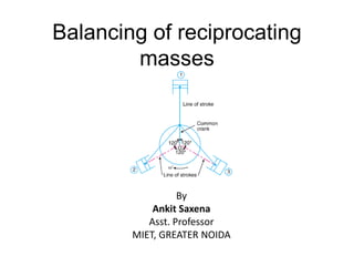
- 1. Balancing of reciprocating masses By Ankit Saxena Asst. Professor MIET, GREATER NOIDA
- 2. Introduction• The various forces acts on the reciprocating parts of an engine. • The resultant of all the forces acting on the body of the engine due to inertia forces only is known as unbalanced force or shaking force. Let FR = Force required to accelerate the reciprocating parts, FI =Inertia force due reciprocating parts, FN=Force on the sides of the cylinder walls or normal force acting on the cross-head guides, and FB=Force acting on the crankshaft bearing or main bearing.
- 3. • Since FR and FI are equal in magnitude but opposite in direction, therefore they balance each other. • The horizontal component of FB (i.e. FBH) acting along the line of reciprocation is also equal and opposite to FI. • This force FBH = FU is an unbalanced force or shaking force and required to be properly balanced. • The effect of the reciprocating parts is to produce a shaking force and a shaking couple. • Since the shaking force and a shaking couple vary in magnitude and direction during the engine cycle, therefore they cause very objectionable vibrations.
- 4. Primary and Secondary Unbalanced Forces of Reciprocating Masses Let m = Mass of the reciprocating parts, l = Length of the connecting rod PC, r = Radius of the crank OC, θ = Angle of inclination of the crank with the line of stroke PO, ω = Angular speed of the crank, n = Ratio of length of the connecting rod to the crank radius = l / r. Acceleration of the reciprocating parts ∴ Inertia force due to reciprocating parts or force required to accelerate the reciprocating parts, FI = FR = Mass × acceleration = 2 Cos 2 CosRa r n 2 Cos 2 CosRma m r n
- 5. The horizontal component of the force exerted on the crank shaft bearing (i.e. FBH) is equal and opposite to inertia force (FI). This force is an unbalanced one and is denoted by FU. ∴ Unbalanced force, FU= FP+FS • The expression is known as primary unbalanced force and is called Secondary unbalanced force. 2 Cos 2 CosUF m r n 2 2 Cos2 Cosm r m r n 2 Cosm r 2 Cos 2 m r n
- 7. Partial Balancing of Unbalanced Primary Force in a Reciprocating Engine The primary force acts from O to P along the line of stroke. Hence, balancing of primary force is considered as equivalent to the balancing of mass m rotating at the crank radius r. This is balanced by having a mass B at a radius b, placed diametrically opposite to the crank pin C. The primary unbalanced force may be considered as the component of the centrifugal force produced by a rotating mass m placed at the crank radius r.
- 8. The centrifugal force produced due to the revolving mass B, has also a vertical component (perpendicular to the line of stroke) of magnitude This force remains unbalanced. The maximum value of this force is equal to when is 90° and 270°, which is same as the maximum value of the primary force. 2 inB rs 2 B b 2 m r From the above discussion, we see that in the first case, the primary unbalanced force acts along the line of stroke whereas in the second case, the unbalanced force acts along the perpendicular to the line of stroke. The maximum value of the force remains same in both the cases. It is thus obvious, that the effect of the above method of balancing is to change the direction of the maximum unbalanced force from the line of stroke to the perpendicular of line of stroke. As a compromise let a fraction ‘c’ of the reciprocating masses is balanced, such that
- 9. ∴ Unbalanced force along the line of stroke
- 11. Effect of Partial Balancing of Reciprocating Parts of Two Cylinder Locomotives The effect of an unbalanced primary force along the line of stroke is to produce; 1. Variation in tractive force along the line of stroke 2. Swaying couple. 3. Hammer blow 1. Variation of Tractive Force The resultant unbalanced force due to the two cylinders, along the line of stroke, is known as tractive force, Let the crank for the first cylinder be inclined at an angle θ with the line of stroke Since the crank for the second cylinder is at right angle to the first crank, therefore the angle of inclination for the second crank will be (90° + θ ).
- 13. 2. Swaying Couple The unbalanced forces along the line of stroke for the two cylinders constitute a couple about the centre line YY between the cylinders This couple has swaying effect about a vertical axis, and tends to sway the engine alternately in clockwise and anticlockwise directions. Hence the couple is known as swaying couple. Let a = Distance between the centre lines of the two cylinders. ∴ Swaying couple The swaying couple is maximum or minimum when (cosθ + sin θ) is maximum or minimum. For (cosθ + sin θ) to be maximum or minimum,
- 15. 3. Hammer Blow The maximum magnitude of the unbalanced force along the perpendicular to the line of stroke is known as hammer blow. We know that the unbalanced force along the perpendicular to the line of stroke due to the balancing mass B, at a radius b, in order to balance reciprocating parts only is .This force will be maximum when sin θ is unity, i.e. when = 90° or 270°.2 sinB b
- 16. Numerical An inside cylinder locomotive has its cylinder centre lines 0.7 m apart and has a stroke of 0.6 m. The rotating masses per cylinder are equivalent to 150 kg at the crank pin, and the reciprocating masses per cylinder to 180 kg. The wheel centre lines are 1.5 m apart. The cranks are at right angles. The whole of the rotating and 2/3 of the reciprocating masses are to be balanced by masses placed at a radius of 0.6 m. Find the magnitude and direction of the balancing masses. Find the fluctuation in rail pressure under one wheel, variation of tractive effort and the magnitude of swaying couple at a crank speed of 300 r.p.m.
- 22. Balancing of Radial Engines (Direct and Reverse Cranks Method ) The method of direct and reverse cranks is used in balancing of radial or V-engines, in which the connecting rods are connected to a common crank. Since the plane of rotation of the various cranks (in radial or V-engines) is same, therefore there is no unbalanced primary or secondary couple. Consider a reciprocating engine mechanism as shown Let the crank OC (known as the direct crank) rotates uniformly at ω radians per second in a clockwise direction. Let at any instant the crank makes an angle θ with the line of stroke OP. The indirect or reverse crank OC′ is the image of the direct crank OC, when seen through the mirror placed at the line of stroke. A little consideration will show that when the direct crank revolves in a clockwise direction, the reverse crank will revolve in the anticlockwise direction. We shall now discuss the primary and secondary forces due to the mass (m) of the reciprocating parts at P.
- 23. 1. Considering the primary forces • Let us suppose that the mass (m) of the reciprocating parts is divided into two parts, each equal to m / 2. • It is assumed that m / 2 is fixed at the direct crank (termed as primary direct crank) pin C and m / 2 at the reverse crank (termed as primary reverse crank) pin C′. We know that the centrifugal force acting on the primary direct and reverse crank= ∴ Component of the centrifugal force acting on the primary direct crank (in the direction from O to P) And, Component of the centrifugal force acting on the primary reverse crank 2 2 m r 2 cos 2 m r 2 cos 2 m r
- 24. Total component of centrifugal force along the line of stroke = Primary force, FP Hence, for primary effects the mass m of the reciprocating parts at P may be replaced by two masses at C and C′ each of magnitude m/2. 2. Considering secondary forces We know that the secondary force It will be seen that for the secondary effects, the mass (m) of the reciprocating parts may be replaced by two masses (each m/2) placed at D and D′ such that OD = OD′ = r/4n. The crank OD is the secondary direct crank and rotates at 2ω rad/s in the clockwise direction, while the crank OD′ is the secondary reverse crank and rotates at 2ω rad/s in the anticlockwise direction. 2 cosm r 2 2 cos 2 (2 ) cos 2 4 r m m r n n
- 25. Let the common crank be along the inner dead centre of cylinder 1. Since common crank rotates clockwise, therefore θ is positive when measured clockwise. Maximum primary force acting on the frame of the compressor 1. Since θ = 0° for cylinder 1, therefore both the primary direct and reverse cranks will coincide with the common crank. 2. Since θ = ±120° for cylinder 2, therefore the primary direct crank is 120° clockwise and the primary reverse crank is 120° anti-clockwise from the line of stroke of cylinder 2. 3. Since θ = ± 240° for cylinder 3, therefore the primary direct crank is 240° clockwise and the primary reverse crank is 240° anti-clockwise from the line of stroke of cylinder 3.
- 26. • From Fig. (b), we see that the primary reverse cranks form a balanced system. Therefore there is no unbalanced primary force due to the reverse cranks. From Fig. (a), we see that the resultant primary force is equivalent to the centrifugal force of a mass 3 m/2 attached to the end of the crank.
- 27. Maximum secondary force acting on the frame of the compressor 1. Since θ = 0° and 2 θ = 0° for cylinder 1, therefore both the secondary direct and reverse cranks will coincide with the common crank. 2. Since θ = ±120° and 2 θ = ± 240° for cylinder 2, therefore the secondary direct crank is 240° clockwise and the secondary reverse crank is 240° anticlockwise from the line of stroke of cylinder 2. 3. Since θ = ± 240° and 2 θ = ± 480°, therefore the secondary direct crank is 480° or 120° clockwise and the secondary reverse crank is 480° or 120° anti-clockwise from the line of stroke of cylinder 3.
- 28. From Fig (a), we see that the secondary direct cranks form a balanced system. Therefore there is no unbalanced secondary force due to the direct cranks. From Fig. (b), we see that the resultant secondary force is equivalent to the centrifugal force of a mass 3 m/2 attached at a crank radius of r/4n and rotating at a speed of 2ω rad/s in the opposite direction to the crank. 3