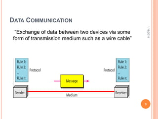
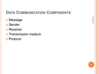
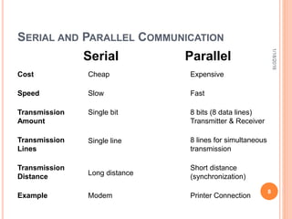
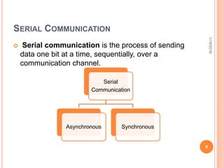
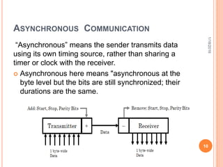
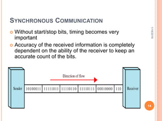
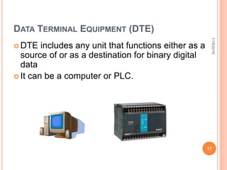
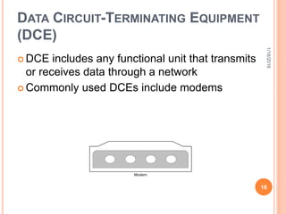
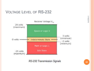
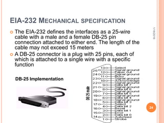
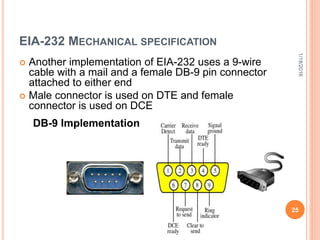
SERIAL COMMUNICATION
PRESENTED TO:
ENGINEERING DEPTT SEPL.
PRESENTED BY:
MUHAMMAD FAIZAN SALEEM
ALI RAZA
Presentation # 6
1
1/18/2016
CONTENTS
 Data Communication
 Components of Data Communication
 Data Flow
 Serial Communication
 Parallel Communication
 Types of Serial Communication
 Standard of serial Communication
2
1/18/2016
DATA COMMUNICATION
“Exchange of data between two devices via some
form of transmission medium such as a wire cable”
3
1/18/2016
DATA COMMUNICATION COMPONENTS
 Message
 Sender
 Receiver
 Transmission medium
 Protocol
4
1/18/2016
Data
Flow
Simplex
Half-
Duplex
Full-
Duplex
Simplex Communication is unidirectional. Only one of the two devices
on a link can transmit and the other can only receive (e.g.
monitor and keyboard)
Half-Duplex Each station can both transmit and receive, but not at the
same time. When one device is sending, the other can only
receive, and vice versa(Walkie-talkies)
Full Duplex Both stations can transmit and receive
simultaneously.(Telephone networks) 5
1/18/2016
DATA TRANSMISSION
The transmission of binary data across a link can be
accomplished either in parallel mode or serial mode
 In parallel mode, multiple bits are sent with each
clock pulse
 In serial mode, one bit is sent with each clock
pulse
6
1/18/2016
TRANSMISSION ILLUSTRATION
Serial
Receiver
Transmitter
Parallel
Receiver
Transmitter
1 bit
1 word
7
1/18/2016
Parallel
Serial
Cost
Speed
Transmission
Amount
Transmission
Lines
Transmission
Distance
Example
Cheap
Slow
Single bit
Single line
Long distance
Modem
Expensive
Fast
8 bits (8 data lines)
Transmitter & Receiver
8 lines for simultaneous
transmission
Short distance
(synchronization)
Printer Connection
8
SERIAL AND PARALLEL COMMUNICATION
1/18/2016
SERIAL COMMUNICATION
 Serial communication is the process of sending
data one bit at a time, sequentially, over a
communication channel.
Serial
Communication
Asynchronous Synchronous
9
1/18/2016
ASYNCHRONOUS COMMUNICATION
“Asynchronous” means the sender transmits data
using its own timing source, rather than sharing a
timer or clock with the receiver.
 Asynchronous here means "asynchronous at the
byte level but the bits are still synchronized; their
durations are the same.
10
1/18/2016
ASYNCHRONOUS COMMUNICATION
11
The Transmitter
o Also adds the start,
stop and parity check
bits
The Receiver
o Extracts the data using
its own clock
1/18/2016
 Start bit—indicates the beginning of the data word
 Stop bit—indicates the end of the data word
 Parity bit—added for error detection (optional)
ASYNCHRONOUS COMMUNICATION
12
 It is Cheap and
Effective.
 Used for long
transmission.
 Asynchronous
transmission is easy to
implement but less
efficient as it requires
an extra 2-3 control bits
for every 8 data bits
 This method is usually
used for low volume
transmission
Advantages Disadvantages
1/18/2016
SYNCHRONOUS COMMUNICATION
 In synchronous transmission, the bit stream is
combined into longer frames which may contains
multiple bytes
 It is the responsibility of the receiver to reconstruct
the information
13
1/18/2016
SYNCHRONOUS COMMUNICATION
14
 Without start/stop bits, timing becomes very
important
 Accuracy of the received information is completely
dependent on the ability of the receiver to keep an
accurate count of the bits.
1/18/2016
SYNCHRONOUS COMMUNICATION
 Advantage of synchronous transmission is speed.
 No extra bits to introduce at the sending end and
remove at the receiving end, and, by extension,
with
 Fewer bits to move across the link,
 For this reason, it is more useful for high-speed
applications (transmission of data from one
computer to another)
15
1/18/2016
16
DTE-DCE INTERFACE
 The DTE generates the data and pass them to a DCE. The DCE
converts the signal to a format appropriate to the transmission
medium
 When the signal arrives at the receiving end, this process is reversed
1/18/2016
17
DATA TERMINAL EQUIPMENT (DTE)
 DTE includes any unit that functions either as a
source of or as a destination for binary digital
data
 It can be a computer or PLC.
1/18/2016
18
DATA CIRCUIT-TERMINATING EQUIPMENT
(DCE)
 DCE includes any functional unit that transmits
or receives data through a network
 Commonly used DCEs include modems
Modem
1/18/2016
SERIAL COMMUNICATION PROTOCOLS
There are the following serial communication
protocols:
 EIA-232(RS-232)
 RS-422
 RS-485
19
1/18/2016
RS-232
Originally issued in 1962 as the RS-232 standard
(recommended standard)
Used for many purposes, such as connecting a
mouse, printer, or modem, as well as industrial
instrumentation
20
1/18/2016
ELECTRICAL SPECIFICATIONS
 EIA(Electronic Industries Association)-232 states
that all data must be transmitted as logical 1s and
0s
 0 defined as a positive voltage and 1 defined as a
negative voltage
 To be recognized as data, the amplitude of a signal
must fall between 3 and 25 volts or between -3 and
-25 volts
 EIA-232 allows for a maximum bit rate of 20 kbps
21
1/18/2016
VOLTAGE LEVEL OF RS-232
1/18/2016
22
RS-232
 Communication is completed using 3 transmission
lines:
 Ground
 Transmit
 Receive
 The port is able to transmit data on one line while
receiving data on another.
 Use unbalanced differential signals.
23
1/18/2016
EIA-232 MECHANICAL SPECIFICATION
 The EIA-232 defines the interfaces as a 25-wire
cable with a male and a female DB-25 pin
connection attached to either end. The length of the
cable may not exceed 15 meters
 A DB-25 connector is a plug with 25 pins, each of
which is attached to a single wire with a specific
function
24
DB-25 Implementation
1/18/2016
EIA-232 MECHANICAL SPECIFICATION
 Another implementation of EIA-232 uses a 9-wire
cable with a mail and a female DB-9 pin connector
attached to either end
 Male connector is used on DTE and female
connector is used on DCE
25
DB-9 Implementation
1/18/2016
RS-422 & RS-485
 RS-422 and RS-485 are the common names for
two serial communications standards.
 The standards, defined by the Electronics Industry
Association, are more correctly named EIA/TIA-422
and EIA/TIA-485.
 RS-422 and RS-485 communicate digital
information over twisted pair wire from transmitters
to receivers.
 Devices can be up to 4000 feet (1220 meters) apart
before repeaters are required.
1/18/2016
26
RS-422 & RS-485
 RS-422 drivers can transmit to up to 10 receivers.
Up to 32 RS-485 transceivers can occupy a bus.
 RS-422/485 systems can communicate at rates up
to 10 Mbps (though most systems operate at lower
bit rates).
 Both systems utilize balanced outputs and
differential inputs, which provide better noise
immunity than single-ended systems such as RS-
232.
1/18/2016
27
RS-422 & RS-485
 RS-422 also makes it possible to create point-to-
multipoint connections.
 In a point-to-multipoint arrangement the node
originating the data (master) can broadcast data to
several (slave) nodes at once.
 For the master to receive data back from each
slave, RS-485 devices are required.
 RS-422 and RS-485 contain balanced differential
signals.
1/18/2016
28
BALANCED DIFFERENTIAL SIGNALS
 Voltage produced by the driver appears across a
pair of signal lines.
 These lines produce complementary (opposite)
output signals.
 RS-422/RS-485 balanced data transmission also
requires a GND connection, even though the GND
connection is not used by the receiver to determine
the logic state of the data.
1/18/2016
29
VA - VB < -0.2V = "1"
VA - VB > 0.2V = "0"
Where VA and VB are the voltages on the "A" and "B"
lines respectively.
1/18/2016
30
2 & 4 WIRE CONNECTIONS
1/18/2016
31
PIN CONFIGURATION OF RS-422/485
32
1/18/2016
COMPARISON OF RS-232,422 & 485
RS-232 RS-422 RS-485
Line Configuration Single Ended Multi-drop Multi-drop
Maximum Cable
Length
50 ft 4000ft 4000ft
Maximum data
Rate
20kbites/s 10Mbites/s 10Mbites/s
Typical logic
levels
+/- 5 to +/-15 V +/-2 to +/-5 +/- 1.5 to
+/-6 V
Receiver
Sensitivity
+/-3 V +/-200mV +/- 200 mV
33
1/18/2016
34
1/18/2016

6.serial communication.pptx

  • 1.
    SERIAL COMMUNICATION PRESENTED TO: ENGINEERINGDEPTT SEPL. PRESENTED BY: MUHAMMAD FAIZAN SALEEM ALI RAZA Presentation # 6 1 1/18/2016
  • 2.
    CONTENTS  Data Communication Components of Data Communication  Data Flow  Serial Communication  Parallel Communication  Types of Serial Communication  Standard of serial Communication 2 1/18/2016
  • 3.
    DATA COMMUNICATION “Exchange ofdata between two devices via some form of transmission medium such as a wire cable” 3 1/18/2016
  • 4.
    DATA COMMUNICATION COMPONENTS Message  Sender  Receiver  Transmission medium  Protocol 4 1/18/2016
  • 5.
    Data Flow Simplex Half- Duplex Full- Duplex Simplex Communication isunidirectional. Only one of the two devices on a link can transmit and the other can only receive (e.g. monitor and keyboard) Half-Duplex Each station can both transmit and receive, but not at the same time. When one device is sending, the other can only receive, and vice versa(Walkie-talkies) Full Duplex Both stations can transmit and receive simultaneously.(Telephone networks) 5 1/18/2016
  • 6.
    DATA TRANSMISSION The transmissionof binary data across a link can be accomplished either in parallel mode or serial mode  In parallel mode, multiple bits are sent with each clock pulse  In serial mode, one bit is sent with each clock pulse 6 1/18/2016
  • 7.
  • 8.
    Parallel Serial Cost Speed Transmission Amount Transmission Lines Transmission Distance Example Cheap Slow Single bit Single line Longdistance Modem Expensive Fast 8 bits (8 data lines) Transmitter & Receiver 8 lines for simultaneous transmission Short distance (synchronization) Printer Connection 8 SERIAL AND PARALLEL COMMUNICATION 1/18/2016
  • 9.
    SERIAL COMMUNICATION  Serialcommunication is the process of sending data one bit at a time, sequentially, over a communication channel. Serial Communication Asynchronous Synchronous 9 1/18/2016
  • 10.
    ASYNCHRONOUS COMMUNICATION “Asynchronous” meansthe sender transmits data using its own timing source, rather than sharing a timer or clock with the receiver.  Asynchronous here means "asynchronous at the byte level but the bits are still synchronized; their durations are the same. 10 1/18/2016
  • 11.
    ASYNCHRONOUS COMMUNICATION 11 The Transmitter oAlso adds the start, stop and parity check bits The Receiver o Extracts the data using its own clock 1/18/2016  Start bit—indicates the beginning of the data word  Stop bit—indicates the end of the data word  Parity bit—added for error detection (optional)
  • 12.
    ASYNCHRONOUS COMMUNICATION 12  Itis Cheap and Effective.  Used for long transmission.  Asynchronous transmission is easy to implement but less efficient as it requires an extra 2-3 control bits for every 8 data bits  This method is usually used for low volume transmission Advantages Disadvantages 1/18/2016
  • 13.
    SYNCHRONOUS COMMUNICATION  Insynchronous transmission, the bit stream is combined into longer frames which may contains multiple bytes  It is the responsibility of the receiver to reconstruct the information 13 1/18/2016
  • 14.
    SYNCHRONOUS COMMUNICATION 14  Withoutstart/stop bits, timing becomes very important  Accuracy of the received information is completely dependent on the ability of the receiver to keep an accurate count of the bits. 1/18/2016
  • 15.
    SYNCHRONOUS COMMUNICATION  Advantageof synchronous transmission is speed.  No extra bits to introduce at the sending end and remove at the receiving end, and, by extension, with  Fewer bits to move across the link,  For this reason, it is more useful for high-speed applications (transmission of data from one computer to another) 15 1/18/2016
  • 16.
    16 DTE-DCE INTERFACE  TheDTE generates the data and pass them to a DCE. The DCE converts the signal to a format appropriate to the transmission medium  When the signal arrives at the receiving end, this process is reversed 1/18/2016
  • 17.
    17 DATA TERMINAL EQUIPMENT(DTE)  DTE includes any unit that functions either as a source of or as a destination for binary digital data  It can be a computer or PLC. 1/18/2016
  • 18.
    18 DATA CIRCUIT-TERMINATING EQUIPMENT (DCE) DCE includes any functional unit that transmits or receives data through a network  Commonly used DCEs include modems Modem 1/18/2016
  • 19.
    SERIAL COMMUNICATION PROTOCOLS Thereare the following serial communication protocols:  EIA-232(RS-232)  RS-422  RS-485 19 1/18/2016
  • 20.
    RS-232 Originally issued in1962 as the RS-232 standard (recommended standard) Used for many purposes, such as connecting a mouse, printer, or modem, as well as industrial instrumentation 20 1/18/2016
  • 21.
    ELECTRICAL SPECIFICATIONS  EIA(ElectronicIndustries Association)-232 states that all data must be transmitted as logical 1s and 0s  0 defined as a positive voltage and 1 defined as a negative voltage  To be recognized as data, the amplitude of a signal must fall between 3 and 25 volts or between -3 and -25 volts  EIA-232 allows for a maximum bit rate of 20 kbps 21 1/18/2016
  • 22.
    VOLTAGE LEVEL OFRS-232 1/18/2016 22
  • 23.
    RS-232  Communication iscompleted using 3 transmission lines:  Ground  Transmit  Receive  The port is able to transmit data on one line while receiving data on another.  Use unbalanced differential signals. 23 1/18/2016
  • 24.
    EIA-232 MECHANICAL SPECIFICATION The EIA-232 defines the interfaces as a 25-wire cable with a male and a female DB-25 pin connection attached to either end. The length of the cable may not exceed 15 meters  A DB-25 connector is a plug with 25 pins, each of which is attached to a single wire with a specific function 24 DB-25 Implementation 1/18/2016
  • 25.
    EIA-232 MECHANICAL SPECIFICATION Another implementation of EIA-232 uses a 9-wire cable with a mail and a female DB-9 pin connector attached to either end  Male connector is used on DTE and female connector is used on DCE 25 DB-9 Implementation 1/18/2016
  • 26.
    RS-422 & RS-485 RS-422 and RS-485 are the common names for two serial communications standards.  The standards, defined by the Electronics Industry Association, are more correctly named EIA/TIA-422 and EIA/TIA-485.  RS-422 and RS-485 communicate digital information over twisted pair wire from transmitters to receivers.  Devices can be up to 4000 feet (1220 meters) apart before repeaters are required. 1/18/2016 26
  • 27.
    RS-422 & RS-485 RS-422 drivers can transmit to up to 10 receivers. Up to 32 RS-485 transceivers can occupy a bus.  RS-422/485 systems can communicate at rates up to 10 Mbps (though most systems operate at lower bit rates).  Both systems utilize balanced outputs and differential inputs, which provide better noise immunity than single-ended systems such as RS- 232. 1/18/2016 27
  • 28.
    RS-422 & RS-485 RS-422 also makes it possible to create point-to- multipoint connections.  In a point-to-multipoint arrangement the node originating the data (master) can broadcast data to several (slave) nodes at once.  For the master to receive data back from each slave, RS-485 devices are required.  RS-422 and RS-485 contain balanced differential signals. 1/18/2016 28
  • 29.
    BALANCED DIFFERENTIAL SIGNALS Voltage produced by the driver appears across a pair of signal lines.  These lines produce complementary (opposite) output signals.  RS-422/RS-485 balanced data transmission also requires a GND connection, even though the GND connection is not used by the receiver to determine the logic state of the data. 1/18/2016 29
  • 30.
    VA - VB< -0.2V = "1" VA - VB > 0.2V = "0" Where VA and VB are the voltages on the "A" and "B" lines respectively. 1/18/2016 30
  • 31.
    2 & 4WIRE CONNECTIONS 1/18/2016 31
  • 32.
    PIN CONFIGURATION OFRS-422/485 32 1/18/2016
  • 33.
    COMPARISON OF RS-232,422& 485 RS-232 RS-422 RS-485 Line Configuration Single Ended Multi-drop Multi-drop Maximum Cable Length 50 ft 4000ft 4000ft Maximum data Rate 20kbites/s 10Mbites/s 10Mbites/s Typical logic levels +/- 5 to +/-15 V +/-2 to +/-5 +/- 1.5 to +/-6 V Receiver Sensitivity +/-3 V +/-200mV +/- 200 mV 33 1/18/2016
  • 34.

Editor's Notes

  • #5 Message. The message is the information (data) to be communicated. Popular forms of information include text, numbers, pictures, audio, and video. Sender. The sender is the device that sends the data message. It can be a computer, workstation, telephone handset, video camera, and so on. Receiver. The receiver is the device that receives the message. I t can be a computer, workstation, telephone handset, television, and so on. -1.. Transmission medium. The transmission medium is the physical path by which a message travels f rom sender to receiver. Some examples of transmission media include twisted-pair wire, coaxial cable, fiber-optic cable, and radio waves. SECTION 1.1 DATA COMMUNICATIONS 5 5. Protocol. A protocol is a set of rules that govern data communications. It represents an agreement between the communicating devices. Without a protocol, two devices may be connected but not communicating, just as a person speaking French cannot be understood by a person who speaks only Japanese