1. Function overview
Description
Siemens SIP · 2006
11 Generator Protection / 7UM62
11
11/33
Standard version
Scope of basic version plus:
• Inadvertent energization protection
• 100 %-stator earth-fault protection
with 3rd harmonic
• Impedance protection
Full version
Scope of standard version plus:
• DC voltage protection
• Overcurrent protection during start-ups
• Earth-current differential protection
• Out-of-step protection
Additional version
Available for each version:
• Sensitive rotor earth-fault protection
(1-3 Hz method)
• Stator earth-fault protection with
20 Hz voltage
• Rate-of-frequency-change protection
• Vector jump supervision
Monitoring function
• Trip circuit supervision
• Fuse failure monitor
• Operational measured values V, I, f, …
• Energy metering values Wp, Wq
• Time metering of operating hours
• Self-supervision of relay
• 8 oscillographic fault records
Communication interfaces
• System interface
– IEC 61850 protocol
– IEC 60870-5-103 protocol
– PROFIBUS-DP
– MODBUS RTU
– DNP 3.0
Hardware
• Analog inputs
• 8 current transformers
• 4 voltage transformers
• 7/15 binary inputs
• 12/20 output relays
Front design
• User-friendly local operation
• 7/14 LEDs for local alarm
• Function keys
• Graphic display with 7UM623
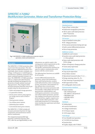
SIPROTEC 4 7UM62
Multifunction Generator, Motor and Transformer Protection Relay
The SIPROTEC 4 7UM62 protection relays
can do more than just protect. They also
offer numerous additional functions. Be it
earth faults, short-circuits, overloads, over-
voltage, overfrequency or underfrequency
asynchronous conditions, protection relays
assure continued operation of power sta-
tions. The SIPROTEC 4 7UM62 protection
relay is a compact unit which has been
specially developed and designed for the
protection of small, medium-sized and
large generators. They integrate all the
necessary protection functions and are par-
ticularly suited for the protection of:
− Hydro and pumped-storage generators
− Co-generation stations
− Private power stations using regenera-
tive energy sources such as wind or
biogases
− Diesel generator stations
− Gas-turbine power stations
− Industrial power stations
− Conventional steam power stations.
The SIPROTEC 4 7UM62 includes all
necessary protection functions for large
synchronous and asynchronous motors
and for transformers.
The integrated programmable logic
functions (continuous function chart
CFC) offer the user high flexibility so that
Fig. 11/35 SIPROTEC 4 7UM62 multifunction protection relay for
generators, motors and transformers
LSP2171-afpen.eps
adjustments can easily be made to the
varying power station requirements on the
basis of special system conditions.
The flexible communication interfaces are
open for modern communication archi-
tectures with the control system.
The following basic functions are available
for all versions:
Current differential protection for
generators, motors and transformers,
stator earth-fault protection, sensitive
earth-fault protection, stator overload pro-
tection, overcurrent- time protection (ei-
ther definite time or inverse time),
definite-time overcurrent protection with
directionality, undervoltage and overvolt-
age protection, underfrequency and
overfrequency protection, overexcitation
and underexcitation protection, external
trip coupling, forward-power and reverse-
power protection, negative-sequence pro-
tection, breaker failure protection, rotor
earth-faults protection (fn, R-measuring),
motor starting time supervision and restart
inhibit for motors.
2. The 7UM6 protection relays of the
SIPROTEC 4 family are compact multi-
function units which have been developed
for small to medium-sized power genera-
tion plants. They incorporate all the neces-
sary protective functions and are especially
suitable for the protection of:
– Hydro and pumped-storage generators
– Co-generation stations
– Private power stations using regenera-
tive energy sources such as wind or
biogases
– Power generation with diesel
generators
– Gas turbine power stations
– Industrial power stations
– Conventional steam power stations.
They can also be employed for protection
of motors and transformers.
The numerous other additional functions
assist the user in ensuring cost-effective
system management and reliable power
supply. Measured values display current
operating conditions. Stored status indica-
tions and fault recording provide assistance
in fault diagnosis not only in the event of a
disturbance in generator operation.
Combination of the units makes it possible
to implement effective redundancy con-
cepts.
Protection functions
Numerous protection functions are neces-
sary for reliable protection of electrical ma-
chines. Their extent and combination are
determined by a variety of factors, such as
machine size, mode of operation, plant
configuration, availability requirements,
experience and design philosophy.
This results in multifunctionality, which is
implemented in outstanding fashion by
numerical technology.
In order to satisfy differing requirements,
the combination of functions is scalable
(see Table 11/3). Selection is facilitated by
division into five groups.
Generator Basic
One application concentrates on small and
medium generators for which differential
protection is required. The function mix is
also suitable as backup protection. Protec-
tion of synchronous motors is a further ap-
plication.
Generator Standard
In the case of medium-size generators
(10 to 100 MVA) in a unit connection, this
scope of functions offers all necessary
protection functions. Besides inadvertent
energization protection, it also includes
powerful backup protection for the trans-
former or the power system. The scope of
protection is also suitable for units in the
second protection group.
Generator Full
Here, all protection functions are available
and the main application focuses on large
block units (more than 100 MVA). The
function mix includes all necessary protec-
tion functions for the generator as well as
backup protection for the block trans-
former including the power system. Addi-
tional functions such as protection during
start-up for generators with starting con-
verters are also included.
The scope of functions can be used for the
second protection group, and functions
that are not used, can be masked out.
Asynchronous motor
Besides differential protection, this func-
tion package includes all protection func-
tions needed to protect large asynchronous
motors (more than 1 MVA). Stator and
bearing temperatures are measured by a
separate thermo-box and are transmitted
serially to the protection unit for evalua-
tion.
Transformer
This scope of functions not only includes
differential and overcurrent protection,
but also a number of protection functions
that permit monitoring of voltage and fre-
quency stress, for instance. The reverse-
power protection can be used for energy
recovery monitoring of parallel-connected
transformers.
Siemens SIP · 2006
11 Generator Protection / 7UM62
11
11/34
Application Construction
Fig. 11/36
Rear view with wiring terminal
safety cover and serial interface
The SIPROTEC 4 units have a uniform
design and a degree of functionality which
represents a whole new quality in protec-
tion and control.
Local operation has been designed accord-
ing to ergonomic criteria. Large, easy-to-
read displays were a major design aim. The
7UM623 is equipped with a graphic display
thus providing and depicting more infor-
mation especially in industrial applica-
tions. The DIGSI 4 operating program
considerably simplifies planning and engi-
neering and reduces commissioning times.
The 7UM621 and 7UM623 are configured
in 1/2 19 inches width. This means that the
units of previous models can be replaced.
The height throughout all housing width
increments is 243 mm.
All wires are connected directly or by
means of ring-type cable lugs. Alterna-
tively, versions with plug-in terminals are
also available. These permit the use of
prefabricated cable harnesses.
In the case of panel surface mounting, the
connecting terminals are in the form of
screw-type terminals at top and bottom.
The communication interfaces are also
arranged on the same sides.
LSP2166-afpen.eps
3. Siemens SIP · 2006
11 Generator Protection / 7UM62
11
11/35
Protection functions
Protection functions Abbre-
viation
ANSI No. Gene-
rator
Basic
Gene-
rator
Standard
Gene-
rator
Full
Motor
Asyn-
chronous
Trans-
former
Current differential protection ∆ I 87G/87T/87M X X X X X
Stator earth-fault protection
non-directional, directional
V0>, 3I0>
(V0, 3I0)
59N, 64G
67G
X X X X X
Sensitive earth-fault protection
(also rotor earth-fault protection)
IEE> 50/51GN
(64R)
X X X X X
Sensitive earth-fault prot. B (e.g. shaft current prot.) IEE-B> IEE-B< 51GN X X X X X
Stator overload protection I
2
t 49 X X X X X
Definite-time overcurrent prot. with undervolt. seal-in I> +V< 51 X X X X X
Definite-time overcurrent protection, directional I>>, Direc. 50/51/67 X X X X X
Inverse-time overcurrent protection t = f (I)+V< 51V X X X X X
Overvoltage protection V> 59 X X X X X
Undervoltage protection V<, t = f (V) 27 X X X X X
Frequency protection f<, f> 81 X X X X X
Reverse-power protection -P 32R X X X X X
Overexcitation protection (Volt/Hertz) V/f 24 X X X X X
Fuse failure monitor V2/V1, I2/I1 60FL X X X X X
External trip coupling Incoup. 4 4 4 4 4
Trip circuit supervision T.C.S. 74TC X X X X X
Forward-power protection P>, P< 32F X X X X X
Underexcitation protection (loss-of-field protection) 1/xd 40 X X X
Negative-sequence protection I2>, t = f (I2) 46 X X X X
Breaker failure protection Imin> 50BF X X X X X
Motor starting time supervision Istart
2
t 48 X X X X
Restart inhibit for motors I
2
t 66, 49 Rotor X X X X
Rotor earth-fault protection (fn, R-measuring) R< 64R (fn) X X X
Inadvertent energization protection I>, V< 50/27 X X
100 % stator earth-fault protection
with 3
rd
harmonics
V0(3rd harm.) 59TN, 27TN 3
rd
h
X X
Impedance protection with (I>+V<) pickup Z< 21 X X
Interturn protection UInterturn> 59N(IT) X X
DC voltage / DC current time protection Vdc >
Idc >
59N (DC)
51N (DC)
X
Overcurrent protection during startup
(for gas turbines)
I> 51 X
Earth-current differential protection ∆Ie 87GN/TN X
1)
X
1)
X X
1)
X
1)
Out-of-step protection ∆Z/∆t 78 X
Rotor earth-fault protection (1-3 Hz square wave voltage) RREF< 64R (1–3 Hz) X
1)
X
1)
X
1)
100 % stator earth-fault protection with 20 Hz voltage RSEF< 64G (100 %) X
1)
X
1)
X
1)
Rate-of-frequency-change protection df/dt > 81R X
1)
X
1)
X
1)
X
1)
X
1)
Vector jump supervision (voltage) ∆ > X
1)
X
1)
X
1)
X
1)
X
1)
Threshold supervision X X X X X
Supervision of phase rotation A, B, C 47 X X X X X
Undercurrent via CFC I < 37 X X X X X
External temperature monitoring via serial interface (Thermo-box) 38 X X X X X
Table 11/3 Scope of functions of the 7UM62
1) Optional for all function groups.
4. Current differential protection
(ANSI 87G, 87M, 87T)
This function provides undelayed short-cir-
cuit protection for generators, motors and
transformers, and is based on the current
differential protection principle (Kirchhoff’s
current law).
The differential and restraint (stabilization)
current are calculated on the basis of the
phase currents. Optimized digital filters reli-
ably attenuate disturbances such as aperio-
dic component and harmonics. The high
resolution of measured quantities permits
recording of low differential currents (10 %
of IN) and thus a very high sensitivity.
An adjustable restraint characteristic per-
mits optimum adaptation to the conditions
of the protected object. Software is used to
correct the possible mismatch of the current
transformers and the phase angle rotation
through the transformer (vector group).
Thanks to harmonic analysis of the differen-
tial current, inrush (second harmonic) and
overexcitation (fifth harmonic) are reliably
detected, and unwanted operation of the
differential protection is prevented. The
current of internal short-circuits is reliably
measured by a fast measuring stage
(1Diff>>), which operates with two mutually
complementary measuring processes. An
external short-circuit with transformer satu-
ration is picked up by a saturation detector
with time and status monitoring. It becomes
active when the differential current (IDiff)
moves out of the add-on restraint area.
If a motor is connected, this is detected by
monitoring the restraint current and the
restraint characteristic is briefly raised.
This prevents false tripping in the event of
unequal current transmission by the cur-
rent transformers.
Figure 11/37 shows the restraint
characteristic and various areas.
Earth-current differential protection
(ANSI 87GN, 87TN)
The earth-current differential protection
permits high sensitivity to single-pole faults.
The zero currents are compared. On the one
hand, the zero-sequence current is calcu-
lated on the basis of the phase currents and
on the other hand, the earth current is mea-
sured directly at the star-point current
transformer.
The differential and restraint quantity is
generated and fitted into the restraint
characteristic (see Fig. 11/38).
DC components in particular are sup-
pressed by means of specially dimensioned
filters. A number of monitoring proc-
esses avoid unwanted operation in the event
of external short-circuits. In the case of a
sensitive setting, multiple measurement
ensures the necessary reliability.
However, attention must be drawn to the
fact that the sensitivity limits are determined
by the current transformers.
The protection function is only used on
generators when the neutral point is
earthed with a low impedance. In the case
of transformers, it is connected on the neu-
tral side. Low impedance or solid earthing
is also required.
Siemens SIP · 2006
11 Generator Protection / 7UM62
11
11/36
Protection functions
Fig. 11/37 Restraint characteristic of current differential protection
Fig. 11/38 Restraint characteristic of earth-current differential protection
5. Definite-time overcurrent protection
I>, I>> (ANSI 50, 51, 67)
This protection function comprises the
short-circuit protection for the generator
and also the backup protection for up-
stream devices such as transformers or
power system protection.
An undervoltage stage at I> maintains the
pickup when, during the fault, the current
drops below the threshold. In the event of a
voltage drop on the generator terminals, the
static excitation system can no longer be
sufficiently supplied. This is one reason for
the decrease of the short-circuit current.
The I>> stage can be implemented as
high-set instantaneous trip stage. With the
integrated directional function it can be
used as backup protection on the trans-
former high-voltage side. With the infor-
mation of the directional element,
impedance protection can be controlled
via the CFC.
Inverse-time overcurrent protection
(ANSI 51V)
This function also comprises short-circuit
and backup protection and is used for
power system protection with current-
dependent protection devices.
IEC and ANSI characteristics can be
selected (Table 11/4).
The current function can be controlled by
evaluating the generator terminal voltage.
The “controlled” version releases the
sensitive set current stage.
With the “restraint” version, the pickup
value of the current is lowered linearly with
decreasing voltage.
The fuse failure monitor prevents
unwanted operation.
Stator overload protection (ANSI 49)
The task of the overload protection is to
protect the stator windings of generators
and motors from high, continuous over-
load currents. All load variations are evalu-
ated by a mathematical model. The
thermal effect of the r.m.s. current value
forms the basis of the calculation.
This conforms to IEC 60255-8.
In dependency of the current, the cooling
time constant is automatically extended. If
the ambient temperature or the tempera-
ture of the coolant are injected via a trans-
ducer (TD2) or PROFIBUS-DP, the model
automatically adapts to the ambient condi-
tions; otherwise a constant ambient tem-
perature is assumed.
Negative-sequence protection (ANSI 46)
Asymmetrical current loads in the three
phases of a generator cause a temperature
rise in the rotor because of the negative-
sequence field produced.
This protection detects an asymmetrical
load in three-phase generators. It functions
on the basis of symmetrical components
and evaluates the negative sequence of the
phase currents. The thermal processes are
taken into account in the algorithm and
form the inverse characteristic. In addition,
the negative sequence is evaluated by an in-
dependent stage (alarm and trip) which is
supplemented by a time-delay element (see
Figure 11/39). In the case of motors, the
protection function is also used to monitor
a phase failure.
Siemens SIP · 2006
11 Generator Protection / 7UM62
11
11/37
Protection functions
Fig. 11/39 Characteristic of negative-sequence protection
Available inverse-time characteristics
Characteristics ANSI IEC 60255-3
Inverse • •
Moderately inverse •
Very inverse • •
Extremely inverse • •
Definite inverse •
Table 11/4
Underexcitation protection
(Loss-of-field protection) (ANSI 40)
Derived from the generator terminal voltage
and current, the complex admittance is cal-
culated and corresponds to the generator
diagram scaled in per unit. This protection
prevents damage due to loss of synchronism
resulting from underexcitation. The protec-
tion function provides three characteristics
for monitoring static and dynamic stability.
Via a transducer, the excitation voltage (see
Figure 11/54) can be injected and, in the
event of failure, a swift reaction of the pro-
tection function can be achieved by timer
changeover.
The straight-line characteristics allow the
protection to be optimally adapted to the
generator diagram (see Figure 11/40). The
per-unit-presentation of the diagram allows
the setting values to be directly read out.
The positive-sequence systems of current
and voltage are used to calculate the admit-
tance. This ensures that the protection al-
ways operates correctly even with asymme-
trical network conditions.
If the voltage deviates from the rated volt-
age, the admittance calculation has the ad-
vantage that the characteristics move in the
same direction as the generator diagram.
6. Reverse-power protection (ANSI 32R)
The reverse-power protection monitors the
direction of active power flow and picks up
when the mechanical energy fails. This
function can be used for operational shut-
down (sequential tripping) of the genera-
tor but also prevents damage to the steam
turbines. The reverse power is calculated
from the positive-sequence systems of cur-
rent and voltage. Asymmetrical power sys-
tem faults therefore do not cause reduced
measuring accuracy. The position of the
emergency trip valve is injected as binary
information and is used to switch between
two trip command delays. When applied
for motor protection, the sign (±) of the
active power can be reversed via parame-
ters.
Forward-power protection (ANSI 32F)
Monitoring of the active power produced
by a generator can be useful for starting up
and shutting down generators. One stage
monitors exceeding of a limit value, while
another stage monitors falling below an-
other limit value. The power is calculated
using the positive-sequence component of
current and voltage. The function can be
used to shut down idling motors.
Impedance protection (ANSI 21)
This fast short-circuit protection protects
the generator and the unit transformer and
is a backup protection for the power system.
This protection has two settable impedance
stages; in addition, the first stage can be
switched over via binary input. With the cir-
cuit-breaker in the “open” position the im-
pedance measuring range can be extended
(see Figure 11/41).
The overcurrent pickup element with
undervoltage seal-in ensures a reliable
pickup and the loop selection logic ensures
a reliable detection of the faulty loop. With
this logic it is possible to perform correct
measurement via the unit transformer.
Undervoltage protection (ANSI 27)
The undervoltage protection evaluates the
positive-sequence components of the volt-
ages and compares them with the threshold
values. There are two stages available.
The undervoltage function is used for asyn-
chronous motors and pumped-storage sta-
tions and prevents the voltage-related insta-
bility of such machines.
The function can also be used for monitor-
ing purposes.
Overvoltage protection (ANSI 59)
This protection prevents insulation faults
that result when the voltage is too high.
Either the maximum line-to-line voltages
or the phase-to-earth voltages (for low-
voltage generators) can be evaluated. The
measuring results of the line-to-line volt-
ages are independent of the neutral point
displacement caused by earth faults. This
function is implemented in two stages.
Frequency protection (ANSI 81)
The frequency protection prevents imper-
missible stress of the equipment (e.g. tur-
bine) in case of under or overfrequency. It
also serves as a monitoring and control ele-
ment.
The function has four stages; the stages can
be implemented either as underfrequency
or overfrequency protection. Each stage
can be delayed separately.
Even in the event of voltage distortion, the
frequency measuring algorithm reliably
identifies the fundamental waves and de-
termines the frequency extremely precisely.
Frequency measurement can be blocked by
using an undervoltage stage.
Overexcitation protection Volt/Hertz
(ANSI 24)
The overexcitation protection serves for de-
tection of an unpermissible high induction
(proportional to V/f) in generators or trans-
formers, which leads to thermal overload-
ing. This may occur when starting up,
shutting down under full load, with weak
systems or under isolated operation. The in-
verse characteristic can be set via eight
points derived from the manufacturer data.
In addition, a definite-time alarm stage
and an instantaneous stage can be used.
For calculation of the V/f ratio, frequency
and also the highest of the three line-to-
line voltages are used. The frequency range
that can be monitored comprises 11 to
69 Hz.
Siemens SIP · 2006
11 Generator Protection / 7UM62
11
11/38
Protection functions
Fig. 11/40
Characteristic of underexcitation
protection
Fig. 11/41
Grading of impedance protection
7. 90 % stator earth-fault protection, non-di-
rectional, directional (ANSI 59N, 64G, 67G)
Earth faults manifest themselves in genera-
tors that are operated in isolation by the
occurence of a displacement voltage. In case
of unit connections, the displacement volt-
age is an adequate, selective criterion for
protection.
For the selective earth-fault detection, the
direction of the flowing earth current has to
be evaluated too, if there is a direct connec-
tion between generator and busbar.
The protection relay measures the displace-
ment voltage at a VT located at the trans-
former star point or at the broken delta
winding of a VT As an option, it is also pos-
sible to calculate the zero-sequence voltage
from the phase-to-earth voltages.
Depending on the load resistor selection, 90
to 95 % of the stator winding of a generator
can be protected.
A sensitive current input is available for
earth-current measurement. This input
should be connected to a core-balance cur-
rent transformer. The fault direction is de-
duced from the displacement voltage and
earth current. The directional characteristic
(straight line) can be easily adapted to the
system conditions. Effective protection for
direct connection of a generator to a busbar
can therefore be established. During start-
up, it is possible to switch over from the di-
rectional to the displacement voltage mea-
surement via an externally injected signal.
Depending on the protection setting,
various earth-fault protection concepts can
be implemented with this function
(see Figures 11/52 to 11/55).
Sensitive earth-fault protection
(ANSI 50/51GN, 64R)
The sensitive earth-current input can also
be used as separate earth-fault protection. It
is of two-stage form. Secondary earth cur-
rents of 2 mA or higher can be reliably han-
dled.
Alternatively, this input is also suitable as
rotor earth-fault protection. A voltage with
rated frequency (50 or 60 Hz) is connected
in the rotor circuit via the interface unit
7XR61. If a higher earth current is flowing,
a rotor earth fault has occurred. Measuring
circuit monitoring is provided for this ap-
plication (see Figure 11/58).
100 % stator earth-fault protection with 3
harmonic (ANSI 59TN, 27TN (3
rd
H.))
Owing to the creative design, the generator
produces a 3rd
harmonic that forms a zero
phase-sequence system. It is verifiable by the
protection on a broken delta winding or on
the neutral transformer. The magnitude of
the voltage amplitude depends on the gen-
erator and its operation.
In the event of an earth fault in the vicinity
of the neutral point, there is a change in the
amplitude of the 3rd
harmonic voltage
(dropping in the neutral point and rising at
the terminals).
Depending on the connection the protec-
tion must be set either as undervoltage or
overvoltage protection. It can also be de-
layed. So as to avoid overfunction, the active
power and the positive-sequence voltage act
as enabling criteria.
The picked-up threshold of the voltage stage
is restrained by the active power. This in-
creases sensitivity at low load.
The final protection setting can be made
only by way of a primary test with the gen-
erator.
Breaker failure protection (ANSI 50BF)
In the event of scheduled downtimes or a
fault in the generator, the generator can re-
main on line if the circuit-breaker is defec-
tive and could suffer substantial damage.
Breaker failure protection evaluates a mini-
mum current and the circuit-breaker aux-
iliary contact. It can be started by internal
protective tripping or externally via binary
input. Two-channel activation avoids
overfunction (see Figure 11/42).
Inadvertent energization protection
(ANSI 50, 27)
This protection has the function of limiting
the damage of the generator in the event of
an unintentional switch-on of the circuit-
breaker, whether the generator is standing
still or rotating without being excited or
synchronized. If the power system voltage is
connected, the generator starts as an asyn-
chronous machine with a large slip and this
leads to excessively high currents in the
rotor.
A logic circuit consisting of sensitive cur-
rent measurement for each phase, mea-
sured value detector, time control and
blocking as of a minimum voltage, leads to
an instantaneous trip command. If the fuse
failure monitor responds, this function is
ineffective.
Rotor earth-fault protection (ANSI 64R)
This protection function can be realized in
three ways with the 7UM62. The simplest
form is the method of rotor-current mea-
surement (see sensitive earth-current mea-
surement).
Resistance measurement at system-
frequency voltage
The second form is rotor earth resistance
measurement with voltage at system fre-
quency (see Fig. 11/58). This protection
measures the voltage injected and the flow-
ing rotor earth current. Taking into ac-
count the complex impedance from the
coupling device (7XR61), the rotor earth
resistance is calculated by way of a mathe-
matical model. By means of this method,
the disturbing influence of the rotor earth
capacitance is eliminated, and sensitivity is
increased. Fault resistance values up to
30 kΩ can be measured if the excitation
voltage is without disturbances. Thus, a
two-stage protection function, which fea-
tures a warning and a tripping stage, can be
realized. An additionally implemented un-
dercurrent stage monitors the rotor circuit
for open circuit and issues an alarm.
Siemens SIP · 2006
11 Generator Protection / 7UM62
11
11/39
Protection functions
Fig. 11/42
Logic diagram of breaker
failure protection
8. Resistance measurement with a square wave
voltage of 1 to 3 Hz
A higher sensitivity is required for larger
generators. On the one hand, the disturbing
influence of the rotor earth capacitance
must be eliminated more effectively and, on
the other hand, the noise ratio with respect
to the harmonics (e.g. sixth harmonic) of
the excitation equipment must be increased.
Injecting a low-frequency square wave volt-
age into the rotor circuit has proven itself
excellently here (see Figure 11/59).
The square wave voltage injected through
the controlling unit 7XT71 leads to perma-
nent recharging of the rotor earth capaci-
tance. By way of a shunt in the controlling
unit, the flowing earth current is measured
and is injected into the protection unit
(measurement input). In the absence of a
fault (RE
≈ ∞), the rotor earth current after
charging of the earth capacitance is close to
zero. In the event of an earth fault, the
fault resistance including the coupling re-
sistance (7XR6004), and also the injecting
voltage, defines the stationary current. The
current square wave voltage and the fre-
quency are measured via the second input
(control input). Fault resistance values up
to 80 kΩ can be measured by this measure-
ment principle. The rotor earth circuit is
monitored for discontinuities by evalua-
tion of the current during the polarity re-
versals.
100% stator earth-fault protection with
20 Hz injection (ANSI 64 G (100%))
Injecting a 20 Hz voltage to detect earth
faults even at the neutral point of generators
has proven to be a safe and reliable method.
Contrary to the third harmonic criterion
(see page 11/8), it is independent of the gen-
erator’s characteristics and the mode of op-
eration. Measurement is also possible
during system standstill (Fig. 11/57).
This protection function is designed so as to
detect both earth faults in the entire genera-
tor (genuine 100 %) and all electrically con-
nected system components.
The protection unit measures the injected
20 Hz voltage and the flowing 20 Hz cur-
rent. The disturbing variables, for example
stator earth capacitance, are eliminated by
way of a mathematical model, and the
ohmic fault resistance is determined.
On the one hand, this ensures high sensitiv-
ity and, on the other hand, it permits use of
generators with large earth capacitance val-
ues, e.g. large hydroelectric generators.
Phase-angle errors through the earthing or
neutral transformer are measured during
commissioning and are corrected in the al-
gorithm.
The protection function has a warning and
tripping stage. The measurement circuit is
also monitored and failure of the 20 Hz
generator is measured.
Independent of earth resistance calcula-
tion, the protection function additionally
evaluates the amount of the r.m.s. current
value.
Starting time supervision (motor protection
only) (ANSI 48)
Starting time supervision protects the motor
against long unwanted start-ups, which
might occur as a result of excessive load
torque or excessive voltage drops within the
motor, or if the rotor is locked.
The tripping time is dependent on the
square of the start-up current and the set
start-up time (Inverse Characteristic). It
adapts itself to the start-up with reduced
voltage. The tripping time is determined in
accordance with the following formula:
t tTrip
start
rms
start max=
⋅
I
I
2
tTrip Tripping time
Istart Permissible start-up current
tstart max Permissible start-up time
Irms Measured r.m.s. current value
Calculation is not started until the current
Irms is higher than an adjustable response
value (e.g. 2 IN, MOTOR).
If the permissible locked-rotor time is less
than the permissible start-up time (motors
with a thermally critical rotor), a binary
signal is set to detect a locked rotor by
means of a tachometer generator. This bi-
nary signal releases the set locked-rotor
time, and tripping occurs after it has
elapsed.
DC voltage time protection/DC current time
protection (ANSI 59N (DC) 51N (DC))
Hydroelectric generators or gas turbines are
started by way of frequency starting con-
verters. An earth fault in the intermediate
circuit of the frequency starting converter
causes DC voltage displacement and thus a
direct current. As the neutral or earthing
transformers have a lower ohmic resistance
than the voltage transformers, the largest
part of the direct current flows through
them, thus posing a risk of destruction from
thermal overloading.
As shown in Fig. 11/57, the direct current
is measured by means of a shunt trans-
former (measuring transducer) connected
directly to the shunt. Voltages or currents
are fed to the 7UM62 depending on the
version of the measuring transducer. The
measurement algorithm filters out the DC
component and takes the threshold value
decision. The protection function is active
as from 0 Hz.
If the measuring transducer transmits a
voltage for protection, the connection must
be interference-free and must be kept short.
The implemented function can also be
used for special applications. Thus, the
r.m.s. value can be evaluated for the quan-
tity applied at the input over a wide fre-
quency range.
Overcurrent protection during start-up
(ANSI 51)
Gas turbines are started by means of fre-
quency starting converters. Overcurrent
protection during start-up measures short-
circuits in the lower frequency level (as
from about 5 Hz) and is designed as inde-
pendent overcurrent-time protection. The
pickup value is set below the rated current.
The function is only active during start-up.
If frequencies are higher than 10 Hz, sam-
pling frequency correction takes effect and
the further short-circuit protection func-
tions are active.
Out-of-step protection (ANSI 78)
This protection function serves to measure
power swings in the system. If generators
feed to a system short-circuit for too long,
low frequency transient phenomena (active
power swings) between the system and the
generator may occur after fault clearing. If
the center of power swing is in the area of
the block unit, the “active power surges”
lead to unpermissible mechanical stressing
of the generator and the turbine.
As the currents and voltages are symmetri-
cal, the positive-sequence impedance is
calculated on the basis of their positive-
sequence components and the impedance
trajectory is evaluated. Symmetry is also
monitored by evaluation of the negative-
phase-sequence current. Two characteris-
tics in the R/X diagram describe the active
range (generator, unit transformer or
power system) of the out-of-step protec-
tion. The associated counters are incre-
mented depending on the range of the
characteristic in which the impedance
vector enters or departs. Tripping occurs
when the set counter value is reached.
Siemens SIP · 2006
11 Generator Protection / 7UM62
11
11/40
Protection functions
9. The counters are automatically reset if
power swing no longer occurs after a set
time. By means of an adjustable pulse, ev-
ery power swing can be signaled. Expan-
sion of the characteristic in the R direction
defines the power swing angle that can be
measured. An angle of 120 ° is practicable.
The characteristic can be tilted over an ad-
justable angle to adapt to the conditions
prevailing when several parallel generators
feed into the system.
Inverse undervoltage protection (ANSI 27)
Motors tend to fall out of step when their
torque is less than the breakdown torque.
This, in turn, depends on the voltage. On
the one hand, it is desirable to keep the mo-
tors connected to the system for as long as
possible while, on the other hand, the
torque should not fall below the breakdown
level. This protection task is realized by in-
verse undervoltage protection. The inverse
characteristic is started if the voltage is less
than the pickup threshold Vp<. The tripping
time is inversely proportional to the voltage
dip (see equation). The protection function
uses the positive-sequence voltage, for the
protection decision.
t
V
V
TTRIP
p
M=
−
⋅
I
I
tTRIP Tripping time
V Voltage
Vp Pickup value
TM Time multiplier
System disconnection
Take the case of in-plant generators feed-
ing directly into a system. The incoming
line is generally the legal entity boundary
between the system owner and the in-plant
generator. If the incoming line fails as the
result of auto-reclosure, for instance, a
voltage or frequency deviation may occur
depending on the power balance at the
feeding generator. Asynchronous condi-
tions may arise in the event of connection,
which may lead to damage on the genera-
tor or the gearing between the generator
and the turbine. Besides the classic criteria
such as voltage and frequency, the follow-
ing two criteria are also applied (vector
jump, rate-of-frequency-change protec-
tion, see page 11/42).
Rate-of-frequency-change protection
(ANSI 81)
The frequency difference is determined on
the basis of the calculated frequency over a
time interval. It corresponds to the mo-
mentary rate-of-frequency change. The
function is designed so that it reacts to
both positive and negative rate-of-
frequency changes. Exceeding of the per-
missible rate-of-frequency change is moni-
tored constantly. Release of the relevant
direction depends on whether the actual
frequency is above or below the rated fre-
quency. In total, four stages are available,
and can be used optionally.
Vector jump
Monitoring the phase angle in the voltage
is a criterion for identifying an interrupted
infeed. If the incoming line should fail, the
abrupt current discontinuity leads to a
phase angle jump in the voltage. This is
measured by means of a delta process. The
command for opening the generator or
coupler circuit-breaker is issued if the set
threshold is exceeded.
Restart inhibit for motors
(ANSI 66, 49Rotor)
When cold or at operating temperature,
motors may only be connected a certain
number of times in succession. The start-up
current causes heat development in the ro-
tor which is monitored by the restart inhibit
function.
Contrary to classical counting methods, in
the restart inhibit function the heat and
cooling phenomena in the rotor are
simulated by a thermal replica. The rotor
temperature is determined on the basis of
the stator currents. Restart inhibit permits
restart of the motor only if the rotor has
enough thermal reserve for a completely
new start. Fig. 11/44 illustrates the thermal
profile for a permissible triple start out of
the cold state. If the thermal reserve is too
low, the restart inhibit function issues a
blocking signal with which the motor start-
ing circuit can be blocked. The blockage is
canceled again after cooling down and the
thermal value has dropped below the
pickup threshold.
As the fan provides no forced cooling
when the motor is off, it cools down more
slowly. Depending on the operating state,
the protection function controls the cool-
ing time constant. A value below a mini-
mum current is an effective changeover
criterion.
Sensitive earth-fault protection B
(ANSI 51 GN)
The IEE-B sensitive earth-fault protection
feature of 7UM62 provides greater flexibil-
ity and can be used for the following appli-
cations:
• Any kind of earth-fault current supervi-
sion to detect earth faults (fundamental
and 3rd
harmonics)
• Protection against load resistances
• Shaft current protection in order to detect
shaft currents of the generator shaft and
prevent that bearings take damage.
Siemens SIP · 2006
11 Generator Protection / 7UM62
11
11/41
Protection functions
Fig. 11/43
Ranges of the characteristic and
possible oscillation profiles.
10. The sensitive earth-current protection IEE-B
uses either the hardware input IEE1 or IEE2.
These inputs are designed in a way that al-
lows them to cut off currents greater than
1.6 A (thermal limit, see technical data).
This has to be considered for the applica-
tions or for the selection of the current
transformers.
The shaft current protection function is of
particular interest in conjunction with hy-
dro-electric generators. Due to their con-
struction, the hydroelectric generators
have relatively long shafts. A number of
factors such as friction, magnetic fields of
the generators and others can build up a
voltage across the shaft which then acts as
voltage source (electro-motive force-emf).
This inducted voltage of approx. 10 to 30 V
is dependent on the load, the system and
the machine.
If the oil film covering a bearing is too
thin, breakdown can occur. Due to the low
resistance (shaft, bearing and earthing),
high currents may flow that destroy the
bearing. Past experience has shown that
currents greater than 1 A are critical for the
bearings. As different bearings can be af-
fected, the current entering the shaft is de-
tected by means of a special transformer
(folding transformer).
Interturn protection (ANSI 59N (IT))
The interturn fault protection detects faults
between turns within a generator winding
(phase). This situation may involve rela-
tively high circulating currents that flow in
the short-circuited turns and damage the
winding and the stator. The protection
function is characterized by a high sensitiv-
ity.
The displacement voltage is measured at
the open delta winding by means of 3
two-phase isolated voltage transformers.
So as to be insensitive towards earth faults,
the isolated voltage transformer star point
has to be connected to the generator star
point by means of a high-voltage cable.
The voltage transformer star point must
not be earthed since this implies that the
generator star point, too, would be earthed
with the consequence that each fault would
lead to a single-pole earth fault.
In the event of an interturn fault, the volt-
age in the affected phase will be reduced
causing a displacement voltage that is de-
tected at the broken delta winding. The
sensitivity is limited rather by the winding
asymmetries than by the protection unit.
An FIR filter determines the fundamental
component of the voltage based an the
scanned displacement voltage. Selecting an
appropriate window function has the effect
that the sensitivity towards higher-fre-
quency oscillations is improved and the
disturbing influence of the third harmonic
is eliminated while achieving the required
measurement sensitivity.
External trip coupling
For recording and processing of external
trip information, there are 4 binary inputs.
They are provided for information from
the Buchholz relay or generator-specific
commands and act like a protection func-
tion. Each input initiates a fault event and
can be individually delayed by a timer.
Trip circuit supervision (ANSI 74TC)
One or two binary inputs can be used for
monitoring the circuit-breaker trip coil in-
cluding its incoming cables. An alarm signal
occurs whenever the circuit is interrupted.
Phase rotation reversal
If the relay is used in a pumped-storage
power plant, matching to the prevailing ro-
tary field is possible via a binary input
(generator/motor operation via phase rota-
tion reversal).
2 pre-definable parameter groups
In the protection, the setting values can be
stored in two data sets. In addition to the
standard parameter group, the second
group is provided for certain operating
conditions (pumped-storage power sta-
tions). It can be activated via binary input,
local control or DIGSI 4.
Lockout (ANSI 86)
All binary outputs (alarm or trip relays)
can be stored like LEDs and reset using the
LED reset key. The lockout state is also
stored in the event of supply voltage fail-
ure. Reclosure can only occur after the
lockout state is reset.
Fuse failure and other monitoring
The relay comprises high-performance
monitoring for the hardware and software.
The measuring circuits, analog-digital con-
version, power supply voltages, memories
and software sequence (watch-dog) are all
monitored.
The fuse failure function detects failure of
the measuring voltage due to short-circuit
or open circuit of the wiring or VT and
avoids overfunction of the undervoltage ele-
ments in the protection functions.
The positive and negative-sequence system
(voltage and current) are evaluated.
Filter time
All binary inputs can be subjected to a
filter time (indication suppression).
Siemens SIP · 2006
11 Generator Protection / 7UM62
11
11/42
Protection functions
Fig. 11/44 Temperature characteristic at rotor and thermal replica of the rotor (multiple start-ups)
11. With respect to communication, particular
emphasis has been placed on high levels of
flexibility, data integrity and utilization of
standards common in energy automation.
The design of the communication modules
permits interchangeability on the one
hand, and on the other hand provides
openness for future standards (for exam-
ple, Industrial Ethernet).
Local PC interface
The PC interface accessible from the front
of the unit permits quick access to all
parameters and fault event data. The use
of the DIGSI 4 operating program
during commissioning is particularly
advantageous.
Rear-mounted interfaces
At the rear of the unit there is one fixed in-
terface and two communication modules
which incorporate optional equipment
complements and permit retrofitting. They
assure the ability to comply with the re-
quirements of different communication in-
terfaces (electrical or optical) and protocols
(IEC 60870, PROFIBUS, DIGSI).
The interfaces make provision for the fol-
lowing applications:
Service interface (fixed)
In the RS485 version, several protection
units can be centrally operated with DIGSI 4.
By using a modem, remote control is pos-
sible. This provides advantages in fault
clearance, in particular in unmanned sub-
stations.
System interface
This is used to communicate with a control
or protection and control system and sup-
ports, depending on the module con-
nected, a variety of communication
protocols and interface designs. Further-
more, the units can exchange data through
this interface via Ethernet and IEC 61850
protocol and can also be operated by
DIGSI.
IEC 61850 protocol
As of mid-2004, the Ethernet-based
IEC 61850 protocol is the worldwide
standard for protection and control sys-
tems used by power supply corporations.
Siemens is of the first manufacturer to sup-
port this standard. By means of this proto-
col, information can also be exchanged
directly between bay units so as to set up
simple masterless systems for bay and sys-
tem interlocking. Access to the units via
the Ethernet bus will also be possible with
DIGSI.
IEC 60870-5-103
IEC 60870-5-103 is an internationally
standardized protocol for communication
in the protected area.
IEC 60870-5-103 is supported by a number
of protection unit manufacturers and is
used worldwide.
The generator protection functions are
stored in the manufacturer-specific, pub-
lished part of the protocol.
PROFIBUS-DP
PROFIBUS is an internationally standard-
ized communication system (EN 50170).
PROFIBUS is supported internationally by
several hundred manufacturers and has to
date been used in more than 1,000,000
applications all over the world.
With the PROFIBUS-DP, the protection
can be directly connected to a
SIMATIC S5/S7. The transferred data are
fault data, measured values and informa-
tion from or to the logic (CFC).
MODBUS RTU
MODBUS is also a widely utilized commu-
nication standard and is used in numerous
automation solutions.
DNP 3.0
DNP 3.0 (Distributed Network Protocol
version 3) is a messaging-based communi-
cation protocol. The SIPROTEC 4 units
are fully Level 1 and Level 2 compliant
with DNP 3.0. DNP 3.0 is supported by a
number of protection device manufactur-
ers.
Safe bus architecture
• RS485 bus
With this data transmission via copper
conductors, electromagnetic interference
influences are largely eliminated by the
use of twisted-pair conductor. Upon fail-
ure of a unit, the remaining system con-
tinues to operate without any faults.
• Fiber-optic double ring circuit
The fiber-optic double ring circuit is im-
mune to electromagnetic interference.
Upon failure of a section between two
units, the communication system contin-
ues to operate without disturbance.
Siemens SIP · 2006
11 Generator Protection / 7UM62
11
11/43
Communication
Fig. 11/45
IEC 60870-5-103 star-type RS232 copper conduc-
tor connection or fiber-optic connection
Fig. 11/46
PROFIBUS: Optical double ring circuit
Fig. 11/47
Bus structure for station bus with Ethernet
and IEC 61850, fiber-optic ring
Master control unit
12. System solution
SIPROTEC 4 is tailor-made for use
in SIMATIC-based automation
systems.
Via the PROFIBUS-DP, indications
(pickup and tripping) and all rele-
vant operational measured values
are transmitted from the protection
unit.
Via modem and service interface,
the protection engineer has access
to the protection devices at all
times. This permits remote mainte-
nance and diagnosis (cyclic testing).
Parallel to this, local communica-
tion is possible, for example,
during a major inspection.
For IEC 61850, an interoperable
system solution is offered with
SICAM PAS. Via the 100 Mbit/s
Ethernet bus, the unit are linked
with PAS electrically or optically to
the station PC. The interface is
standardized, thus also enabling di-
rect connection of units of other
manufacturers to the Ethernet bus.
With IEC 61850, however, the
units can also be used in other
manufacturers' systems
(see Fig. 11/47).
Analog output 0 to 20 mA
Alternatively to the serial interfaces
up to two analog output modules
(4 channels) can be installed in the
7UM62.
Several operational measured
values (11, 12, V, P, Q, f, PF
(cos ϕ), Θstator,Θrotor) can be
selected and transmitted via the 0
to 20 mA interfaces.
Siemens SIP · 2006
11 Generator Protection / 7UM62
11
11/44
Communication
Fig. 11/49
Fiber-optic communication module
Fig. 11/48
RS232/RS485 electrical communication module
Fig. 11/50
Communication module, optical, double-ring
Fig. 11/52 System solution: Communications
LSP2164-afpen.tif
LSP2162-afpen.tif
LSP2163-afpen.tif
Fig. 11/51
Optical Ethernet communication module
for IEC 61850 with integrated Ethernet switch
LSP2810.tif
13. Direct generator - busbar connection
Figure 11/53 illustrates the recommended
standard connection when several genera-
tors supply one busbar. Phase-to-earth
faults are disconnected by employing the
directional earth-fault criterion. The earth-
fault current is driven through the cables of
the system.
If this is not sufficient, an earthing trans-
former connected to the busbar supplies the
necessary current (maximum approxima-
tely 10 A) and permits a protection range of
up to 90 %. The earth-fault current should
be detected by means of core-balance cur-
rent transformers in order to achieve the
necessary sensitivity. The displacement volt-
age can be used as earth-fault criterion dur-
ing starting operations until synchroniza-
tion is achieved.
Differential protection embraces protec-
tion of the generator and of the outgoing
cable. The permissible cable length and the
current transformer design (permissible
load) are mutually dependent. Recalcula-
tion is advisable for lengths of more than
100 m.
Siemens SIP · 2006
11 Generator Protection / 7UM62
11
11/45
Typical connections
Fig. 11/53
14. Direct generator - busbar connection with
low-resistance earthing
If the generator neutral point has low-resis-
tance earthing, the connection illustrated in
Fig. 11/54 is recommended. In the case of
several generators, the resistance must be
connected to only one generator, in order to
prevent circulating currents (3rd
harmonic).
For selective earth-fault detection, the
earth-current input should be looped into
the common return conductor of the two
current transformer sets (differential con-
nection). The current transformers must be
earthed at only one point. The displacement
voltage VE is utilized as an additional en-
abling criterion.
Balanced current transformers (calibration
of windings) are desirable with this form of
connection. In the case of higher generator
power (for example, IN approximately
2000 A), current transformers with a sec-
ondary rated current of 5 A are recom-
mended.
Earth-current differential protection can
be used as an alternative (not illustrated).
Siemens SIP · 2006
11 Generator Protection / 7UM62
11
11/46
Typical connections
Fig. 11/54
15. Unit connection with isolated star point
This configuration of unit connection is a
variant to be recommended (see Fig. 11/55).
Earth-fault detection is effected by means of
the displacement voltage. In order to pre-
vent unwanted operation in the event of
earth faults in the system, a load resistor
must be provided at the broken delta wind-
ing. Depending on the plant (or substation),
a voltage transformer with a high power
(VA) may in fact be sufficient. If not, an
earthing transformer should be employed.
The available measuring winding can be
used for the purpose of voltage measure-
ment.
In the application example, differential pro-
tection is intended for the generator. The
unit transformer is protected by its own
differential relay (e.g. 7UT612).
As indicated in the figure, additional pro-
tection functions are available for the other
inputs. They are used on larger genera-
tor/transformer units (see also Figures
11/58 and 11/60).
Siemens SIP · 2006
11 Generator Protection / 7UM62
11
11/47
Typical connections
Fig. 11/55
16. Unit connection with neutral transformer
With this system configuration, disturbance
voltage reduction and damping in the event
of earth faults in the generator area are ef-
fected by a load resistor connected to the
generator neutral point.
The maximum earth-fault current is limited
to approximately 10 A. Configuration can
take the form of a primary or secondary re-
sistor with neutral transformer. In order to
avoid low secondary resistance, the trans-
formation ratio of the neutral transformer
should be below
VGen
3
500V
The higher secondary voltage can be
reduced by means of a voltage divider.
Electrically, the circuit is identical to the
configuration in Fig. 11/55.
In the application opposite, the differential
protection is designed as an overall func-
tion and embraces the generator and unit
transformer. The protection function car-
ries out vector group adaptation as well as
other adaptations.
Siemens SIP · 2006
11 Generator Protection / 7UM62
11
11/48
Typical connections
Fig. 11/56
17. Voltage transformer in open delta connec-
tion (V-connection)
Protection can also be implemented on
voltage transformers in open delta connec-
tion (Fig. 11/57). If necessary, the opera-
tional measured values for the phase-to-
earth voltages can be slightly asymmetrical.
If this is disturbing, the neutral point (R16)
can be connected to earth via a
capacitor.
In the case of open delta connection, it is
not possible to calculate the displacement
voltage from the secondary voltages. It
must be passed to the protection relay
along a different path (for example, voltage
transformer at the generator neutral point
or from the earthing transformer).
100 % stator earth-fault protection,
earth-fault protection during start-up
Fig. 11/58 illustrates the interfacing of
100 % stator earth-fault protection with
voltage injection of 20 Hz, as meant for the
example of the neutral transformer. The
same interfacing connection also applies to
the broken delta winding of the earthing
transformer.
The 20 Hz generator can be connected both
to the DC voltage and also to a powerful
voltage transformer (>100 VA). The load of
the current transformer 4NC1225 should
not exceed 0.5 Ω.
The 7XT33, 7XT34 and load resistance con-
nection must be established with a low resis-
tance (RConnection < RL). If large distances are
covered, the devices are accommodated in
the earthing cubicle.
Connection of the DC voltage protection
function (TD 1) is shown for systems with a
starting converter. Depending on the device
selection, the 7KG6 boosts the measured
signal at the shunt to 10 V or 20 mA.
The TD 1 input can be jumpered to the re-
levant signal.
Siemens SIP · 2006
11 Generator Protection / 7UM62
11
11/49
Typical connections
Fig. 11/57
Fig. 11/58
18. Rotor earth-fault protection with voltage
injection at rated frequency
Fig. 11/59 shows the connection of rotor
earth-fault protection to a generator with
static excitation. If only the rotor current is
evaluated, there is no need for voltage con-
nection to the relay.
Earth must be connected to the earthing
brush. The external resistors 3PP1336 must
be added to the coupling device 7XR61 if
the circulating current can exceed 0.2 A as
the result of excitation (sixth harmonic).
This is the case as from a rated excitation
voltage of >150 V, under worst-case
conditions.
Rotor earth-fault protection with a square
wave voltage of 1 to 3 Hz
The measuring transducers TD1 and TD2
are used for this application. The control-
ling unit 7XT71 generates a square wave
voltage of about ± 50 V at the output. The
frequency can be jumpered and depends
on the rotor earth capacitance. Voltage po-
larity reversal is measured via the control
input and the flowing circular current is
measured via the measurement input.
Earth must be connected to the earthing
brush.
Siemens SIP · 2006
11 Generator Protection / 7UM62
11
11/50
Typical connections
Fig. 11/59
Fig. 11/60
19. Protection of an asynchronous motor
Fig. 11/61 shows a typical connection of the
protection function to a large asynchronous
motor. Differential protection embraces the
motor including the cable. Recalculation of
the permissible current transformer burden
is advisable for lengths of more than 100 m.
The voltage for voltage and displacement
voltage monitoring is generally tapped off
the busbar. If several motors are connected
to the busbar, earth faults can be detected
with the directional earth-fault protection
and selective tripping is possible. A core bal-
ance current transformer is used to detect
the earth current. The chosen pickup value
must be slightly higher if there are several
cables in parallel.
The necessary shutdown of the motor in
the event of idling can be realized with ac-
tive power monitoring.
Siemens SIP · 2006
11 Generator Protection / 7UM62
11
11/51
Typical connections
Fig. 11/61
20. Siemens SIP · 2006
11 Generator Protection / 7UM62
11
11/52
Typical connections IEE1 IEE2 VE
Sensitive earth-fault protection X1)
X1)
Directional stator earth-fault protection X X
Rotor earth-fault protection (fn, R-measuring) X X
100 % stator earth-fault protection with 20 Hz voltage X X
Earth-current differential protection X1)
X1)
1) optional (either IEE1 or IEE2)
Table 11/5: Multiple use of analog inputs
TD1 TD2 TD3
Injection of excitation voltage X
DC voltage time/DC current time protection X
Injection of a temperature X
Rotor earth-fault protection (1 to 3 Hz) X X
Processing of analog values via CFC X X X
Table 11/6: Multiple use of measuring transducers
Symmetrical short-circuit limiting factor
Required actual accuracy limiting factor
K' Kssc td
pssc
pn
= ⋅
I
I
Resulting rated accuracy limiting factor
K K'ssc
b Ct
BN Ct
ssc=
+
+
⋅
R R
R R
'
Current transformer requirements
Transformer Generator
Transient dimensioning factor Ktd ≥ 4
τN ≤ 100 ms
> (4 to 5)
τN > 100 ms
Symmetrical short-circuit current Ipssc ≈
1
vsc
pn, Tr⋅ I ≈ ⋅
1
x"d
pn, GI
Example vsc = 0.1
K'ssc > 40
x”d = 0.12
K'ssc > (34 to 42)
Note:
Identical transformers have to be employed
Rated power ≥ 10 or
15 VA
Example:
Network transformer
10P10: (10 or 15) VA
(Isn = 1 or 5 A)
Note: Secondary
winding resistance
Example:
IN, G approx. 1000 to 2000 A
5P15:15VA
(Isn =1or5A)
IN, G > 5 000 A
5P20: 30VA
(Isn =1or5A)
Knee-point voltage
IEC British Standard ANSI
( )V R R= +Kssc ct b snI
( )V
R R
=
+ct b sn
sscK
I
13.
( )V R R= ⋅ ⋅ + ⋅20
20
Isn ct b
sscK
Isn A= 5 (typical value)
Ktd Rated transient dimensioning factor Rct Secondary winding resistance
Ipssc Primary symmetrical short-circuit current vsc Short-circuit voltage (impedance voltage)
Ipn Rated primary current (transformer) x”d Subtransient reactance
R'b Connected burden Isn Rated secondary current (transformer)
Rb Rated resistive burden τN Network time constant
Table 11/7: Recommendations for dimensioning
Use of selected analog inputs
Several protection functions take
recourse to the same analog inputs,
thus ruling out certain functions
depending on the application. One
input may only be used by one
protection function. A different
combination can be used by the
unit belonging to Protection
Group 2, for example.
Multiple use refers to the sensitive
earth-current inputs and the dis-
placement voltage input (see Table
11/5).
The same applies to the measuring
transducers (Table 11/6).
Current transformer requirements
The requirements imposed on the
current transformer are deter-
mined by the differential protec-
tion function. The instantaneous
trip stage (IDiff>>) reliably masters
(via the instantaneous algorithm)
any high-current internal short-
circuits.
The external short-circuit deter-
mines the requirements imposed
on the current transformer as a re-
sult of the DC component. The
non-saturated period of a flowing
short-circuit current should be at
least 5 ms. Table 11/7 shows the
design recommendations.
IEC 60044-1 and 60044-6 were
taken into account. The necessary
equations are shown for converting
the requirements into the knee-
point voltages. The customary
practice which presently applies
should also be used to determine
the rated primary current of the
current transformer rated current.
It should be greater than or equal
to the rated current of the pro-
tected object.
21. Siemens SIP · 2006
11 Generator Protection / 7UM62
11
11/53
Technical data
Hardware
Analog input
Rated frequency 50 or 60 Hz
Rated current 1N 1 or 5 A
Earth current, sensitive IEmax 1.6 A
Rated voltage VN (at 100 V) 100 to 125 V
Measuring transducer - 10 to + 10 V (Ri = 1 MΩ) or
- 20 to + 20 mA (Ri = 10 Ω)
Power consumption
With IN = 1 A
With IN = 5 A
For sensitive earth current
Voltage inputs (with 100 V)
Approx. 0.05 VA
Approx. 0.3 VA
Approx. 0.05 VA
Approx. 0.3 VA
Capability in CT circuits
Thermal (r.m.s. values)
Dynamic (peak)
100 IN for 1 s
30 IN for 10 s
4 IN continuous
250 IN (one half cycle)
Earth current, sensitive
Dynamic (peak)
300 A for 1 s
100 A for 10 s
15 A continuous
750 A (one half cycle)
Capability in voltage paths 230 V continuous
Capability of measuring transducer
As voltage input
As current input
60 V continuous
100 mA continuous
Auxiliary voltage
Rated auxiliary voltage 24 to 48 V DC
60 to 125 V DC
110 to 250 V DC
and 115 V/230 V AC with 50/60 Hz
Permitted tolerance –20 to +20 %
Superimposed (peak-to-peak) ≤ 15 %
Power consumption
During normal operation
7UM621
7UM622
7UM623
During pickup with all inputs
and outputs activated
7UM621
7UM622
7UM623
Approx. 5.3 W
Approx. 5.5 W
Approx. 8.1 W
Approx. 12 W
Approx. 15 W
Approx. 14.5 W
Bridging time during auxiliary volt-
age failure
at Vaux = 48 V and Vaux ≥ 110 V
at Vaux = 24 V and Vaux = 60 V
≥ 50 ms
≥ 20 ms
Binary inputs
Number
7UM621, 7UM623
7UM622
7
15
3 pickup thresholds
Range is selectable with jumpers
10 to 19 V DC or 44 to 88 V DC
88 to 176 V DC
Maximum permissible voltage 300 V DC
Current consumption, energized Approx. 1.8 mA
Output relays
Number
7UM621
7UM622
12 (1 NO; 4 optional as NC,
via jumper)
21 (1 NO; 5 optional as NC,
via jumper)
Switching capacity
Make
Break
Break (for resistive load)
Break (for L/R ≤ 50 ms)
1000 W / VA
30 VA
40 W
25 VA
Switching voltage 250 V
Permissible current 5 A continuous
30 A for 0.5 seconds
LED
Number
RUN (green)
ERROR (red)
1
1
Assignable LED (red) 14
Unit design
7XP20 housing For dimensions see dimension draw-
ings, part 16
Degree of protection acc. to
EN 60529
For surface-mounting housing
For flush-mounting housing
Front
Rear
For the terminals
IP 51
IP 51
IP 50
IP 2x with terminal cover put on
Weight
Flush-mounting housing
7UM621/7UM623 (1/2 x 19”)
7UM622 (1/1 x 19”)
Surface-mounting housing
7UM621/7UM623 (1/2 x 19’‘)
7UM622 (1/1 x 19’‘)
Approx. 7 kg
Approx. 9.5 kg
Approx. 12 kg
Approx. 15 kg
Serial interfaces
Operating interface for DIGSI 4
Connection Non-isolated, RS232, front panel;
9-pin subminiature connector
Baud rate 4800 to 115200 baud
Time synchronization IRIG B / DCF 77 signal (Format: IRIG-B000)
Connection 9-pin subminiature connector,
terminal with surface-mounting case
Voltage levels Selectable 5 V, 12 V or 24 V
Service/modem interface (Port C) for DIGSI 4 / modem / service
Isolated RS232/RS485
Test voltage
Distance for RS232
Distance for RS485
9-pin subminiature connector
500 V / 50 Hz
Max. 15 m
Max. 1000 m
22. Siemens SIP · 2006
11 Generator Protection / 7UM62
11
11/54
System interface (Port B)
IEC 60870-5-103 protocol, PROFIBUS-DP, MODBUS RTU
Isolated RS232/RS485
Baud rate
Test voltage
Distance for RS232
Distance for RS485
9-pin subminiature connector
4800 to 115200 baud
500 V / 50 Hz
Max. 15 m
Max. 1000 m
PROFIBUS RS485
Test voltage
Baud rate
Distance
500 V / 50 Hz
Max. 12 MBaud
1000 m at 93.75 kBaud;
100 m at 12 MBaud
PROFIBUS fiber-optic
Only for flush-mounting housing
For surface-mounting housing
Baud rate
Optical wavelength
Permissible path attenuation
Distance
ST connector
Optical interface with OLM1)
Max. 1.5 MBaud
λ = 820 nm
Max. 8 dB for glass-fiber 62.5/125 µm
1.6 km (500 kB/s)
530 m (1500 kB/s)
Analog output module (electrical) 2 ports with 0 to 20 mA
System interface (Port B)
IEC 61850
Ethernet, electrical (EN 100) for IEC 61850 and DIGSI
Connection
for flush-mounting case
for surface-mounting case
Test voltage
Transmission speed
Distance
Rear panel, mounting location "B",
two RJ45 connector, 100 Mbit/s acc.
to IEEE802.3
At bottom part of the housing
500 V; 50 Hz
100 Mbits/s
20 m/66 ft
Ethernet, optical (EN 100) for IEC 61850 and DIGSI
Connection
for flush-mounting case
for panel surface-mounting case
Optical wavelength
Transmission speed
Laser class 1 acc. to EN 60825-1/-2
Permissible path attenuation
Distance
Rear panel, mounting location "B",
ST connector receiver/transmitter
Not available
λ = 1350 nm
100 Mbits/s
Glass fiber 50/125 µm or
glass fiber 62/125µm
Max. 5 dB for glass fiber 62.5/125µm
Max. 800 m/0.5 mile
Electrical tests
Specifications
Standards IEC 60255 (product standards)
ANSI/IEEE C37.90.0/.1/.2
UL 508
DIN 57435, part 303
For further standards see below
Insulation tests
Standards IEC 60255-5
Voltage test (100 % test)
All circuits except for auxiliary sup-
ply, binary inputs communication
and time synchronization interfaces
2.5 kV (r.m.s.), 50/60 Hz
Voltage test (100 % test)
Auxiliary voltage and binary inputs
3.5 kV DC
Voltage test (100 % test)
only isolated communication inter-
faces and time synchronization inter-
face
500 V (r.m.s. value), 50/60 Hz
Technical data
Insulation test (cont'd)
Impulse voltage test (type test)
All circuits except for communication
interfaces and time synchronization
interface, class III
5 kV (peak); 1.2/50 µs; 0.5 J;
3 positive and 3 negative impulses
at intervals of 5 s
EMC tests for noise immunity; type test
Standards IEC 60255-6, IEC 60255-22
(product standards)
EN 50082-2 (generic standard)
DIN 57435 part 303
High frequency test
IEC 60255-22-1, class III
and DIN 57435 part 303, class III
2.5 kV (peak value), 1 MHz;
τ = 15 ms
400 pulses per s; duration 2 s
Electrostatic discharge
IEC 60255-22-2 class IV
EN 61000-4-2, class IV
8 kV contact discharge;
15 kV air discharge;
both polarities; 150 pF; Ri = 330 Ω
Irradiation with RF field,
non-modulated
IEC 60255-22-3 (report), class III
10 V/m; 27 to 500 MHz
Irradiation with RF field, amplitude-
modulated, IEC 61000-4-3, class III
10 V/m; 80 to 1000 MHz; 80 %
AM; 1 kHz
Irradiation with RF field,
pulse-modulated
IEC 61000-4-3/ ENV 50204, class III
10 V/m; 900 MHz; repetition
frequency 200 Hz; duty cycle 50 %
Fast transient interference bursts
IEC 60255-22-4,
IEC 61000-4-4, class IV
4 kV; 5/50 ns; 5 kHz;
burst length = 15 ms; repetition
rate 300 ms; both polarities;
Ri = 50 Ω; test duration 1 min
High-energy surge voltages (SURGE),
IEC 61000-4-5 installation, class III
Auxiliary supply
Impulse: 1.2/50 µs
Common (longitudinal) mode:
2 kV; 12 Ω, 9 µF
Differential (transversal) mode:
1 kV; 2 Ω, 18 µF
Measurement inputs, binary inputs
and relay outputs
Common (longitudinal) mode:
2 kV; 42 Ω, 0.5 µF
Differential (transversal) mode:
1 kV; 42 Ω, 0.5 µF
Line-conducted HF,
amplitude-modulated
IEC 61000-4-6, class III
10 V; 150 kHz to 80 MHz; 80 %
AM; 1 kHz
Magnetic field with power frequency
IEC 61000-4-8, class IV; IEC 60255-6
30 A/m continuous;
300 A/m for 3 s; 50 Hz
0.5 mT; 50 Hz
Oscillatory surge withstand
capability
ANSI/IEEE C37.90.1
2.5 to 3 kV (peak); 1 to 1.5 MHz
damped wave; 50 surges per second;
duration 2 s; Ri = 150 to 200 Ω
Fast transient surge withstand
capability
ANSI/IEEE C37.90.1
4 to 5 kV; 10/150 ns; 50 surges per
second; both polarities; duration 2 s;
Ri = 80 Ω
Radiated electromagnetic interference
ANSI/IEEE C37.90.2
35 V/m; 25 to 1000 MHz
Damped oscillations
IEC 60894, IEC 61000-4-12
2.5 kV (peak value), polarity alter-
nating 100 kHz, 1 MHz, 10 and
50 MHz, Ri = 200 Ω
1) Conversion with external OLM
For fiber-optic interface please complete order number at 11th position
with 4 (FMS RS485) or 9 and Order code L0A (DP RS485) and addi-
tionally order:
For single ring: SIEMENS OLM 6GK1502-3AB10
For double ring: SIEMENS OLM 6GK1502-4AB10
23. Siemens SIP · 2006
11 Generator Protection / 7UM62
11
11/55
EMC tests for interference emission; type tests
Standard EN 50081-1 (generic standard)
Conducted interference voltage on
lines
only auxiliary supply IEC-CISPR 22
150 kHz to 30 MHz
Limit class B
Interference field strength
IEC-CISPR 22
30 to 1000 MHz
Limit class B
Mechanical stress tests
Vibration, shock stress and seismic vibration
During operation
Standards IEC 60255-21 and IEC 60068
Vibration
IEC 60255-21-1, class 2
IEC 60068-2-6
Sinusoidal
10 to 60 Hz: ± 0.075 mm amplitude;
60 to 150 Hz: 1 g acceleration
Frequency sweep 1 octave/min
20 cycles in 3 orthogonal axes
Shock
IEC 60255-21-2, class 1
IEC 60068-2-27
Half-sinusoidal
Acceleration 5 g, duration 11 ms,
3 shocks each in both directions of
the 3 axes
Seismic vibration
IEC 60255-21-2, class 1
IEC 60068-3-3
Sinusoidal
1 to 8 Hz: ± 3.5 mm amplitude
(horizontal axis)
1 to 8 Hz: ± 1.5 mm amplitude
(vertical axis)
8 to 35 Hz: 1 g acceleration
(horizontal axis)
8 to 35 Hz: 0.5 g acceleration
(vertical axis)
Frequency sweep 1 octave/min
1 cycle in 3 orthogonal axes
During transport
Standards IEC 60255-21 and IEC 60068-2
Vibration
IEC 60255-21-1, class 2
IEC 60068-2-6
Sinusoidal
5 to 8 Hz: ±7.5 mm amplitude;
8 to 150 Hz: 2 g acceleration
Frequency sweep 1 octave/min
20 cycles in 3 orthogonal axes
Shock
IEC 60255-21-2, class 1
IEC 60068-2-27
Half-sinusoidal
Acceleration 15 g, duration 11 ms,
3 shocks each in both directions
3 axes
Continuous shock
IEC 60255-21-2, class 1
IEC 60068-2-29
Half-sinusoidal
Acceleration 10 g, duration 16 ms,
1000 shocks in both directions of the
3 axes
Climatic stress test
Temperatures
Type-tested acc. to IEC 60068-2-1
and -2, test Bd, for 16 h
–25 °C to +85 °C / –13 °F to +185 °F
Temporarily permissible operating
temperature, tested for 96 h
–20 °C to +70 °C / –4 °F to +158 °F
Recommended permanent operating
temperature acc. to IEC 60255-6
(Legibility of display may be impaired
above +55 °C / +131 °F)
–5 °C to +55 °C / +25 °F to +131 °F
– Limiting temperature during
permanent storage
– Limiting temperature during
transport
–25 °C to +55 °C / –13 °F to +131 °F
–25 °C to +70 °C / –13 °F to +158 °F
Technical data
Climatic stress test (cont'd)
Humidity
Permissible humidity stress
It is recommended to arrange the
units in such a way that they are not
exposed to direct sunlight or pro-
nounced temperature changes that
could cause condensation
Annual average ≤ 75 % relative hu-
midity; on 56 days a year up to 93 %
relative humidity; condensation is
not permitted
Functions
General
Frequency range 11 to 69 Hz
Definite-time overcurrent protection, directional (ANSI 50, 51, 67)
Setting ranges
Overcurrent I>, I>>
Time delay T
Undervoltage seal-in V<
Seal-in time of V<
Angle of the directional element
(at I>>)
0.05 to 20 A (steps 0.01 A);
5 times at IN = 5 A
0 to 60 s (steps 0.01 s) or indefinite
10 to 125 V (steps 0.1 V)
0.1 to 60 s (steps 0.01 s)
- 90 ° to + 90 ° (steps 1 °)
Times
Pickup time I>, I>>
at 2 times of set value
at 10 times of set value
Drop-off time I>, I>>
Approx. 35 ms
Approx. 25 ms
Approx. 50 ms
Drop-off ratio
Drop-off ratio V<
I>: 0.95; I>>: 0.9 to 0.99 (steps 0.01)
Approx. 1.05
Tolerances
Current pickup (starting) I>, I>>
Undervoltage seal-in V<
Angle of the directional element
Time delays
1 % of set value or 10/50 mA
1 % of set value or 0.5 V
1 °
1 % or 10 ms
Inverse-time overcurrent protection (ANSI 51V)
Setting ranges
Pickup overcurrent IP
Time multiplier
IEC-characteristics T
Time multiplier ANSI-
characteristics D
Undervoltage release V<
0.1 to 4 A (steps 0.01 A); 5 times at
IN = 5A
0.05 to 3.2 s (steps 0,01 s)
or indefinite
0.5 to 15 (steps 0.01) or indefinite
10 to 125 V (steps 0.1 V)
Trip characteristics
IEC
ANSI
Pickup threshold
Drop-off threshold
Normal inverse; very inverse;
extremely inverse
Inverse; moderately inverse;
very inverse; extremely inverse;
definite inverse
Approx. 1.1 IP
Approx. 1.05 IP for IP/IN ≥ 0.3
Tolerances
Pickup threshold IP
Pickup threshold V<
Time for 2 ≤ I/IP ≤ 20
1 % of set value or 10/50 mA
1 % of set value or 0.5 V
5 % of nominal value + 1 % current
tolerance or 40 ms
24. Siemens SIP · 2006
11 Generator Protection / 7UM62
11
11/56
Technical data
Stator overload protection, thermal (ANSI 49)
Setting ranges
Factor k according to IEC 60255-8
Time constant
Time delay factor at stand still
Alarm overtemperature
ΘAlarm/ΘTrip
Overcurrent alarm stage IAlarm
Temperature at IN
Scaling temperature of cooling
medium
Limit current ILimit
Reset time at emergency start
0.5 to 2.5 (steps 0.01)
30 to 32000 s (steps 1 s)
1 to 10 (steps 0.01)
70 to 100 % related to the trip
temperature (steps 1 %)
0.1 to 4 A (steps 0.01 A); 5 times at
IN = 5 A
40 to 200 °C (steps 1 °C)
or 104 to 392 °F (steps 1 °F)
40 to 300 °C (steps 1 °C)
or 104 to 572 °F (steps 1 °F)
0.5 to 8 A (steps 0.01), 5 times at
IN = 5 A
20 to 150000 s (steps 1 s)
Drop-off ratio
Θ / ΘTrip
Θ / ΘAlarrm
I/IAlarm
Drop-off with ΘAlarrn
Approx. 0.99
Approx. 0.95
Tolerances
Regarding k x IN
Regarding trip time
2 % or 10/50 mA; class 2 % accord-
ing to IEC 60255-8
3 % or 1 s: class 3 % according to
IEC 60255-8 for I/(k IN)>1.25
Negative-sequence protection (ANSI 46)
Setting ranges
Permissible negative sequence
I2 perm. /IN
Definite time trip stage I2 >>/IN
Time delays TAlarm; TI2>>
Negative-sequence factor K
Cooling down time TCooling
3 to 30 % (steps 1 %)
10 to 200 % (steps 1 %)
0 to 60 s (steps 0.01 s) or indefinite
1 to 40 s (steps 0.1 s)
0 to 50000 s (steps 1 s)
Times
Pickup time (definite stage)
Drop-off time (definite stage)
Approx. 50 ms
Approx. 50 ms
Drop-off ratios I2 perm.; I2 >>
Drop-off ratio thermal stage
Approx. 0.95
Drop-off at fall below of I2 perm.
Tolerances
Pickup values I2 perm.; I2 >>
Time delays
Thermal characteristic
Time for 2 ≤ I2/I2 perm. ≤ 20
3 % of set value or 0.3 % negative
sequence
1 % or 10 ms
5 % of set point + 1 % current toler-
ance
or 600 ms
Underexcitation protection (ANSI 40)
Setting ranges
Conductance thresholds 1/xd
characteristic
(3 characteristics)
Inclination angle α1, α2, α3
Time delay T
Undervoltage blocking V<
0.20 to 3.0 (steps 0.01)
50 to 120 ° (steps 1 °)
0 to 50 s (steps 0.01 s) or indefinite
10 to 125 V (steps 0.1 V)
Times
Stator criterion 1/xd characteristic; α
Undervoltage blocking
Approx. 60 ms
Approx. 50 ms
Drop-off ratio
Stator criterion 1/xd characteristic; α
Undervoltage blocking
Approx. 0.95
Approx. 1.1
Tolerances
Stator criterion 1/xd characteristic
Stator criterion α
Undervoltage blocking
Time delays T
3 % of set value
1 ° electrical
1 % or 0.5 V
1 % or 10 ms
Reverse-power protection (ANSI 32R)
Setting ranges
Reverse power PRev.>/SN
Time delays T
- 0.5 to - 30 % (steps 0.01 %)
0 to 60 s (steps 0.01 s) or indefinite
Times
Pickup time
Drop-off time
Approx. 360 ms (50 Hz);
Approx. 300 ms (60 Hz)
Approx. 360 ms (50 Hz);
Approx. 300 ms (60 Hz)
Drop-off ratio PRev.> Approx. 0.6
Tolerances
Reverse power PRev.>
Time delays T
0.25 % SN ± 3 % set value
1 % or 10 ms
Forward-power protection (ANSI 32F)
Setting ranges
Forward power PForw.</SN
Forward power PForw.>/SN
Time delays T
0.5 to 120 % (steps 0.1 %)
1 to 120 % (steps 0.1 %)
0 to 60 s (steps 0.01 s) or indefinite
Times
Pickup time (accurate measuring)
Pickup time (fast measuring)
Drop-off time (accurate measuring)
Drop-off time (fast measuring)
Approx. 360 ms (50 Hz);
Approx. 300 ms (60 Hz)
Approx. 60 ms (50 Hz);
Approx. 50 ms (60 Hz)
Approx. 360 ms (50 Hz);
Approx. 300 ms (60 Hz)
Approx. 60 ms (50 Hz);
Approx. 50 ms (60 Hz)
Drop-off ratio PForw.<
Drop-off ratio PForw.>
1.1 or 0.5 % of SN
Approx. 0.9 or – 0.5 % of SN
Tolerances
Active power PForw.<, PForw.>
Time delays T
0.25 % SN ± 3 % of set value
at Q < 0.5 SN at accurate measuring
0.5 % SN ± 3 % of set value
at Q < 0.5 SN at fast measuring
1 % or 10 ms
25. Siemens SIP · 2006
11 Generator Protection / 7UM62
11
11/57
Technical data
Frequency protection (ANSI 81)
Setting ranges
Steps; selectable f>, f<
Pickup values f>, f<
Time delays T
Undervoltage blocking V1<
4
40 to 65 Hz (steps 0.01 Hz)
3 stages 0 to 100 s, 1 stage up to 600 s
(steps 0.01 s)
10 to 125 V (steps 0.1 V)
Times
Pickup times f>, f<
Drop-off times f>, f<
Approx. 100 ms
Approx. 100 ms
Drop-off difference ∆f
Drop-off ratio V1<
Approx. 20 mHz
Approx. 1.05
Tolerances
Frequency
Undervoltage blocking
Time delays T
10 mHz (at V> 0.5 VN)
1 % of set value or 0.5 V
1 % or 10 ms
Overexcitation protection (Volt/Hertz) (ANSI 24)
Setting ranges
Pickup threshold alarm stage
Pickup threshold V/f>>-stage
Time delays T
Characteristic values of V/f
and assigned times t(V/f )
Cooling down time TCooling
1 to 1.2 (steps 0.01)
1 to 1.4 (steps 0.01)
0 to 60 s (steps 0.01 s) or indefinite
1.05/1.1/1.15/1.2/1.25/1.3/1.35/1.4
0 to 20000 s (steps 1 s)
0 to 20000 s (steps 1 s)
Times (Alarm and V/f>>-stage)
Pickup times at 1.1 of set value
Drop-off times
Approx. 60 ms
Approx. 60 ms
Drop-off ratio (alarm, trip) 0.95
Tolerances
V/f-pickup
Time delays T
Thermal characteristic (time)
3 % of set value
1 % or 10 ms
5 % rated to V/f or 600 ms
90 % stator earth-fault protection, non-directional, directional
(ANSI 59N, 64G, 67G)
Setting ranges
Displacement voltage V0 >
Earth current 3I0>
Angle of direction element
Time delays T
2 to 125 V (steps 0.1 V)
2 to 1000 mA (steps 1 mA)
0 to 360 ° (steps 1 °)
0 to 60 s (steps 0.01 s) or indefinite
Times
Pickup times V0>, 3I0>
Drop-off times V0>/ 3I0>
Approx. 50 ms
Approx. 50 ms
Drop-off ratio V0>, 3I0>
Drop-off difference angle
0.95
10 ° directed to power system
Tolerances
Displacement voltage
Earth current
Time delays T
1 % of set value or 0.5 V
1 % of set value or 0.5 mA
1 % or 10 ms
Impedance protection (ANSI 21)
Setting ranges
Overcurrent pickup I>
Undervoltage seal-in V<
Impedance Z1 (related to IN =1 A)
Impedance Z1B (related to IN =1 A)
Impedance Z2 (related to IN =1 A)
Time delays T
0.1 to 20 A (steps 0.01 A);
5 times at IN = 5A
10 to 125 V (steps 0.1V)
0.05 to 130 Ω (steps 0.01 Ω)
0.05 to 65 Ω (steps 0.01 Ω)
0.05 to 65 Ω (steps 0.01 Ω)
0 to 60 s (steps 0.01 s) or indefinite
Times
Shortest tripping time
Drop-off time
Approx. 40 ms
Approx. 50 ms
Drop-off ratio
Overcurrent pickup I>
Undervoltage seal-in V<
Approx. 0.95
Approx. 1.05
Tolerances
Overcurrent pickup I>
Undervoltage seal-in V<
Impedance measuring Z1, Z2
Time delays T
1 % of set value or 10/50 mA
1 % of set value or 0.5 V
|∆Z/Z| ≤ 5 % for 30 ° ≤ ϕK ≤ 90 °
1 % or 10 ms
Undervoltageprotection(definite-timeandinverse-timefunction)(ANSI 27)
Setting range
Undervoltage pickup V<, V<<,
Vp< (positive sequence as phase-
to-phase values)
Time delays T
Time multiplier TM
10 to 125 V (steps 0.1 V)
0 to 60 s (steps 0.01 s) or indefinite
0.1 to 5 s (steps 0.01 s)
Times
Pickup time V<, V<<
Drop-off time V<, V<<
Approx. 50 ms
Approx. 50 ms
Drop-off ratio V<, V<<, Vp< 1.01 or 0.5 V
Tolerances
Voltage limit values
Time delays T
1 % of set value or 0.5 V
1 % or 10 ms
Inverse-time characteristic 1 % of measured value of voltage
Overvoltage protection (ANSI 59)
Setting ranges
Overvoltage pickup V>, V>>
(maximum phase-to-phase voltage
or phase-to-earth-voltage)
Time delays T
30 to 170 V (steps 0.1 V)
0 to 60 s (steps 0.01 s) or indefinite
Times
Pickup times V>, V>>
Drop-off times V>, V>>
Approx. 50 ms
Approx. 50 ms
Drop-off ratio V>, V>> 0.9 to 0.99 (steps 0.01)
Tolerances
Voltage limit value
Time delays T
1 % of set value 0.5 V
1 % or 10 ms
26. Siemens SIP · 2006
11 Generator Protection / 7UM62
11
11/58
Sensitive earth-fault protection (ANSI 50/51GN, 64R)
Setting ranges
Earth current pickup IEE>, IEE>>
Time delays T
Measuring circuit supervision IEE<
2 to 1000 mA (steps 1 mA)
0 to 60 s (steps 0.01 s) or indefinite
1.5 to 50 mA (steps 0.1 mA)
Times
Pickup times
Drop-off times
Measuring circuit supervision
Approx. 50 ms
Approx. 50 ms
Approx. 2 s
Drop-off ratio IEE>, IEE>>
Drop-off ratio measuring circuit
supervision IEE<
0.95 or 1 mA
Approx. 1.1 or 1 mA
Tolerances
Earth current pickup
Time delays T
1 % of set value or 0.5 mA
1 % or 10 ms
100 % stator earth-fault protection with 3rd harmonic
(ANSI 59TN, 27TN) (3rd H.)
Setting ranges
Displacement voltage V0 (3rd harm.)>,
V0 (3rd harm.)<
Time delay T
Active-power release
Positive-sequence voltage release
0.2 to 40 V (steps 0.1 V)
0 to 60 s (steps 0.01 s) or indefinite
10 to 100 % (steps 1 %) or indefinite
50 to 125 V (steps 0.1 V) or indefinite
Times
Pickup time
Drop-off time
Approx. 80 ms
Approx. 80 ms
Drop-off ratio
Undervoltage stage V0 (3rd harm.)<
Overvoltage stage V0 (3rd harm.)>
Active-power release
Positive-sequence voltage release
Approx. 1.4
Approx. 0.6
Approx. 0.9
Approx. 0.95
Tolerances
Displacement voltage
Time delay T
3 % of set value or 0.1 V
1 % or 10 ms
Breaker failure protection (ANSI 50BF)
Setting ranges
Current thresholds I>BF
Time delay BF-T
0.04 to 1 A (steps 0.01 A)
0.06 to 60 s (steps 0.01 s) or indefi-
nite
Times
Pickup time
Drop-off time
Approx. 50 ms
Approx. 50 ms
Tolerances
Current threshold I>BF/IN
Time delay T
1 % of set value or 10/50 mA
1 % or 10 ms
Technical data
Inadvertent energizing protection (ANSI 50, 27)
Setting ranges
Current pickup I>>>
Voltage release V1<
Time delay
Drop-off time
0.1 to 20 A (steps 0.1 A);
5 times at IN= 5 A
10 to 125 V (steps 1 V)
0 to 60 s (steps 0.01 s) or indefinite
0 to 60 s (steps 0.01 s) or indefinite
Times
Reaction time
Drop-off time
Approx. 25 ms
Approx. 35 ms
Drop-off ratio I>>>
Drop-off ratio V1<
Approx. 0.8
Approx. 1.05
Tolerances
Current pickup
Undervoltage seal-in V1<
Time delay T
5 % of set value or 20/100 mA
1 % of set value or 0.5 V
1 % or 10 ms
Current differential protection (ANSI 87G, 87M, 87T)
Setting ranges
Differential current ID>IN
High-current stage ID>>IN
Inrush stabilization ratio I2fN/IN
Harmonic stabilization ratio InfN/IN
(n=3rd
or 4th
or 5th
harmonics)
Additional trip time delay T
0.05 to 2 (steps 0.01)
0.8 to 12 (steps 0.1)
10 to 80 (steps 1 %)
10 to 80 (steps 1 %)
0 to 60 s (steps 0.01 s) or indefinite
Times
Pickup time
(ID ≥ 1.5 setting value ID >)
Pickup time
(ID ≥ 1.5 setting value ID>>)
Drop-off time
Approx. 35 ms
Approx. 20 ms
Approx. 35 ms
Drop-off ratio Approx. 0.7
Tolerances
Pickup characteristic
Inrush stabilization
Additional time delays
3 % of set value or 0.01 I/IN
3 % of set value or 0.01 I/IN
1 % or 10 ms
Earth-current differential protection (ANSI 87GN, 87TN)
Setting ranges
Differential current IE-D >/IN
Additional trip time delay
0.01 to 1 (steps 0.01)
0 to 60 s (steps 0.01 s) or indefinite
Times
Pickup time
(IE-D ≥ 1.5 setting value IE-D >)
Drop-off time
Approx. 50 ms
Approx. 50 ms
Drop-off ratio Approx. 0.7
Tolerances
Pickup characteristic
Additional time delay
3 % of set value
1 % or 10 ms
27. Siemens SIP · 2006
11 Generator Protection / 7UM62
11
11/59
Rotor earth-fault protection with fN (ANSI 64R) (fN)
Setting ranges
Alarm stage RE, Alarrn <
Trip stage RE, Trip <
Time delays T
Correction angle
3 to 30 kΩ (steps 1 kΩ)
1.0 to 5 kΩ (steps 0.1 kΩ)
0 to 60 s (steps 0.01 s) or indefinite
- 15 ° to + 15 ° (steps 1 °)
Times
Pickup time
Drop-off time
≤ 80 ms
≤ 80 ms
Drop-off ratio Approx. 1.25
Tolerances
Trip stage RE, Trip <,
Alarm stage RE, Alarm <
Time delays T
Permissible rotor earth capacitance
Approx. 5 % of set value
Approx. 10 % of set value
1 % or 10 ms
0.15 to 3 µF
Sensitive rotor fault protection with 1 to 3 Hz (ANSI 64R) (1 to 3 Hz)
Setting ranges
Alarm stage RE,Alarrn <
Trip stage RE, Trip <
Time delays T
Pickup value of meas. circuit
supervision QC<
5 to 80 kΩ (steps 1 kΩ)
1 to 10 kΩ (steps 1 kΩ)
0 to 60 s (steps 0.01 s) or indefinite
0.01 to 1 mAs (steps 0.01 mAs)
Times
Pickup time
Drop-off time
Approx. 1 to 1.5 s (depends on fre-
quency of 7XT71)
Approx. 1 to 1.5 s
Drop-off ratio RE
Drop-off ratio QC <
Approx 1.25
1.2 or 0.01 mAs
Tolerances
Trip stage
(RE,Trip <; Alarm stage RE, Alarm<)
Time delays T
Permissible rotor earth-
capacitance
Approx. 5 % or 0.5 kΩ at
0.15 µF ≤ CE < 1µF
Approx. 10 % or 0.5 kΩ
at 1 µF ≤ CE < 3 µF
1 % or 10 ms
0.15 to 3 µF
100 % stator earth-fault protection with 20 Hz (ANSI 64G) (100 %)
Setting ranges
Alarm stage RSEF <
Trip stage RSEF <<
Earth current stage ISEF >
Time delays T
Supervision of 20 Hz generator
V20 Hz
I20 Hz
Correction angle
20 to 500 Ω (steps 1 Ω)
10 to 300 Ω (steps 1 Ω)
0.02 to 1.5 A (steps 0.01 A)
0 to 60 s (steps 0.01 s) or indefinite
0.3 to 15 V (steps 0.1 V)
5 to 40 mA (steps 1 mA)
- 60 ° to + 60 ° (steps 1 °)
Times
Pickup times RSEF<, RSEF<<
Pickup time ISEF>
Drop-off times RSEF<, RSEF<<
Drop-off time ISEF>
≤ 1.3 s
≤ 250 ms
≤ 0.8 s
≤ 120 ms
Drop-off ratio Approx. 1.2 to 1.7
Tolerances
Resistance (RSEF)
Earth current stage (ISEF >)
Time delays T
ca. 5 % or 2 Ω
3 % or 3 mA
1 % or 10 ms
Out-of-step protection (ANSI 78)
Setting ranges
Positive sequence current
pickup I1>
Negative-sequence current
pickup I2<
Impedances Za to Zd
(based on IN =1 A)
Inclination angle of polygon ϕP
Number of out-of-step periods
characteristic 1
Number of out-of-step periods
characteristic 2
Holding time of pickup tH
Holding time for out-of-step
annunciation
0.2 to 4 I1/IN (steps 0.1 I1/IN )
0.05 to 1 I2/IN (steps 0.01 I2/IN )
0.05 to 130 Ω (steps 0.01 Ω)
60 to 90 ° (steps 1 °)
1 to 10
1 to 20
0.2 to 60 s (steps 0.01 s)
0.02 to 0.15 s (steps 0.01 s)
Times
Typical trip time Depending from the out-of-step
frequency
Tolerances
Impedance measurement
Time delays T
|∆Z/Z| ≤ 5 % for 30 ° ≤ ϕSC ≤ 90 °
or 10 mΩ
1 % to 10 ms
DC voltage time / DC current time protection (ANSI 59N (DC) ; 51N (DC))
Setting ranges
Voltage pickup V = >,<
Current pickup I = >, <
Time delays T
0.1 to 8.5 V (steps 0.1 V)
0.2 to 17 mA (steps 0.1 mA)
0 to 60 s (steps 0.01 s) or indefinite
Times
Pickup time
(operational condition 1)
Pickup time
(operational condition 0)
Drop-off time
Approx. 60 ms
Approx. 200 ms
Approx. 60 ms or 200 ms
Drop-off ratio 0.9 or 1.1
Tolerances
Voltage
Current
Time delays T
1 % of set value, or 0.1 V
1 % of set value, or 0.1 mA
1 % or 10 ms
Starting time supervision for motors (ANSI 48)
Setting ranges
Motor starting
current IStart max /IN
Starting current
pickup IStart, pickup. /IN
Permissible starting
time TStart max
Permissible locked rotor
time TBlocking
1.0 to 16 (steps 0.01)
0.6 to 10 (steps 0.01)
1.0 to 180 s (steps 0.1 s)
0.5 to 120 s (steps 0.1 s) or indefinite
Times Depending on the settings
Drop-off ratio Approx. 0.95
Tolerances
Current threshold
Time delays T
1 % of set value, or 1 % of IN
5 % or 30 ms
Technical data
28. Siemens SIP · 2006
11 Generator Protection / 7UM62
11
11/60
Restart inhibit for motors (ANSI 66, 49 Rotor)
Setting ranges
Motor starting
current IStart max /IN
Permissible starting
time TStart max
Rotor temperature equalization
time TEquali.
Minimum restart inhibit
time TRestart, min
Permissible number of warm
starts nW
Difference between warm and
cold starts nK-nW
Extensions of time constants
(running and stop)
3.0 to 10.0 (steps 0.01)
3.0 to 120.0 s (steps 0.1 s)
0 to 60.0 min (steps 0.1 min)
0.2 to 120.0 min (steps 0.1 min)
1 to 4
1 to 2
1.0 to 100.0
Tolerances
Time delays T 1 % or 0.1 ms
Rate-of-frequency-change protection (ANSI 81R)
Setting ranges
Steps, selectable +df/dt >; - df/dt
Pickup value df/dt
Time delays T
Undervoltage blocking V1<
4
0.2 to 10 Hz/s (steps 0.1 Hz/s);
0 to 60 s (steps 0.01 s) or indefinite
10 to 125 V (steps 0.1 V)
Times
Pickup times df/dt
Drop-off times df/dt
Approx. 200 ms
Approx. 200 ms
Drop-off ratio df/dt
Drop-off ratio V<
Approx. 0.95 or 0.1 Hz/s
Approx. 1.05
Tolerances
Rate-of-frequency change
Undervoltage blocking
Time delays T
Approx. 0.1 Hz/s at V> 0.5 VN
1 % of set value or 0.5 V
1 % or 10 ms
Vector jump supervision (voltage)
Setting ranges
Stage ∆ϕ
Time delay T
Undervoltage blocking V1<
0.5 ° to 15 ° (steps 0.1 °)
0 to 60 s (steps 0.01 s) or indefinite
10 to 125 V (steps 0.1 V)
Tolerances
Vector jump
Undervoltage blocking
Time delay T
0.3 ° at V> 0.5 VN
1 % of set value or 0.5 V
1 % or 10 ms
Sensitive earth-fault protection B (ANSI 51GN)
Setting ranges
Earth current IEE-B>,
Earth current IEE-B<,
Time delays T
Measuring method
0.3 to 1000 mA (steps 0.1 A)
0.3 to 500 mA (steps 0.1 mA)
0 to 60 s (steps 0.01 s) or indefinite
- Fundamental,
- 3rd
harmonica
- 1rst
and 3rd
harmonics
Times
Pick-up times
Drop-off times
Approx. 50 ms
Approx. 50 ms
Drop-off ratio IEE-B>
Drop-off ratio IEE-B<
0.90 or 0.15 mA
1.1 or 0.15 mA
Tolerances
Earth current
Time delays T
1 % of set value or 0.1 mA
1 % of set value or 10 ms
Technical data
Interturn protection (ANSI 59N(IT))
Setting ranges
Displacement voltage VInterturn>
Time delays T
0.3 to 130 V (steps 0.1 V)
0 to 60 s (steps 0.01 s) or indefinite
Times
Pick-up times VInterturn>
Drop-off times VInterturn>
Approx. 60 ms
Approx. 60 ms
Drop-off ratio VInterturn> 0.5 to 0.95 adjustable
Tolerances
Displacement voltage
Time delays T
1 % of set value or 0.5 V
1 % of set value or 10 ms
Incoupling of temperature via serial interface (thermo-box) (ANSI 38)
Number of measuring sensors 6 or 12
Temperature thresholds 40 to 250 °C or 100 to 480 °F
(steps 1 °C or 1 °F)
Sensors types Pt100; Ni 100, Ni 120
External trip coupling
Number of external trip couplings 4
Threshold supervision
Setting ranges
Threshold of measured values
MV1 > to MV10<
Assignable measured values
-200 % to +200 % (steps 1 %)
P, active power
Q, reactive power
change of active power ∆P
Voltage VL1, VL2, VL3, VE, V0, V1, V2,
VE3h
Current 3I0, I1, I2, IEE1, IEE2
Power angle ϕ
Power factor cos ϕ
Value at TD1
Times
Pick-up times
Drop-off times
Approx. 20 - 40 ms
Approx. 20 - 40 ms
Drop-off to pick-up ratio
Threshold MVx>
Threshold MVx<
0.95
1.05
Trip circuit supervision (ANSI 74TC)
Number of supervised trip circuits 1
29. Siemens SIP · 2006
11 Generator Protection / 7UM62
11
11/61
Fault records
Number of fault records Max. 8 fault records
Instantaneous values
Storage time
Sampling interval
Channels
Max. 5 s
Depending on the actual frequency
(e. g. 1.25 ms at 50 Hz;
1.04 ms at 60 Hz)
vL1, vL2, vL3, vE; iL1,S1; iL2,S1; iL3,S1; iEE1;
iL1,S2; iL2,S2; iL3,S2; iEE2; TD1; TD2;
TD3
R.m.s. values
Storage period
Sampling interval
Channels
Max. 80 s
Fixed (20 ms at 50 Hz; 16.67 ms
at 60 Hz)
V1, VE, I1, I2, IEE1, IEE2 , P, Q, ϕ, R, X,
f-fn
Additional functions
Fault event logging Storage of events of the last 8 faults
Puffer length max. 600 indications
Time solution 1 ms
Operational indications Max. 200 indications
Time solution 1 ms
Elapsed-hour meter Up to 6 decimal digits
(criterion: current threshold)
Switching statistics Number of breaker operation
Phase-summated tripping current
CE conformity
This product is in conformity with the Directives of the European Commu-
nities on the harmonization of the laws of the Member States relating to
electromagnetic compatibility (EMC Council Directive 89/336/EEC) and
electrical equipment designed for use within certain voltage limits (Council
Directive 73/23/EEC).
This unit conforms to the international standard IEC 60255, and the Ger-
man standard DIN 57435/Part 303 (corresponding to VDE 0435/Part 303).
The unit has been developed and manufactured for application in an indus-
trial environment according to the EMC standards.
This conformity is the result of a test that was performed by Siemens AG in
accordance with Article 10 of the Council Directive complying with the
generic standards EN 50081-2 and EN 50082-2 for the EMC Directive and
standard EN 60255-6 for the “low-voltage Directive”.
Technical data
Operational measured values
Description Primary; secondary or per unit (%)
Currents
Tolerance
IL1, S1; IL2, S1; IL3, S1; IL1, S2; IL2, S2; IL3, S2;
IEE1; IEE2; I1; I2; I20Hz
0.2 % of measurement values
or ± 10 mA ± 1 digit
Differential protection currents
Tolerances
IDiffL1; IDiffL2; IDiffL3; IRestL1; IRestL2;
IRestL3;
0.1 % of measured or ± 10 mA ± 1
digit
Phase angles of currents
Tolerances
ϕIL1,S1; ϕIL2,S1; ϕIL3,S1; ϕIL1,S2; ϕIL2,S2;
ϕIL3,S2;
< 0.5 °
Voltages
Tolerance
VL1; VL2; VL3; VE; VL12; VL23; VL31; V1;
V2; V20 Hz
0.2 % of measured values
or ± 0.2 V ± 1 digit
Impedance
Tolerance
R, X
1 %
Power
Tolerance
S; P; Q
1 % of measured values
or ± 0.25 % SN
Phase angle
Tolerance
ϕ
<0.1 °
Power factor
Tolerance
cos ϕ (p.f.)
1 % ± 1 digit
Frequency
Tolerance
f
10 mHz (at V> 0.5 VN; 40 Hz < f
< 65 Hz)
Overexcitation
Tolerance
V/f;
1 %
Thermal measurement
Tolerance
ΘL1;ΘL2,ΘL3,Θ I2,ΘV/f, sensors
5 %
Min./max. memory
Memory Measured values with date and time
Reset manual Via binary input
Via key pad
Via communication
Values
Positive sequence voltage
Positive sequence current
Active power
Reactive power
Frequency
Displacement voltage
(3rd
harmonics)
V1
I1
P
Q
f
VE(3rd harm.)
Energy metering
Meter of 4 quadrants WP+; WP–; WQ+; WQ–
Tolerance 1 %
Analog outputs (optional)
Number max. 4 (depending on variant)
Possible measured values I1, I2, IEE1, IEE2, V1, V0, V03h, |P|, |Q|,
|S|, |cos ϕ| f, V/f, ϕ, ΘS/ΘS Trip,
ΘRotor/ΘRotor Trip, RE, REF; RE, REF 1-3Hz;
RE SEF
Range 0 to 22.5 mA
Minimum threshold (limit of validity) 0 to 5 mA (steps 0.1 mA)
Maximum threshold 22 mA (fixed)
Configurable reference value 20 mA 10 to 1000 % (steps 0.1 %)
30. Siemens SIP · 2006
11 Generator Protection / 7UM62
11
11/62
Selection and ordering data Description Order No. Order Code
7UM62multifunctiongenerator,
motorandtransformerprotectionrelay 7UM62¨¨-¨¨¨¨¨-¨¨¨0 ¨¨¨
Housing,binaryinputsandoutputs
Housing 1/2 19", 7 BI, 12 BO, 1 live status contact 1
Housing 1/1 19", 15 BI, 20 BO, 1 live status contact 2
Graphic display, 1/2 19'', 7BI, 12 BO, 1 live status contact 3
CurrenttransformerIN
1 A1)
, IEE (sensitive) 1
5 A1)
, IEE (sensitive) 5
Ratedauxiliaryvoltage(powersupply,indicationvoltage)
24 to 48 V DC, threshold binary input 19 V3)
2
60 to 125 V DC2)
, threshold binary input 19 V3)
4
110 to 250 V DC2)
, 115 V/230 V AC, threshold binary input 88 V3)
5
220 to 250 V DC, 115 V/230 V AC, threshold binary input 176 V 6
Unitversion
For panel surface mounting, 2-tier screw-type terminals top/bottom B
For panel flush mounting, plug-in terminals (2-/3- pin connector) D
Flush-mounting housing, screw-type terminal
(direct connection, ring-type cable lugs) E
Region-specificdefaultsetting/functionandlanguagesettings
Region DE, 50 Hz, IEC characteristics, language: German,
(language can be selected) A
Region World, 50/60 Hz, IEC/ANSI characteristics, language: English (UK),
(language can be selected) B
Region US, 60 Hz, ANSI characteristics, language: English (US),
(language can be selected) C
PortB(Systeminterface)
No system interface 0
IEC 60870-5-103 protocol, electrical RS232 1
IEC 60870-5-103 protocol, electrical RS485 2
IEC 60870-5-103 protocol, optical 820 nm, ST connector 3
Analog output 2 x 0 to 20 mA 7
PROFIBUS-DP slave, electrical RS485 9 L 0 A
PROFIBUS-DP slave, optical 820 nm, double ring, ST connector* 9 L 0 B
MODBUS, electrical RS485 9 L 0 D
MODBUS, optical 820 nm, ST connector* 9 L 0 E
DNP 3.0, electrical RS485 9 L 0 G
DNP 3.0, optical 820 nm, ST connector* 9 L 0 H
IEC 61850, 100 Mbit Ethernet, electrical, double, RJ45 connectors 9 L 0 R
IEC 61850, 100 Mbit Ethernet, optical, double, ST connector4)
9 L 0 S
OnlyPortC(ServiceInterface)
DIGSI 4 / modem, electrical RS232 1
DIGSI 4 / modem, temperature monitoring box, electrical RS485 2
Port C (Service interface) and Port D (Additional Interface) 9 Moo
PortC(ServiceInterface)
DIGSI 4 / modem, electrical RS232 1
DIGSI 4 / modem, temperature monitoring box, electrical RS485 2
PortD(AdditionalInterface)
Temperature monitoring box, optical 820 nm, ST connector A
Temperature monitoring box, electrical RS485 F
Analog outputs 2 x 0 to 20 mA K
Cont’d on next page
1) Rated current can be selected by
means of jumpers.
2) Transition between the two auxiliary
voltage ranges can be selected by
means of jumpers.
3) The binary input thresholds can be
selected in stages by means of
jumpers.
4) Not available with position 9 = "B"
* Not with position 9 = B; if 9 = “B”,
please order 7UM61 unit with RS485
port and separate fiber-optic convert-
ers.
31. Siemens SIP · 2006
11 Generator Protection / 7UM62
11
11/63
Selection and ordering data
Description Order No.
DIGSI4
Software for configuration and operation of Siemens protection units
running under MS Windows 2000/XP Professional Edition
device templates, Comtrade Viewer, electronic manual included
as well as “Getting started” manual on paper, connecting cables (copper)
Basis
Full version with license for 10 computers, on CD-ROM
(authorization by serial number) 7XS5400-0AA00
Professional
DIGSI 4 Basis and additionally SIGRA (fault record analysis),
CFC Editor (logic editor), Display Editor (editor for default
and control displays) and DIGSI 4 Remote (remote operation) 7XS5402-0AA00
Professional + IEC 61850
Complete version
DIGSI 4 Basis and additionally SIGRA (fault record analysis),
CFC Editor (logic editor), Display Editor (editor for default
and control displays) and DIGSI 4 Remote (remote operation)
+ IEC 61850 system configurator 7XS5403-0AA00
IEC61850Systemconfigurator
Software for configuration of stations with IEC 61850 communication under
DIGSI, running under MS Windows 2000 or XP Professional Edition
Optional package for DIGSI 4 Basis or Professional
License for 10 PCs. Authorization by serial number. On CD-ROM 7XS5460-0AA00
SIGRA4
(generally contained in DIGSI Professional, but can be ordered additionally)
Software for graphic visualization, analysis and evaluation of fault records.
Can also be used for fault records of devices of other manufacturers
(Comtrade format). Running under MS Windows 95/98/ME/NT/2000/XP Professional.
Incl. templates, electronic manual with license for 10 PCs.
Authorization by serial number. On CD-ROM. 7XS5410-0AA00
Description Order No.
7UM62multifunctiongenerator,
motorandtransformerprotection 7UM62¨¨-¨¨¨¨¨-¨¨¨0
Measuringfunctions
Without extended measuring functions 0
Min./max. values, energy metering 3
Functions1)
Generator Basic A
Generator Standard B
Generator Full C
Asynchronous Motor F
Transformer H
Functions(additionalfunctions)1)
Without A
Sensitive rotor earth-fault protection and 100 % stator earth-fault protection B
Restricted earth-fault protection C
Network decoupling (df/dt and vector jump) E
All additional functions G
1) For more detailed information on
the functions see Table 11/3.
Accessories