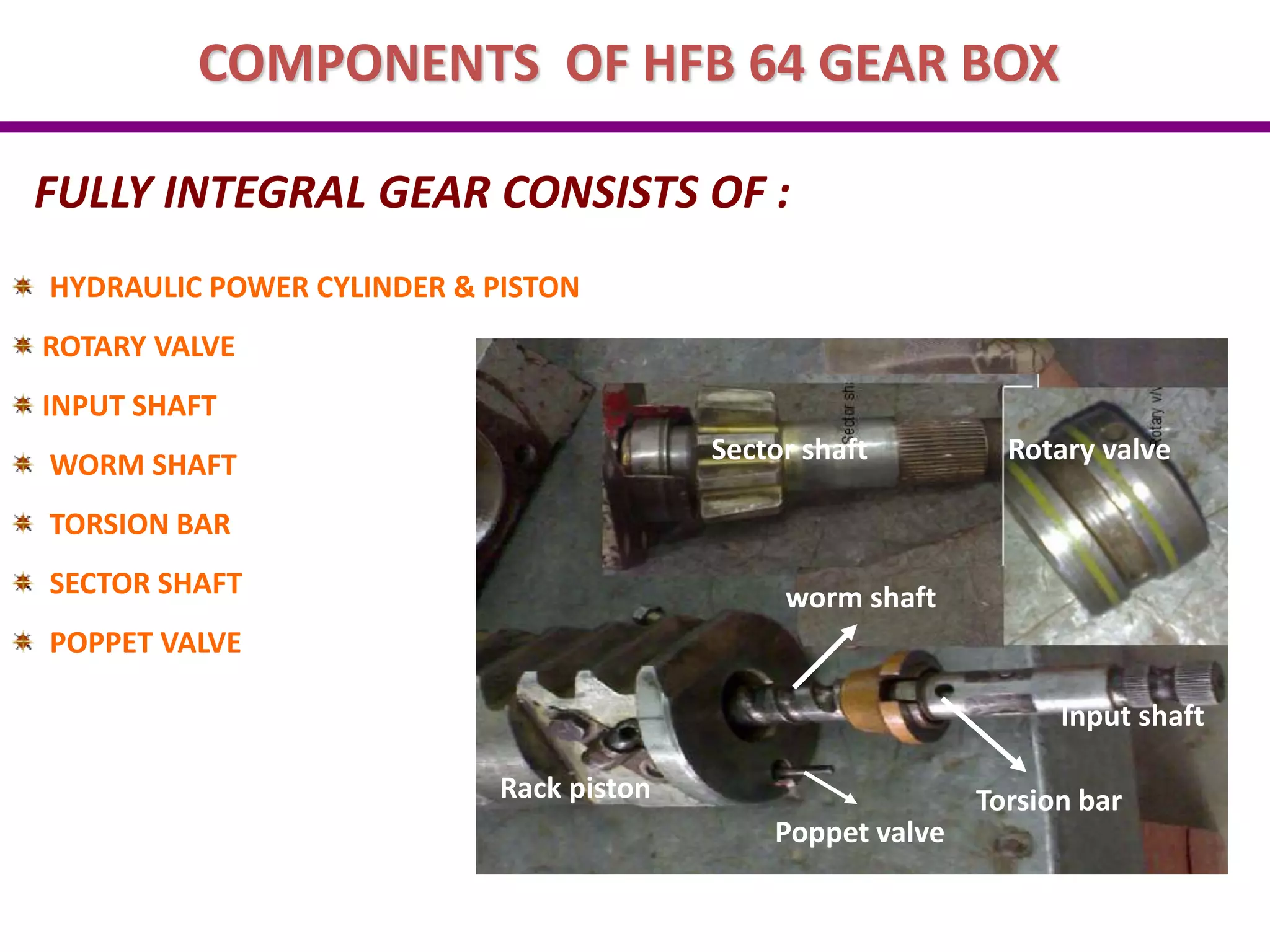
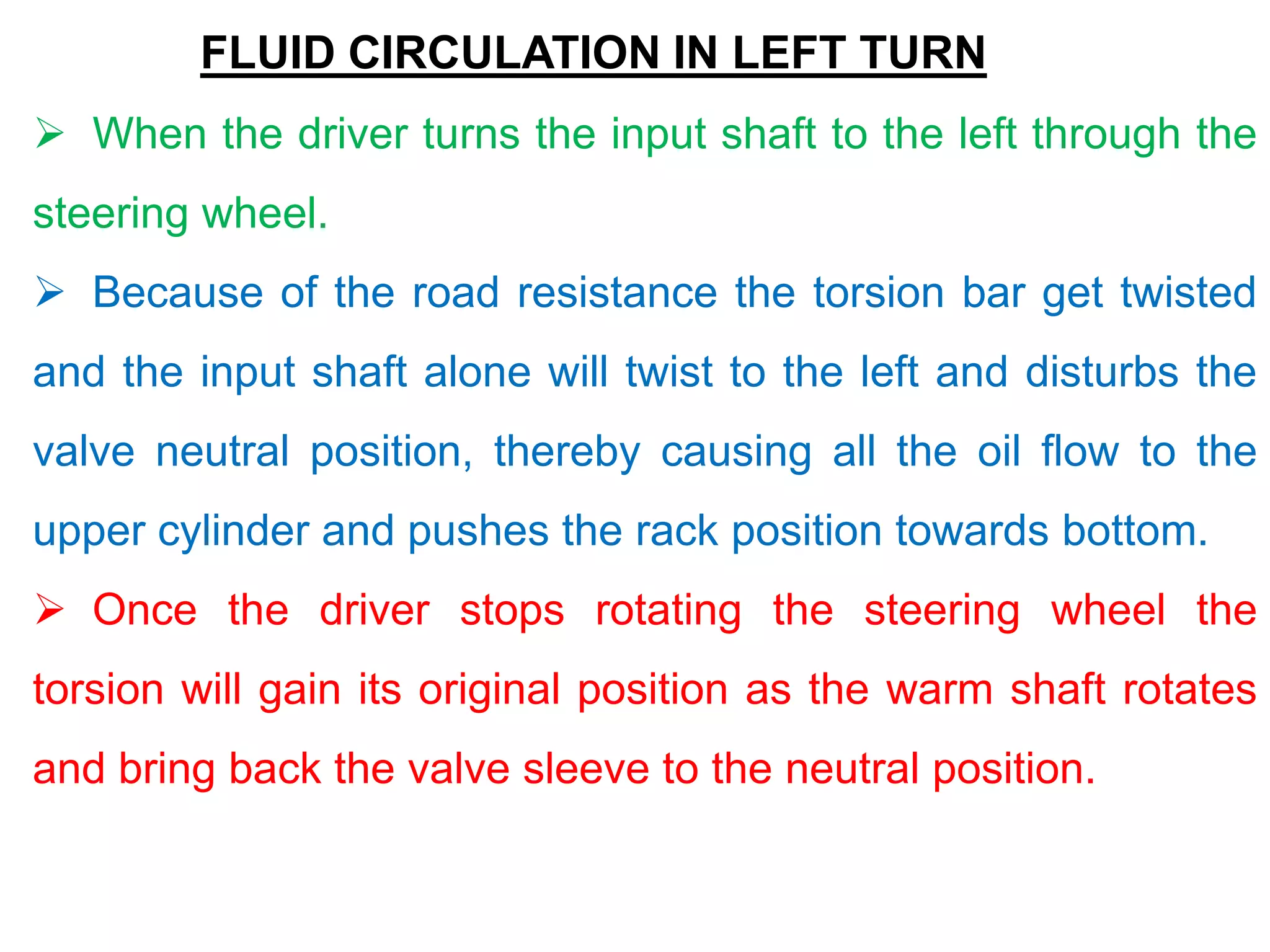
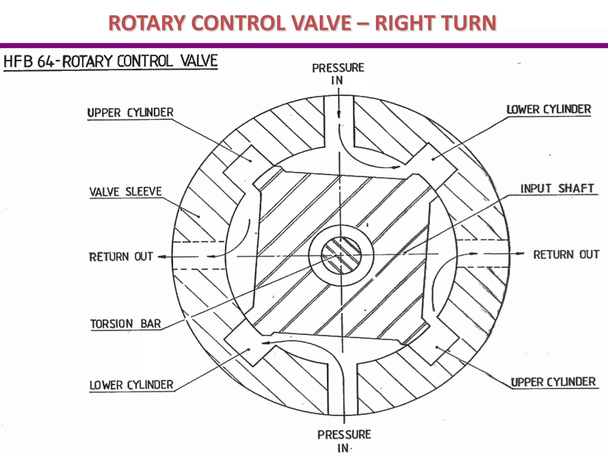
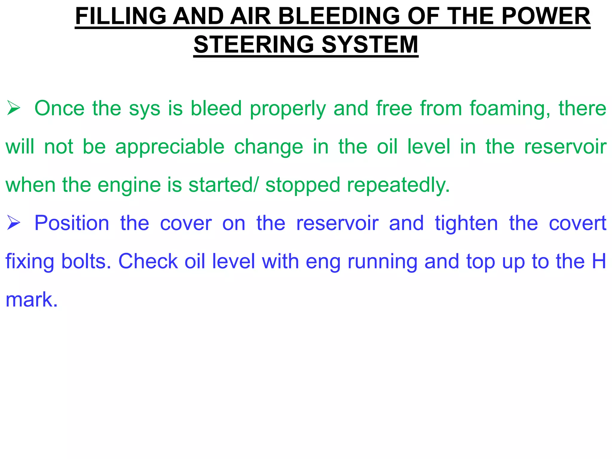
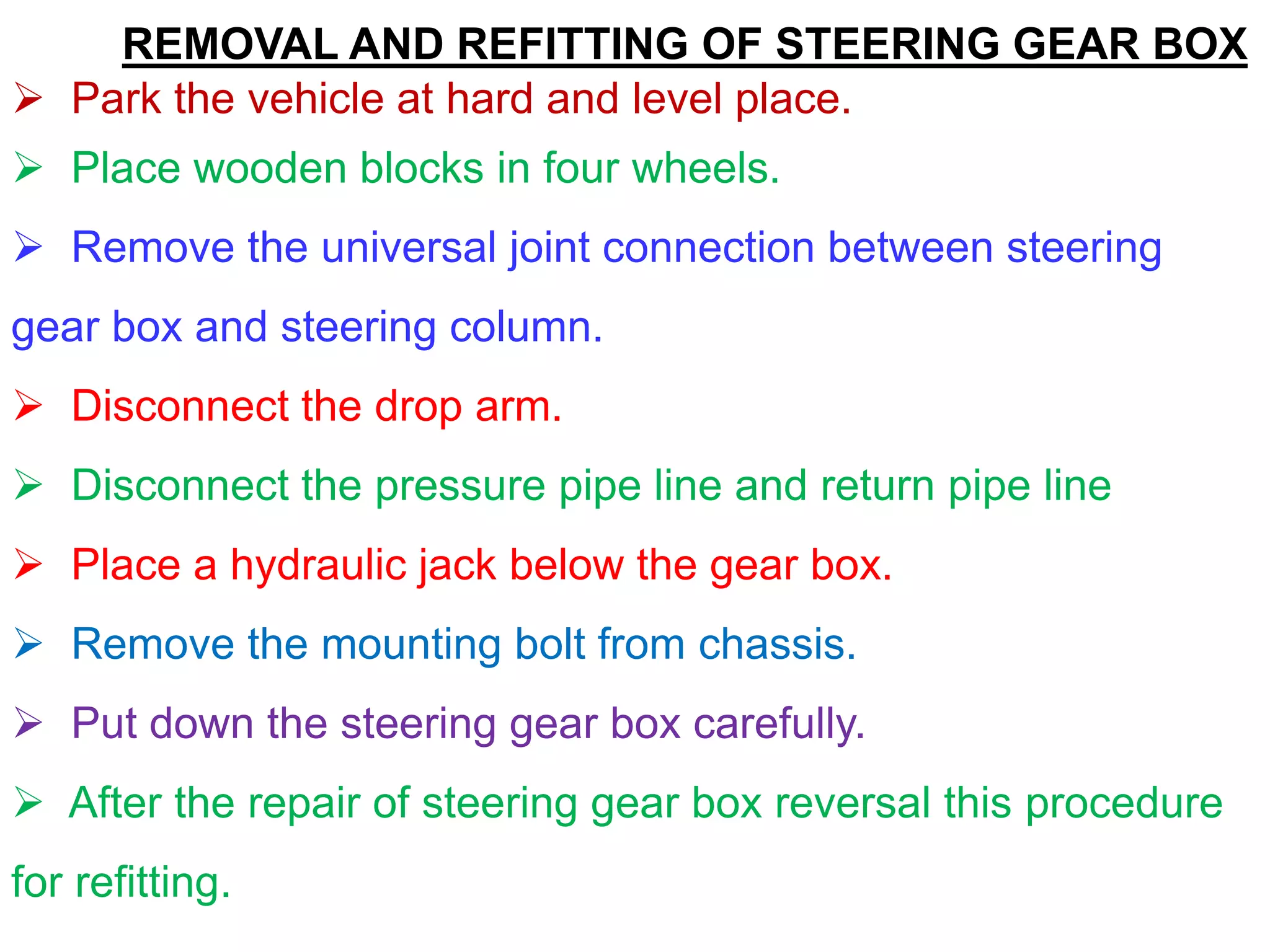
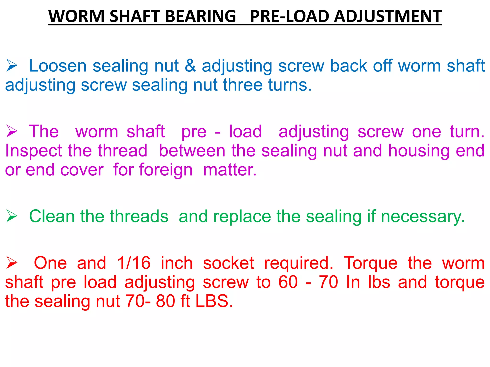
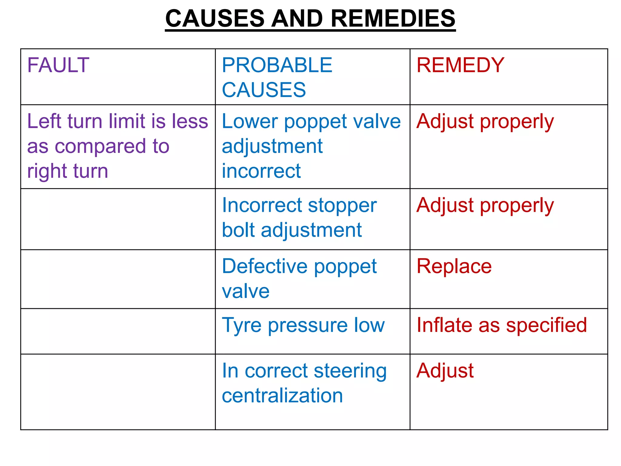
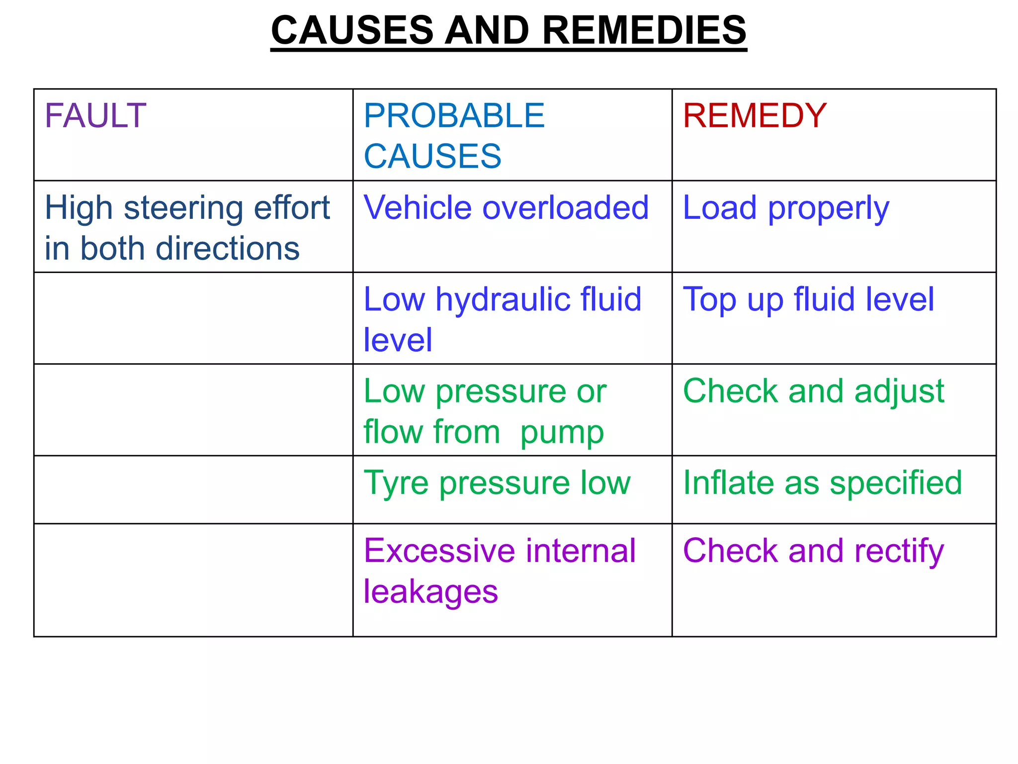
STEERING SYSTEM
INTRODUCTION TO STEERING SYSTEM
 It is the system which provides directional change in the
performance of an automobile.
 This system converts rotary movement of the steering
wheel into angular turn of the front wheels.
 It multiplies driver's effort by mechanical advantage enabling
him to turn the wheels.
QUALITIES OF POWER STEERING
 It must be capable of keeping the wheels, at all times, in true
rolling motion without rubbing or scuffing of tyres on road.
SYSTEM LAYOUT OF POWER STEERING
Power Steering
Pump Power Steering
FI Gearbox
Power Steering
Reservoir
Suction
Line
STEERING SYSTEM
QUALITIES OF POWER STEERING
 Steering in the system must be easily operatable.
 It should have a certain degree of self-cantering action to
keep the vehicle on a straight course.
DESCRIPTION OF POWER STEERING.
 Power steering is a steering in which external power is
utilized to assist operation of the system.
 It uses compressed air, electrical mechanism and hydraulic
pressure.
 It is actually power assisted steering in which a booster
arrangement is set in operation, when the steering wheel is
turned.
STEERING SYSTEM
TECH DATA
 MAKE : RANE POWER STEERING LTD
 TYPE : INTEGRAL POWER STG
 RATIO : 20.4:1
 SYSTEM PRESSURE : 138 KG/CM²
 OIL CAPACITY : 4 LTR
 STEERING WHEEL DIA : 500 MM
 LOCATION : RH
 TOE- IN : PARALLEL
 PUMP OUTPUT : 12 LTR/MIN
DESCRIPTION OF POWER STEERING
 The booster then takes over and does most of the steering
work.
 Power steering is of the two main classes which are as
follows.
ZF POWER STEERING
 It is that type of power steering in which power operating
assembly or booster assembly is built into the steering gear unit.
 In one form, the booster assembly is integrated with
recalculating ball steering gear and consists of two units ‘power
cylinder unit’ and ‘valve unit’.
 The power cylinder contains a piston which is connected to a
rack that operates a sector on the drop arm shaft.
ZF POWER STEERING
 The valve unit contains a spool in the housing which slides
up and down due to turning effect of steering wheel, admitting
fluid pressure to act on one or the other side of the piston.
 The pressure in the cylinder causes the piston to move,
resulting in the movement of sector shaft which turns the drop
arm for turning the wheel.
HFB 64 INTEGRAL HYDRAULIC POWER STEERING GEAR
 This steering gear was specifically designed for motor trucks,
new design features and our design experience with previous
models of integral hydraulic power steering gears have been
combined into this new product
HFB 64 Integral Hydraulic Power Steering Gear
ADDITIONAL FITMENTS OF POWER STEERING
Balanced Area Cyl. Back pressures cannot affect steering
stability.
High Temperature Seals. These specially developed seals
may be operated intermittently at 3000 F (148.90 C).
Manual Steering Capability. Provides for steering control in
the event of hydraulic failure.
Compactness. Lowest weight to output torque ratio in the
industry.
Auxiliary Porting Available. For auxiliary cyl control.
Seal Protectors. Provides protection from harsh environment.
RANE POWER STEERING SYSTEM
INTRODUCTION RANE POWER STEERING
ALS vehicle is fitted with Rane HFB64 Integral hydraulic
power steering system which is specially designed for motor
trucks
INTEGRAL POWER STEERING
 The HFB64 power steering gear box is the latest designed in
the family of integral hydraulic power steering gears.
 Integral hydraulic power steering means that the gear box
contains a manual steering mechanism .
 A hydraulic control valve and a hydraulic power cylinder all in
a single and compact package.
COMPONENTS OF HFB 64 GEAR BOX
FULLY INTEGRAL GEAR CONSISTS OF :
HYDRAULIC POWER CYLINDER & PISTON
ROTARY VALVE
INPUT SHAFT
WORM SHAFT
TORSION BAR
SECTOR SHAFT
POPPET VALVE
Sector shaft Rotary valve
Input shaft
worm shaft
Torsion bar
Rack piston
Poppet valve
HFB 64 GEAR BOX
FUNCTION OF HFB 64 GEAR OPERATION
 When the driver turns the steering wheel, he
activates the steering gear input shaft.
 A torsion bar pinned at its one end to the input shaft
and the other end to the worm shaft, turns with the
input shaft and exerts a rotational force on the worm
shaft.
 In response to this rotational force the worm shaft
acting through the re-circulating ball mechanism, tries
to move the rack piston axially through the gear
housing cylinder bore.
FUNTION OF HFB 64 GEAR OPERATION
 The rack piston’s axial movement is resisted by its
engagement
 To the sector shaft, which is connected by linkage to the
steered wheels.
 Because of this resistance, the torsion bar is twisted by the
input shaft, thereby actuating the control valve.
 Pressurized fluid directed by the control valve assists in
moving the rack piston axially through the cylinder bore.
 The rack piston then turns the sector shaft to steer the
vehicle.
FLUID CIRCULATION IN NORMAL POSITION
 The rotary control valve mechanism, which is the heart of
power steering system comprises of input shaft, warm shaft,
torsion bar and valve sleeve,.
 The input shaft as four lands and the valve sleeve has four
pockets assembled in neutral condition.
 The valve sleeve keyed connection with assembled in neutral
condition.
 The valve sleeve keyed connection with the warm shaft.
Always the valves will be in the neutral position.
 In this condition the oil flows to the both sides of the cylinder
and return back to the reservoir.
ROTARY CONTROL VALVE - NEUTRAL
FLUID CIRCULATION IN LEFT TURN
 When the driver turns the input shaft to the left through the
steering wheel.
 Because of the road resistance the torsion bar get twisted
and the input shaft alone will twist to the left and disturbs the
valve neutral position, thereby causing all the oil flow to the
upper cylinder and pushes the rack position towards bottom.
 Once the driver stops rotating the steering wheel the
torsion will gain its original position as the warm shaft rotates
and bring back the valve sleeve to the neutral position.
POWER STEERING SYSTEM : LEFT TURN
ROTARY CONTROL VALVE – LEFT TURN
FLUID CIRCULATION IN RIGHT TURN
 When the driver turns the input shaft to the right through
the steering wheel.
 Because of the road resistance the torsion bar get twisted
and the input shaft alone will twist to the right and disturbs the
valve neutral position, thereby causing all the oil flow to the
lower cylinder and pushes the rack position towards top.
 Once the driver stops rotating the stg wheel the torsion will
gain its original position as the warm shaft rotates bring back
the valve sleeve to the neutral position.
ROTARY CONTROL VALVE – RIGHT TURN
STUDY OF PIPE LINES
There are three pipe lines in the power steering
system.
 Suction line : Suction line is fitted between fluid reservoir
and vane pump. Its diameter is more than other pipe lines.
 Pressure line : Pressure pipe line is fitted between vane
pump and steering gear box. Initially pressure built up in this
line.
 Return line : Return line is fitted between steering gear
box and fluid reservoir. The fluid filter is provided in last end
in this line. The fluid return from the steering gear box to fluid
reservoir through this pipe line.
STUDY OF FLUID RESERVOIR
 Fluid reservoir is located rear side of the cabin. It contains
a 10 Micron filter, filler cap and a dip stick.
 The dipstick has min and max mark, fill the fluid according
to the mark.
 There is a seal in the cap of reservoir to seal the leakage
of the fluid.
 Fluid container stores the steering oil.
 A dust cover is provided for protection from the dust
particles.
OIL CHANGING PROCEDURE
 The steering oil should be change after the specific
periodicity or requirement of the system.
 Jack up both the front wheels in parallel condition.
 Disconnect the returning line of steering gear box and
collect the used oil in the container.
 Turn the steering wheel left/right several times until the
system is empty.
 Connect the pipe line and fill the oil in the reservoir.
FILLING AND AIR BLEEDING OF THE POWER
STEERING SYSTEM
 Fill the reservoir nearly full crank the engine for 10 seconds
without, if possible, allowing it to start.
 If the engine does start shut it off immediately. Check and
refill the reservoir. Repeat at least three times, each time
checking and refilling the reservoir.
 Start the engine and let it idle for 2 minutes shut the engine
off and check the fluid level in the reservoir
 Start the eng again. Stg the veh from full left to full RT sev-
eral times. Add fluid as necessary, up to H mark on the dipstick.
FILLING AND AIR BLEEDING OF THE POWER
STEERING SYSTEM
 Start the eng and let it idle for 2 min. With the eng at the
steady speed, check for bubble/foaming in the oil. If present, it
indicates that air is getting sucked into the system.
Check the suction level/ fitting/the pump shaft seal area and
correct, if necessary.
 Start the engine again and steer the wheel from full right to
full lefts turns several times. Add fluid , as necessary.
 The above procedure should remove all air from the steering
system.
FILLING AND AIR BLEEDING OF THE POWER
STEERING SYSTEM
 Once the sys is bleed properly and free from foaming, there
will not be appreciable change in the oil level in the reservoir
when the engine is started/ stopped repeatedly.
 Position the cover on the reservoir and tighten the covert
fixing bolts. Check oil level with eng running and top up to the H
mark.
REMOVAL AND REFITTING OF STEERING GEAR BOX
 Park the vehicle at hard and level place.
 Place wooden blocks in four wheels.
 Remove the universal joint connection between steering
gear box and steering column.
 Disconnect the drop arm.
 Disconnect the pressure pipe line and return pipe line
 Place a hydraulic jack below the gear box.
 Remove the mounting bolt from chassis.
 Put down the steering gear box carefully.
 After the repair of steering gear box reversal this procedure
for refitting.
FUNCTION OF POPPET VALVES
FUNCTION OF POPPETS
HFB 64 gears are equipped with two unloading valves, one
at each end of the rack piston. One valve or the other depending
on the direction of turn will trip as the steered wheels approach
the axle stops (which must be set according to manufacturers
specification).
ADJUSTMENT OF STEERING GEAR BOX
There are there adjustment in the steering gear box.
WORM SHAFT BEARING PRE-LOAD ADJUSTMENT
 Loosen sealing nut & adjusting screw back off worm shaft
adjusting screw sealing nut three turns.
 The worm shaft pre - load adjusting screw one turn.
Inspect the thread between the sealing nut and housing end
or end cover for foreign matter.
 Clean the threads and replace the sealing if necessary.
 One and 1/16 inch socket required. Torque the worm
shaft pre load adjusting screw to 60 - 70 In lbs and torque
the sealing nut 70- 80 ft LBS.
SECTOR SHAFT BACK LASH ADJUSTMENT
 Sector shaft adjusting screw is accessible remove the drag
link from pitman arm.
 Loosen jam nut with a 3/4 inch socket and move the
adjusting screw clockwise until the sector shaft and rack piston
are in contact (use not more than 10ft lbs of torque ) then turn
the adjusting screw counter clockwise one turn.
 At this point there should be lash at the pitman arm. To
adjust slowly turn the adjusting screw clockwise until no lash is
felt at the pitman arm.
 Hold the adjusting screw in place and tighten the jam nut.
Final torque 40 -45 ft lbs.
POPPET VALVE ADJUSTMENT
SET AXLE STOP
Before you adjust the poppet valve set the axle stops
according to the manufacture's specifications.
INSTALL FLOW METER
Install a pressure gauge or a flow meter or
pressure gauge package into the supply line from the pump
to the gear . make sure that flow meter can be pressurized.
Bring the fluid temperature to between 125ºf and 135ºf Using
the method to warm the system up described in the troubling
shooting section.
FAULT PROBABLE
CAUSES
REMEDY
Left turn limit is less
as compared to
right turn
Lower poppet valve
adjustment
incorrect
Adjust properly
Incorrect stopper
bolt adjustment
Adjust properly
Defective poppet
valve
Replace
Tyre pressure low Inflate as specified
In correct steering
centralization
Adjust
CAUSES AND REMEDIES
FAULT PROBABLE
CAUSES
REMEDY
High steering effort
in both directions
Vehicle overloaded Load properly
Low hydraulic fluid
level
Top up fluid level
Low pressure or
flow from pump
Check and adjust
Tyre pressure low Inflate as specified
Excessive internal
leakages
Check and rectify
CAUSES AND REMEDIES

STEERING SYSTEM.pptx

  • 1.
    STEERING SYSTEM INTRODUCTION TOSTEERING SYSTEM  It is the system which provides directional change in the performance of an automobile.  This system converts rotary movement of the steering wheel into angular turn of the front wheels.  It multiplies driver's effort by mechanical advantage enabling him to turn the wheels. QUALITIES OF POWER STEERING  It must be capable of keeping the wheels, at all times, in true rolling motion without rubbing or scuffing of tyres on road.
  • 2.
    SYSTEM LAYOUT OFPOWER STEERING Power Steering Pump Power Steering FI Gearbox Power Steering Reservoir Suction Line
  • 3.
    STEERING SYSTEM QUALITIES OFPOWER STEERING  Steering in the system must be easily operatable.  It should have a certain degree of self-cantering action to keep the vehicle on a straight course. DESCRIPTION OF POWER STEERING.  Power steering is a steering in which external power is utilized to assist operation of the system.  It uses compressed air, electrical mechanism and hydraulic pressure.  It is actually power assisted steering in which a booster arrangement is set in operation, when the steering wheel is turned.
  • 4.
    STEERING SYSTEM TECH DATA MAKE : RANE POWER STEERING LTD  TYPE : INTEGRAL POWER STG  RATIO : 20.4:1  SYSTEM PRESSURE : 138 KG/CM²  OIL CAPACITY : 4 LTR  STEERING WHEEL DIA : 500 MM  LOCATION : RH  TOE- IN : PARALLEL  PUMP OUTPUT : 12 LTR/MIN
  • 5.
    DESCRIPTION OF POWERSTEERING  The booster then takes over and does most of the steering work.  Power steering is of the two main classes which are as follows. ZF POWER STEERING  It is that type of power steering in which power operating assembly or booster assembly is built into the steering gear unit.  In one form, the booster assembly is integrated with recalculating ball steering gear and consists of two units ‘power cylinder unit’ and ‘valve unit’.  The power cylinder contains a piston which is connected to a rack that operates a sector on the drop arm shaft.
  • 6.
    ZF POWER STEERING The valve unit contains a spool in the housing which slides up and down due to turning effect of steering wheel, admitting fluid pressure to act on one or the other side of the piston.  The pressure in the cylinder causes the piston to move, resulting in the movement of sector shaft which turns the drop arm for turning the wheel. HFB 64 INTEGRAL HYDRAULIC POWER STEERING GEAR  This steering gear was specifically designed for motor trucks, new design features and our design experience with previous models of integral hydraulic power steering gears have been combined into this new product
  • 7.
    HFB 64 IntegralHydraulic Power Steering Gear
  • 8.
    ADDITIONAL FITMENTS OFPOWER STEERING Balanced Area Cyl. Back pressures cannot affect steering stability. High Temperature Seals. These specially developed seals may be operated intermittently at 3000 F (148.90 C). Manual Steering Capability. Provides for steering control in the event of hydraulic failure. Compactness. Lowest weight to output torque ratio in the industry. Auxiliary Porting Available. For auxiliary cyl control. Seal Protectors. Provides protection from harsh environment.
  • 9.
    RANE POWER STEERINGSYSTEM INTRODUCTION RANE POWER STEERING ALS vehicle is fitted with Rane HFB64 Integral hydraulic power steering system which is specially designed for motor trucks INTEGRAL POWER STEERING  The HFB64 power steering gear box is the latest designed in the family of integral hydraulic power steering gears.  Integral hydraulic power steering means that the gear box contains a manual steering mechanism .  A hydraulic control valve and a hydraulic power cylinder all in a single and compact package.
  • 10.
    COMPONENTS OF HFB64 GEAR BOX FULLY INTEGRAL GEAR CONSISTS OF : HYDRAULIC POWER CYLINDER & PISTON ROTARY VALVE INPUT SHAFT WORM SHAFT TORSION BAR SECTOR SHAFT POPPET VALVE Sector shaft Rotary valve Input shaft worm shaft Torsion bar Rack piston Poppet valve
  • 11.
  • 12.
    FUNCTION OF HFB64 GEAR OPERATION  When the driver turns the steering wheel, he activates the steering gear input shaft.  A torsion bar pinned at its one end to the input shaft and the other end to the worm shaft, turns with the input shaft and exerts a rotational force on the worm shaft.  In response to this rotational force the worm shaft acting through the re-circulating ball mechanism, tries to move the rack piston axially through the gear housing cylinder bore.
  • 13.
    FUNTION OF HFB64 GEAR OPERATION  The rack piston’s axial movement is resisted by its engagement  To the sector shaft, which is connected by linkage to the steered wheels.  Because of this resistance, the torsion bar is twisted by the input shaft, thereby actuating the control valve.  Pressurized fluid directed by the control valve assists in moving the rack piston axially through the cylinder bore.  The rack piston then turns the sector shaft to steer the vehicle.
  • 14.
    FLUID CIRCULATION INNORMAL POSITION  The rotary control valve mechanism, which is the heart of power steering system comprises of input shaft, warm shaft, torsion bar and valve sleeve,.  The input shaft as four lands and the valve sleeve has four pockets assembled in neutral condition.  The valve sleeve keyed connection with assembled in neutral condition.  The valve sleeve keyed connection with the warm shaft. Always the valves will be in the neutral position.  In this condition the oil flows to the both sides of the cylinder and return back to the reservoir.
  • 16.
  • 17.
    FLUID CIRCULATION INLEFT TURN  When the driver turns the input shaft to the left through the steering wheel.  Because of the road resistance the torsion bar get twisted and the input shaft alone will twist to the left and disturbs the valve neutral position, thereby causing all the oil flow to the upper cylinder and pushes the rack position towards bottom.  Once the driver stops rotating the steering wheel the torsion will gain its original position as the warm shaft rotates and bring back the valve sleeve to the neutral position.
  • 18.
  • 19.
    ROTARY CONTROL VALVE– LEFT TURN
  • 20.
    FLUID CIRCULATION INRIGHT TURN  When the driver turns the input shaft to the right through the steering wheel.  Because of the road resistance the torsion bar get twisted and the input shaft alone will twist to the right and disturbs the valve neutral position, thereby causing all the oil flow to the lower cylinder and pushes the rack position towards top.  Once the driver stops rotating the stg wheel the torsion will gain its original position as the warm shaft rotates bring back the valve sleeve to the neutral position.
  • 22.
    ROTARY CONTROL VALVE– RIGHT TURN
  • 23.
    STUDY OF PIPELINES There are three pipe lines in the power steering system.  Suction line : Suction line is fitted between fluid reservoir and vane pump. Its diameter is more than other pipe lines.  Pressure line : Pressure pipe line is fitted between vane pump and steering gear box. Initially pressure built up in this line.  Return line : Return line is fitted between steering gear box and fluid reservoir. The fluid filter is provided in last end in this line. The fluid return from the steering gear box to fluid reservoir through this pipe line.
  • 24.
    STUDY OF FLUIDRESERVOIR  Fluid reservoir is located rear side of the cabin. It contains a 10 Micron filter, filler cap and a dip stick.  The dipstick has min and max mark, fill the fluid according to the mark.  There is a seal in the cap of reservoir to seal the leakage of the fluid.  Fluid container stores the steering oil.  A dust cover is provided for protection from the dust particles.
  • 25.
    OIL CHANGING PROCEDURE The steering oil should be change after the specific periodicity or requirement of the system.  Jack up both the front wheels in parallel condition.  Disconnect the returning line of steering gear box and collect the used oil in the container.  Turn the steering wheel left/right several times until the system is empty.  Connect the pipe line and fill the oil in the reservoir.
  • 26.
    FILLING AND AIRBLEEDING OF THE POWER STEERING SYSTEM  Fill the reservoir nearly full crank the engine for 10 seconds without, if possible, allowing it to start.  If the engine does start shut it off immediately. Check and refill the reservoir. Repeat at least three times, each time checking and refilling the reservoir.  Start the engine and let it idle for 2 minutes shut the engine off and check the fluid level in the reservoir  Start the eng again. Stg the veh from full left to full RT sev- eral times. Add fluid as necessary, up to H mark on the dipstick.
  • 27.
    FILLING AND AIRBLEEDING OF THE POWER STEERING SYSTEM  Start the eng and let it idle for 2 min. With the eng at the steady speed, check for bubble/foaming in the oil. If present, it indicates that air is getting sucked into the system. Check the suction level/ fitting/the pump shaft seal area and correct, if necessary.  Start the engine again and steer the wheel from full right to full lefts turns several times. Add fluid , as necessary.  The above procedure should remove all air from the steering system.
  • 28.
    FILLING AND AIRBLEEDING OF THE POWER STEERING SYSTEM  Once the sys is bleed properly and free from foaming, there will not be appreciable change in the oil level in the reservoir when the engine is started/ stopped repeatedly.  Position the cover on the reservoir and tighten the covert fixing bolts. Check oil level with eng running and top up to the H mark.
  • 29.
    REMOVAL AND REFITTINGOF STEERING GEAR BOX  Park the vehicle at hard and level place.  Place wooden blocks in four wheels.  Remove the universal joint connection between steering gear box and steering column.  Disconnect the drop arm.  Disconnect the pressure pipe line and return pipe line  Place a hydraulic jack below the gear box.  Remove the mounting bolt from chassis.  Put down the steering gear box carefully.  After the repair of steering gear box reversal this procedure for refitting.
  • 30.
    FUNCTION OF POPPETVALVES FUNCTION OF POPPETS HFB 64 gears are equipped with two unloading valves, one at each end of the rack piston. One valve or the other depending on the direction of turn will trip as the steered wheels approach the axle stops (which must be set according to manufacturers specification). ADJUSTMENT OF STEERING GEAR BOX There are there adjustment in the steering gear box.
  • 31.
    WORM SHAFT BEARINGPRE-LOAD ADJUSTMENT  Loosen sealing nut & adjusting screw back off worm shaft adjusting screw sealing nut three turns.  The worm shaft pre - load adjusting screw one turn. Inspect the thread between the sealing nut and housing end or end cover for foreign matter.  Clean the threads and replace the sealing if necessary.  One and 1/16 inch socket required. Torque the worm shaft pre load adjusting screw to 60 - 70 In lbs and torque the sealing nut 70- 80 ft LBS.
  • 32.
    SECTOR SHAFT BACKLASH ADJUSTMENT  Sector shaft adjusting screw is accessible remove the drag link from pitman arm.  Loosen jam nut with a 3/4 inch socket and move the adjusting screw clockwise until the sector shaft and rack piston are in contact (use not more than 10ft lbs of torque ) then turn the adjusting screw counter clockwise one turn.  At this point there should be lash at the pitman arm. To adjust slowly turn the adjusting screw clockwise until no lash is felt at the pitman arm.  Hold the adjusting screw in place and tighten the jam nut. Final torque 40 -45 ft lbs.
  • 33.
    POPPET VALVE ADJUSTMENT SETAXLE STOP Before you adjust the poppet valve set the axle stops according to the manufacture's specifications. INSTALL FLOW METER Install a pressure gauge or a flow meter or pressure gauge package into the supply line from the pump to the gear . make sure that flow meter can be pressurized. Bring the fluid temperature to between 125ºf and 135ºf Using the method to warm the system up described in the troubling shooting section.
  • 35.
    FAULT PROBABLE CAUSES REMEDY Left turnlimit is less as compared to right turn Lower poppet valve adjustment incorrect Adjust properly Incorrect stopper bolt adjustment Adjust properly Defective poppet valve Replace Tyre pressure low Inflate as specified In correct steering centralization Adjust CAUSES AND REMEDIES
  • 36.
    FAULT PROBABLE CAUSES REMEDY High steeringeffort in both directions Vehicle overloaded Load properly Low hydraulic fluid level Top up fluid level Low pressure or flow from pump Check and adjust Tyre pressure low Inflate as specified Excessive internal leakages Check and rectify CAUSES AND REMEDIES