Downloaded 312 times
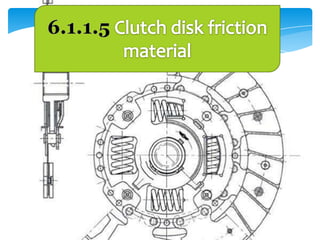
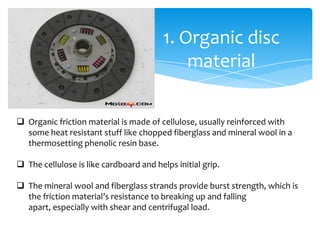


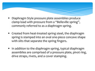


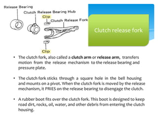


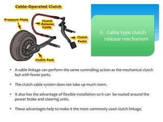


The document summarizes different types of clutch friction materials and components. It describes organic, heavy duty, semi-metallic, and copper ceramic discs, as well as carbon-carbon materials. It also discusses diaphragm style pressure plates, clutch release bearings and forks, and linkage, cable, and hydraulic clutch release mechanisms.