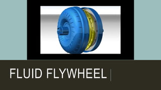
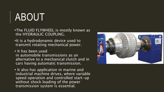
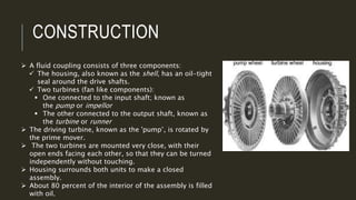
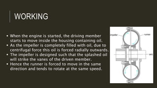
FLUID FLYWHEEL
ABOUT
The FLUID FLYWHEEL is mostly known as
the HYDRAULIC COUPLING.
It is a hydrodynamic device used to
transmit rotating mechanical power.
 It has been used
in automobile transmissions as an
alternative to a mechanical clutch and in
cars having automatic transmission.
 It also has application in marine and
industrial machine drives, where variable
speed operation and controlled start-up
without shock loading of the power
transmission system is essential.
CONSTRUCTION
 A fluid coupling consists of three components:
 The housing, also known as the shell, has an oil-tight
seal around the drive shafts.
 Two turbines (fan like components):
 One connected to the input shaft; known as
the pump or impellor
 The other connected to the output shaft, known as
the turbine or runner
 The driving turbine, known as the 'pump’, is rotated by
the prime mover.
 The two turbines are mounted very close, with their
open ends facing each other, so that they can be turned
independently without touching.
 Housing surrounds both units to make a closed
assembly.
 About 80 percent of the interior of the assembly is filled
with oil.
WORKING
 When the engine is started, the driving member
starts to move inside the housing containing oil.
 As the impeller is completely filled with oil, due to
centrifugal force this oil is forced radially outwards.
 The impeller is designed such that the splashed oil
will strike the vanes of the driven member.
 Hence the runner is forced to move in the same
direction and tends to rotate at the same speed.
HYDRAULIC FLUID
As a fluid coupling operates kinetically. Thus, low viscosity fluids are
preferred.
Generally multi-grade motor oils or automatic transmission fluids are
used. Increasing density of the fluid increases the amount
of torque that can be transmitted at a given input speed.
 However, hydraulic fluids, much like other fluids, are subject to
changes in viscosity with temperature change. This leads to a change
in transmission performance.
So for constant efficiency, a motor oil or automatic transmission fluid
with a high viscosity index should be used.
CHARACTERISTICS OF A FLUID
FLYWHEEL
Stall speed
The stall speed is defined as the highest speed at which the pump can turn
when the output turbine is locked and maximum input power is applied.
Under stall conditions all of the engine's power would be dissipated in the
fluid coupling as heat, possibly leading to damage.
Slip
The runner speed is almost equal to that of the impeller only when the
efficiency of liquid coupling is highest. But usually the runner speed is less
than that of the impeller. The (speed) lag of the runner behind the impeller is
known as slip. This (speed) slip varies with many factors such as engine
speed, vehicle speed and engine and vehicle load.
Slip is given as (N1-N2)/N1 where N1,N2 are speed of driving and driven
ADVANTAGES
An ordinary friction clutch would be damaged by prolonged
slipping. But by prolonged slipping, the fluid flywheel will not
suffer any mechanical damage.
When a liquid coupling is used with a conventional clutch and
transmission, it enables the driver to use the clutch and gears
with less skill and fatigue than with an all mechanical linkage.
Unskilful clutch engagement or selection of the improper gear
will not produce any chattering and bucking.
Any sudden load is cushioned and absorbed by the coupling
so that dynamic stresses on the gear teeth of the transmission
are greatly reduced.
THANK
YOU

Fluid flywheel

  • 1.
  • 2.
    ABOUT The FLUID FLYWHEELis mostly known as the HYDRAULIC COUPLING. It is a hydrodynamic device used to transmit rotating mechanical power.  It has been used in automobile transmissions as an alternative to a mechanical clutch and in cars having automatic transmission.  It also has application in marine and industrial machine drives, where variable speed operation and controlled start-up without shock loading of the power transmission system is essential.
  • 3.
    CONSTRUCTION  A fluidcoupling consists of three components:  The housing, also known as the shell, has an oil-tight seal around the drive shafts.  Two turbines (fan like components):  One connected to the input shaft; known as the pump or impellor  The other connected to the output shaft, known as the turbine or runner  The driving turbine, known as the 'pump’, is rotated by the prime mover.  The two turbines are mounted very close, with their open ends facing each other, so that they can be turned independently without touching.  Housing surrounds both units to make a closed assembly.  About 80 percent of the interior of the assembly is filled with oil.
  • 4.
    WORKING  When theengine is started, the driving member starts to move inside the housing containing oil.  As the impeller is completely filled with oil, due to centrifugal force this oil is forced radially outwards.  The impeller is designed such that the splashed oil will strike the vanes of the driven member.  Hence the runner is forced to move in the same direction and tends to rotate at the same speed.
  • 7.
    HYDRAULIC FLUID As afluid coupling operates kinetically. Thus, low viscosity fluids are preferred. Generally multi-grade motor oils or automatic transmission fluids are used. Increasing density of the fluid increases the amount of torque that can be transmitted at a given input speed.  However, hydraulic fluids, much like other fluids, are subject to changes in viscosity with temperature change. This leads to a change in transmission performance. So for constant efficiency, a motor oil or automatic transmission fluid with a high viscosity index should be used.
  • 8.
    CHARACTERISTICS OF AFLUID FLYWHEEL Stall speed The stall speed is defined as the highest speed at which the pump can turn when the output turbine is locked and maximum input power is applied. Under stall conditions all of the engine's power would be dissipated in the fluid coupling as heat, possibly leading to damage. Slip The runner speed is almost equal to that of the impeller only when the efficiency of liquid coupling is highest. But usually the runner speed is less than that of the impeller. The (speed) lag of the runner behind the impeller is known as slip. This (speed) slip varies with many factors such as engine speed, vehicle speed and engine and vehicle load. Slip is given as (N1-N2)/N1 where N1,N2 are speed of driving and driven
  • 9.
    ADVANTAGES An ordinary frictionclutch would be damaged by prolonged slipping. But by prolonged slipping, the fluid flywheel will not suffer any mechanical damage. When a liquid coupling is used with a conventional clutch and transmission, it enables the driver to use the clutch and gears with less skill and fatigue than with an all mechanical linkage. Unskilful clutch engagement or selection of the improper gear will not produce any chattering and bucking. Any sudden load is cushioned and absorbed by the coupling so that dynamic stresses on the gear teeth of the transmission are greatly reduced.
  • 10.