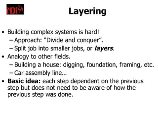
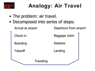
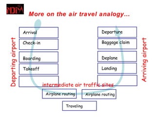
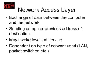
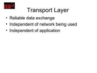
Downloaded 123 times


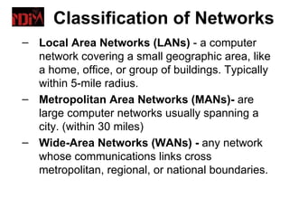
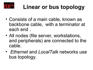
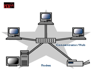


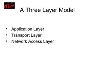

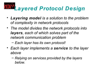
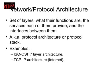
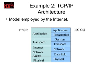
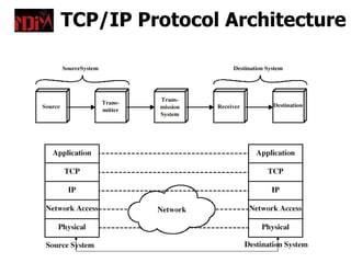

A computer network connects two or more computers together to allow sharing of resources and communication between users. Common network types include local area networks (LANs) within a building, metropolitan area networks (MANs) within a city, and wide area networks (WANs) spanning multiple cities or countries. The topology, or layout of connections between devices, can take bus, star, ring or mesh forms. Protocols and layered network architectures like TCP/IP or OSI model provide standards for communication between networked devices.


![Unit2[1]](https://cdn.slidesharecdn.com/ss_thumbnails/unit21-090714220554-phpapp02-thumbnail.jpg?width=640&height=640&fit=bounds)
![Unit2[1]](https://cdn.slidesharecdn.com/ss_thumbnails/unit21-090714220605-phpapp02-thumbnail.jpg?width=640&height=640&fit=bounds)


