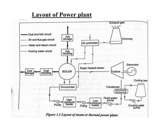
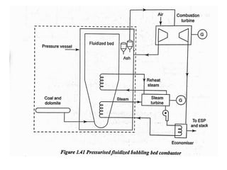
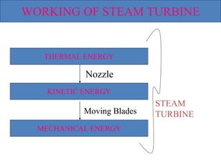
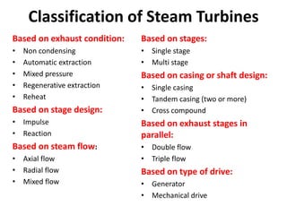
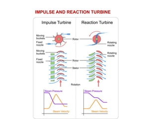
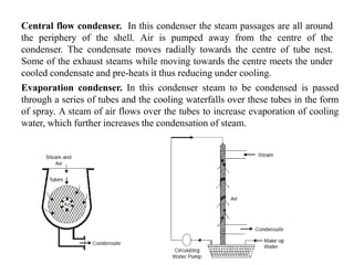
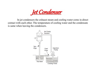
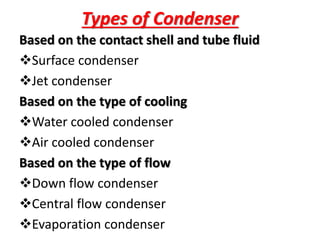
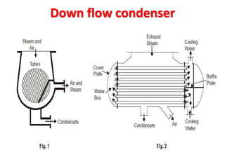
20ME701
POWER
PLANT
ENGINEERIN
G
UNIT I STEAM POWER PLANT
Layout of modern coal power plant, super critical
boilers, FBC boilers, coal handling, pulveriser, ash
handling and types of draught – surface condenser
types – cooling towers – binary cycles –
cogeneration system.
LOCATION OF POWER PLANT
Layout of Power plant
Coal and ash circuit
Air and flue gas circuit
Water and steam circuit
Cooling water circuit
BOILERS
Boilers
Boiler also known as steam generator is a
closed vessel in which steam is generated
from water by the application of heat and
pressure being higher than the
atmospheric
The main function of a boiler is to
evaporate water into steam at a higher
pressure
Requisites of a boiler
• A good boiler should be capable of
producing maximum amount of steam with
minimum initial cost
• It should be compact in size and safe in
working
• The components and parts should be easily
accessible for inspection and repair
• The heat produced by the fuel in the
furnace should be utilized maximum
Classification of
boilers
According to the flow of water and hot gases
Fire tube boilers – Ex Cochran, Lancashire
Water tube boilers- Ex Babcock, Wilcox boiler
According to the method of firing
Internally fired boilers – Ex Lancashire
Externally fired boilers - Ex Babcock, Wilcox boiler
According to the method of water circulation
Natural circulation boilers - Cochran, Lancashire
Forced circulation boilers – La-Mont , velox boiler
According to the pressure developed
Low pressure boilers - Ex Cochran, Lancashire
Medium pressure boilers-Ex Lancashire, Locomotive Boiler
High pressure boilers - Ex Babcock, Wilcox boiler
According to the axis of the shell
Vertical boilers – Cochran boiler
Inclined boilers
Horizontal boilers - Lancashire boiler , locomotive
boiler
According to the use of the boiler
Stationary boilers - Babcock, Wilcox boiler
Mobile boilers – locomotive boiler
La-Mont Boiler
Components
• Steam separator drum
• Water circulating pump
• Distributing header
• Evaporator
• Convection superheater
• Economiser
• Air preheater
• This working pressure of this boiler is above
170 bar and have the steam generation
capacity of about 50000 kg/hour at
temperature 773 K .
Economizer:
• Economizer use to preheat the water by using remaining
heat of the combustion gases. It increases
the boiler efficiency. The feed water first supplied to the
economizer before entering to the boiler.
Centrifugal pump:
• The Lamont boiler is a force convection boiler. So a
centrifugal pump is used to circulate water inside the
boiler. This pump is driven by a steam turbine. The
steam for the turbine is taken by the boiler.
Evaporator tube:
• The evaporator tube or can say water tubes are situated
at furnace wall which increase the heating surface of
boiler. This is also at the up side and down side of the
furnace and other equipment. The main function of
these tubes to evaporate water into steam. This also
cools down the furnace wall.
Grate:
• The space in the furnace where the fuel is burn is
called grate. It is bottom side of furnace.
Furnace:
• In the Lamont boiler vertical furnace is used. The
main function of Furnace is to burn the fuel.
Super heater:
• The steam generated by the evaporator tube is
saturated steam. If it directly used in steam
turbine can cause the corrosion. So the saturated
steam sends to the super heater where it can
increase the temperature of steam.
Water steam separator drum:
• The steam separator is situated outside from
the boiler. The mixture of water and steam
from the evaporator tube send to the steam
separator where it separate the steam and send
it to super heater. The remaining water again
sends to the economizer.
Air preheater:
• It’s main function to preheat air before
entering into furnace.
Advantages
1. It can high pressure boiler.
2. It is flexible in design.
3. This boiler can reassemble in natural circulation
boiler.
4. It can easily start.
5. It has high steam generation capacity of about
50 ton/ hour.
6. This boiler has higher heat transfer rate.
Benson Boiler
1. Air Preheater
It preheats the air before entering into the
furnace. The preheated air increases the burning
efficiency of the fuel.
2. Economiser
It heats the water to a certain temperature.
3. Radiant Superheater
It is superheater that heats the water with
radiation produced by the burnt fuel. It raises the
temperature to supercritical temperature.
4. Convection Evaporator
• It evaporates the superheated water and converts
them into steam. It does so by the convection mode
of heat transfer to the water from the hot flue gases.
5. Convection Superheater
• It superheats the steam to the desired temperature
(nearly 650 degree Celsius).saturated high-pressure
steam at a pressure of 210kgf/cm2 is produced
6. Furnace
• It is the place where the fuel is burnt.
7. Feed Pump
• It is used to supply the water inside the boiler at
supercritical pressure of 225 bars.
Advantages
The various advantages of the boiler are
It is a drumless boiler and hence the weight of this type
of boiler is 20 % less as compared with other types of
boiler.
It is light in weight.
Occupy smaller floor area for its erection.
Explosion hazard is almost negligible because of the
use of smaller diameter tubes.
It can be started very easily within 15 minutes.
It avoids bubble formation due to the supercritical
pressure of water.
Transportation is easy.
This boiler may achieve thermal efficiency upto 90 %.
Application
• This supercritical boiler is used in
different industries to generate steam for
the production of electricity or
mechanical power. The average operating
pressure, temperature and capacity of
benson boiler is 650 degree Celsius, 250
bar and 135 tonnes/h.
Loeffler Boiler
Working Principle
• Its main working principle is to evaporate the feed
water by the use of superheated steam from the
superheater.
• 2/3 of the total steam generated by the
superheater is made to flow into the evaporator
drum.
• The superheated steam changes the feed water
into saturated steam. And 1/3 part of the
superheated steam is used by the turbine to do
work.
Economiser:
• It preheats the feed water before entering into the
evaporating drum.
Evaporating drum:
• It is placed at lower portion of the boiler. It
contains the mixing nozzle. Here the feed water is
converted into saturated steam with the help of
the superheated steam from the superheater.
Steam circulating pump:
• It is present in between the evaporating drum and
radiant superheater. It circulates the steam into the
boiler.
Radiant superheater:
• It superheats the steam with the help of
radiations produced by the burnt fuel in the
boiler.
Convective superheater:
• Convective superheater superheats the steam to
the desired temperature of about 500 degree C.
Mixing nozzle:
• It is present inside the evaporating drum. It
mixes the steam from the superheater with feed
water and evaporates them.
Advantages
• It can use salt water for steam
generation.
• The problem of deposition of
sediments and scale in the boiler
tubes are eliminated.
• It is compact in size.
Construction
Velox Boiler consists of several parts–
Feed pump
Economiser
Water circulation Pump
Combustion chamber
Gas turbine
Axial Compressor
Steam Separator
Super Heater
Velox boiler is a type of high
pressure, forced circulation, water
tube boiler.
Working Principle-
• Volex boiler is based on the principle of, when the velocity
of gas becomes more than the velocity of sound, the
transmission of heat by gas becomes much higher as
compared to heat transmission of heat at sub-sonic speed,
ie, lower than the speed of sound.
• In a Velox boiler velocity of the gas is higher than the
velocity of sound.
• In this boiler heat transfer rate or steam generation rate can
be increased without increasing the size of the boiler.
• It can be increased by simply increasing the speed of gas.
Advantages
Here are some advantages of the Velox boiler-
Velox Boiler is very compact and requires very
little space as compared to other boilers.
It can be started quickly and easily
It has good flexibility
It has high thermal efficiency of about 90-95%
It has a high heat transfer rate.
High Combustion rate
Easy to use
Supercritical Boilers
Drum Type Boiler
 Once through Boiler
DRUM TYPE BOILER
• In a drum boiler, the circulation of water is produced
through the density difference of water in the down
comer pipe and the water/steam mixture in the furnace
tubes.
• In low-pressure boilers where this density difference
is large, the circulating force is high and a high volume
of circulation can be ensured, but since it becomes
difficult to maintain sufficient circulation volume
when the density difference between the two drops due
to higher pressure, a pump (BCP) is installed in the
down comer pipe to supplement circulating force.
• The type that circulates water using only the density
difference is called a natural circulation boiler, while
the type that includes a pump is called a forced
circulation boiler.
The once through boilers work
on the pressure above the
critical point pressure of water
and thus are also called as
“supercritical boilers”.
• Once-through boilers are generally
associated with high pressure operation
and the feed water enters at high sub-
critical (>180 bar) or supercritical
pressure whilst superheated steam leaves
at a pressure some 20–30 bar lower.
Boiler Mountings
Water level indicator
Pressure gauge
Safety valve
Stop valve
Blow off
Feed check valve
Fusible plug
Water Level Indicator
• Water level indicator indicates the water
level inside the boiler. It is a safety device
upon which safe working of the boiler
depends
Pressure Gauge
• Pressure gauges are used to measure the
pressure of steam inside a steam boiler.
The pressure gauge is fixed in front of a
steam boiler.
Safety valves
• These are the devices attached in the steam
boiler for preventing explosions due to
excessive internal pressure of steam.
The safety valves commonly used are:
• Deadweight safety valve,
• Lever safety valve,
• Spring-loaded safety valve,
Steam stop valve
• The function of a stop valve is to control the flow
of the steam from within the boiler and to stop it
completely when required. A stop valve or
junction valve is used to regulate the flow of
steam from the boiler.
Blow-off Valve
• The function of a blow-off valve is to remove
periodically the sediments deposited at the bottom
of the boiler while the boiler is in operation and to
empty the boiler while it is being cleaned or
inspected.
Feed Check Valve
• The function of a feed check valve is to
control the flow of water from the feed
pump to the boiler and to prevent the
backflow of water from the boiler to the
pump when the pump pressure is less
than the pressure or when the feed
pump ceases to work.
• Evidently feed check valve is placed at the
boiler end of the delivery pipe of the feed
pump.
Fusible Plug
• The plug is made up of tin or leads alloy,
which has a low melting point. The function of
the fusible plug is to put-off the fire in the
furnace of the boiler when the water level falls
below an unsafe level and thus avoids the
explosion, which may take place due to
overheating of the tubes and the shell.
• It is fitted over the crown of the furnace or the
combustion chamber.
Boiler Accessories
The boiler accessories are required to
improve the efficiency of the steam
power plant and to enable for the
proper working of the boiler. The
boiler accessories aren’t mounted
directly on the boiler.
Boiler Accessories
Economiser
Air pre-heater
Superheater
Feed pump
Steam Separator
Steam trap
Economiser
• In the economiser, heating the feed water
does the recovery of heat in the flue
gases. The economiser is placed in the
path of the gases.
• They improve the overall efficiency of
the boiler by reducing fuel consumption.
Air Pre-heater
• The air preheater is an accessory that
recovers the heat in the exhaust gas by
heating the air supplied to the furnace of
the boiler.
• Supplying preheated air into the furnace
produces a high furnace temperature and
accelerates the combustion of the fuel.
• Thus the thermal efficiency of the plant
will be increased.
Superheater
• The superheater is used in boilers to increase
the temperature of the steam above the
saturation temperature.
Feed Pump
• A feed pump is a boiler accessory required to
force the feed water at high pressure into the
boiler.
Commonly used pumps are,
Reciprocating pumps
Rotary pumps
• The reciprocating pumps are driven directly by
coupling them to the steam engine.
• The rotary pumps are driven by the steam
turbines or by electric motors.
Deaerators
• Removal of oxygen down to the level 7
ppb by weight or less
• Boiler deaerators commonly are used to remove
oxygen and other gases from the water that
feeds into boilers that generate steam.
• Deaerators are useful because they remove the
gases that attach to the metallic components of
the steam system and cause corrosion by forming
oxides, or rust.
• Both oxygen and carbon dioxide are responsible
for corrosion, which is why the majority of boiler
deaerators are capable of removing oxygen to
levels that virtually eliminate carbon dioxide.
• There are two main types of boiler
deaerators:
tray-type, or cascade-type
deaerators,
spray-type deaerators.
• The tray type features a vertical section that
is domed and mounted to the top of a
horizontal tank that stores the water for the
boiler.
• The spray type is a cylindrical tank that both
deaerates the feed water and stores it.
Fluidized bed combustion (FBC) is
a combustion technology used to
burn solid fuels.”
• A bed of solid particles is said to
be fluidized when the pressurized
fluid (liquid or gas) is passed through the
medium and causes the solid particles to
behave like a fluid under certain conditions.
• Fluidization is a method of mixing fuel and
air in a specific proportion, for obtaining
combustion.
• A fluidized bed may be defined as the bed of
solid particles behaving as a fluid.
• It operates on the principal that when an
evenly distributed air is passed upward through
a finely divided bed of solid particles at low
velocity, the particles remain undisturbed, but
if the velocity of air flow is steadily increased,
a stage is reached when the individual particles
are suspended in the air stream.
• If the air velocity is further increased, the bed
becomes highly turbulent and rapid mixing of
particles occur which appear like formation of
bubbles in a boiling liquid and the process of
combustion as a result is known as fluidized
bed combustion.
• The main advantage of fluidized bed
combustion system is that municipal waste,
sewage plant sludge, biomass, agricultural
waste and other high moisture fuels can be
used for heat generation.
Bubbling Fluidized Bed Combustion (BFBC)
Circulating Fluidized Bed Combustion (CFBC).
• Bubbling FBC is used for Fuels with lower
heating values such as Rice Husk.
Under such sort, the main factors leading
to fluidization are as follows:
• Solid Fuel Particle Size
• Air Fuel Mixture
WORKING OF STEAM TURBINE
THERMAL ENERGY
KINETIC ENERGY
MECHANICAL ENERGY
STEAM
TURBINE
Nozzle
Moving Blades
Classification of Steam Turbines
Based on exhaust condition:
• Non condensing
• Automatic extraction
• Mixed pressure
• Regenerative extraction
• Reheat
Based on stage design:
• Impulse
• Reaction
Based on steam flow:
• Axial flow
• Radial flow
• Mixed flow
Based on stages:
• Single stage
• Multi stage
Based on casing or shaft design:
• Single casing
• Tandem casing (two or more)
• Cross compound
Based on exhaust stages in
parallel:
• Double flow
• Triple flow
Based on type of drive:
• Generator
• Mechanical drive
IMPULSE AND REACTION TURBINE
STEAM TURBINE AND BLADES
CONSTRUCTION OF STEAM TURBINES
IMPULSE TURBINE
VELOCITY COMPOUND IMPULSE TURBINE
PRESSURE COMPOUND IMPULSE TURBINE
VELOCITY AND PRESSURE COMPOUND REACTION
TURBINE
Governing of turbine:
It is used to run the turbine at high speed or
at low speed or at constant speed can be
maintain by the governing is called
governor of turbine.
when there is varying different loads the
turbine should run with specified speed if
not it causes huge damages, to get this
specified speed governor is used.
NOZZLE CONTROL GOVERNING
THROTTLE GOVERNING
BY- PASS GOVERNING
condenser
• A condenser is a mechanical device that
uses heat transfer and/or compression to
turn hot vapor or steam into liquid.
• Condensers are widely utilized in the
automobile, construction, industrial
plants, cooling systems, and steam power
turbine sectors.
Condenser
Surface Condenser
1. Down flow type. Steam enters at
the top and flows downward. The
water flowing through the tubes in
one direction lower half comes out
in the opposite direction in the upper
half.
Central flow condenser. In this condenser the steam passages are all around
the periphery of the shell. Air is pumped away from the centre of the
condenser. The condensate moves radially towards the centre of tube nest.
Some of the exhaust steams while moving towards the centre meets the under
cooled condensate and pre-heats it thus reducing under cooling.
Evaporation condenser. In this condenser steam to be condensed is passed
through a series of tubes and the cooling waterfalls over these tubes in the form
of spray. A steam of air flows over the tubes to increase evaporation of cooling
water, which further increases the condensation of steam.
Jet Condenser
In jet condensers the exhaust steam and cooling water come in direct
contact with each other. The temperature of cooling water and the condensate
is same when leaving the condensers.
Types of Condenser
Based on the contact shell and tube fluid
Surface condenser
Jet condenser
Based on the type of cooling
Water cooled condenser
Air cooled condenser
Based on the type of flow
Down flow condenser
Central flow condenser
Evaporation condenser
Down flow condenser
Down Flow Type
• In downflow type condenser, the
exhausted steam flows from the top of
the condenser shell to the bottom of the
condenser over the water tubes (where
the water over tubes are passed twice).
• The cold water flows downwards and
later on flows in the upper direction,
resulting in the maximum transfer of
heat.
Central flow condenser
central flow condenser
• A central flow surface condenser is an
advanced and improved version of a
downflow surface condenser.
• The only difference is that in the central flow
surface condenser the air pump is situated at
the center of the system, unlike the downflow
surface condenser. The exhaust steam enters
from the top due to gravity.
Evaporation condenser
• An evaporative condenser is used to
remove excess heat from a cooling
system when the heat cannot be utilised
for other purposes. The excess heat is
removed by evaporating water.
• The evaporative condenser has a cabinet
with a water-sprayed condenser, and it
usually has one or more fans.
COAL HANDLING SYSTEM
COAL HANDLING
Coal delivery
Unload
Preparation
Transfer
Outdoor storage
Covered Storage
In plant handling
Weighing and measuring
Furnace
COAL PREPARATION PLANT
COAL CLEANING EQUIPMENTS
1. Removal of dirt – Primary screen to size less than
8cm
2. Coal drying - Moisture Less than 10%,heatby steam
3. Coal sizing – Uniformity of coal size is essential
4. Sulphur removal – More than 2.5% sulphur is
restricted due to fouling and corrosion
5. Washing
(i) Water Jigs
(ii) Concentrating table
(iii) hydro cyclone
(iv) Heavy medium
COAL BLENDING OR MIXING
Coal Desulphurization
Coal Transfer
COMBUSTION EQUIPMENT FOR BURNING
COAL
Fluidized Bed Furnace
FURNACE TYPES
• Dry-bottom furnace
• Wet-bottom or slag furnace
MECHANICAL STOKERS
Over feed Stoker
Under feed Stoker
Chain Grate stoker
Spreader stoker
Single retort stokers
Multi retort stokers
Pulveriser
1. Ball Tube Mill
2.Hammer Mill
3.Ball and Race Mill
4.Bowl Mill
PULVERISED COAL FIRING
i. Direct system or Unit system
ii. Central or Bin system
Direct system or Unit system
Central or Bin system
PULVERISED COAL handling plant
PULVERISED FUEL BURNERS
TYPES OF BURNERS
• U FLAME BURNER
• TURBULENT BURNER
• TANGENTIAL FLOW BURNER
• CYCLONE BURNER
U FLAME BURNER or LONG
FLAME BURNER
TURBULENT BURNER or
SHORT FLAME BURNER
TANGENTIAL FLOW
BURNER
CYCLONE BURNER
ASH HANDLING
Ash handling refers to the method of collection,
conveying, interim storage and load out of various
types of ash residue left over from solid fuel
combustion processes.
The most common types of ash resulting from
the combustion of coal, wood and other solid fuels.
• Bottom Ash
• Bed Ash
• Fly Ash
• Ash Clinkers
ASH REMOVAL METHODS
VACUUM EXTRACTION PLANT
Hydraulic system
Mechanical system
pneumatic system
Dust collector
MECHANICAL DUST COLLECTOR
(a) Gravitational Separators
(b) Cyclone Separators
(c) Packed type scrubber
(d) Spray type wet collector
Water is sprayed by using towers
Particle size is 10 microns or above
10 microns
(e) ElectroStatic precipitator [ESP]
Natural Draught
mechanical Draught
COOLING TOWER
Schematic diagram of a cooling water system
Natural draft cooling tower
Hyperbolic Cooling Tower
FORCED DRAFT COOLING TOWER
INDUCED DRAFT COOLING TOWER
Forced Draft Cooling Tower Induced draft Cooling Towers
DRY COOLING TOWERS
Direct Type
Indirect Type
Direct Type
Dry cooling tower
Indirect cooling tower with
surface condenser
Indirect dry cooling tower
with spray condenser
Indirect dry cooling tower
using ammonia
FEED WATER TREATMENT
Boiler Feed Water Treatment Process
Boiler Feed Water Treatment System
DEMINERALIZATION PLANT
REVERSE OSMOSIS
PLANT (RO)Plant
REVERSE OSMOSIS PLANT
BINARY VAPOUR CYCLE
BINARY VAPOUR CYCLE
TOPPING CYCLE
COGENERATION SYSTEMS
Types of cogeneration power
plants
Topping cycle power plant
Bottoming cycle power plant
Topping cycle power plant
Combined-cycle Topping Combined Heat
Power (CHP) Plant
Gas Turbine Topping Combined Heat Power
(CHP) Plant
Steam-Turbine Topping Combined Heat Power
(CHP) Plant
Gas Turbine Topping Combined Heat
Power (CHP) Plant
Steam-Turbine Topping Combined Heat Power
(CHP) Plant
UNIT-1-Steam Power Plant.pptx

UNIT-1-Steam Power Plant.pptx

  • 1.
  • 2.
    UNIT I STEAMPOWER PLANT Layout of modern coal power plant, super critical boilers, FBC boilers, coal handling, pulveriser, ash handling and types of draught – surface condenser types – cooling towers – binary cycles – cogeneration system.
  • 3.
  • 4.
  • 5.
    Coal and ashcircuit Air and flue gas circuit Water and steam circuit Cooling water circuit
  • 6.
  • 7.
    Boilers Boiler also knownas steam generator is a closed vessel in which steam is generated from water by the application of heat and pressure being higher than the atmospheric The main function of a boiler is to evaporate water into steam at a higher pressure
  • 8.
    Requisites of aboiler • A good boiler should be capable of producing maximum amount of steam with minimum initial cost • It should be compact in size and safe in working • The components and parts should be easily accessible for inspection and repair • The heat produced by the fuel in the furnace should be utilized maximum
  • 9.
    Classification of boilers According tothe flow of water and hot gases Fire tube boilers – Ex Cochran, Lancashire Water tube boilers- Ex Babcock, Wilcox boiler According to the method of firing Internally fired boilers – Ex Lancashire Externally fired boilers - Ex Babcock, Wilcox boiler According to the method of water circulation Natural circulation boilers - Cochran, Lancashire Forced circulation boilers – La-Mont , velox boiler
  • 10.
    According to thepressure developed Low pressure boilers - Ex Cochran, Lancashire Medium pressure boilers-Ex Lancashire, Locomotive Boiler High pressure boilers - Ex Babcock, Wilcox boiler According to the axis of the shell Vertical boilers – Cochran boiler Inclined boilers Horizontal boilers - Lancashire boiler , locomotive boiler According to the use of the boiler Stationary boilers - Babcock, Wilcox boiler Mobile boilers – locomotive boiler
  • 11.
  • 12.
    Components • Steam separatordrum • Water circulating pump • Distributing header • Evaporator • Convection superheater • Economiser • Air preheater
  • 13.
    • This workingpressure of this boiler is above 170 bar and have the steam generation capacity of about 50000 kg/hour at temperature 773 K .
  • 14.
    Economizer: • Economizer useto preheat the water by using remaining heat of the combustion gases. It increases the boiler efficiency. The feed water first supplied to the economizer before entering to the boiler. Centrifugal pump: • The Lamont boiler is a force convection boiler. So a centrifugal pump is used to circulate water inside the boiler. This pump is driven by a steam turbine. The steam for the turbine is taken by the boiler. Evaporator tube: • The evaporator tube or can say water tubes are situated at furnace wall which increase the heating surface of boiler. This is also at the up side and down side of the furnace and other equipment. The main function of these tubes to evaporate water into steam. This also cools down the furnace wall.
  • 15.
    Grate: • The spacein the furnace where the fuel is burn is called grate. It is bottom side of furnace. Furnace: • In the Lamont boiler vertical furnace is used. The main function of Furnace is to burn the fuel. Super heater: • The steam generated by the evaporator tube is saturated steam. If it directly used in steam turbine can cause the corrosion. So the saturated steam sends to the super heater where it can increase the temperature of steam.
  • 16.
    Water steam separatordrum: • The steam separator is situated outside from the boiler. The mixture of water and steam from the evaporator tube send to the steam separator where it separate the steam and send it to super heater. The remaining water again sends to the economizer. Air preheater: • It’s main function to preheat air before entering into furnace.
  • 17.
    Advantages 1. It canhigh pressure boiler. 2. It is flexible in design. 3. This boiler can reassemble in natural circulation boiler. 4. It can easily start. 5. It has high steam generation capacity of about 50 ton/ hour. 6. This boiler has higher heat transfer rate.
  • 19.
    Benson Boiler 1. AirPreheater It preheats the air before entering into the furnace. The preheated air increases the burning efficiency of the fuel. 2. Economiser It heats the water to a certain temperature. 3. Radiant Superheater It is superheater that heats the water with radiation produced by the burnt fuel. It raises the temperature to supercritical temperature.
  • 20.
    4. Convection Evaporator •It evaporates the superheated water and converts them into steam. It does so by the convection mode of heat transfer to the water from the hot flue gases. 5. Convection Superheater • It superheats the steam to the desired temperature (nearly 650 degree Celsius).saturated high-pressure steam at a pressure of 210kgf/cm2 is produced 6. Furnace • It is the place where the fuel is burnt. 7. Feed Pump • It is used to supply the water inside the boiler at supercritical pressure of 225 bars.
  • 21.
    Advantages The various advantagesof the boiler are It is a drumless boiler and hence the weight of this type of boiler is 20 % less as compared with other types of boiler. It is light in weight. Occupy smaller floor area for its erection. Explosion hazard is almost negligible because of the use of smaller diameter tubes. It can be started very easily within 15 minutes. It avoids bubble formation due to the supercritical pressure of water. Transportation is easy. This boiler may achieve thermal efficiency upto 90 %.
  • 22.
    Application • This supercriticalboiler is used in different industries to generate steam for the production of electricity or mechanical power. The average operating pressure, temperature and capacity of benson boiler is 650 degree Celsius, 250 bar and 135 tonnes/h.
  • 24.
    Loeffler Boiler Working Principle •Its main working principle is to evaporate the feed water by the use of superheated steam from the superheater. • 2/3 of the total steam generated by the superheater is made to flow into the evaporator drum. • The superheated steam changes the feed water into saturated steam. And 1/3 part of the superheated steam is used by the turbine to do work.
  • 25.
    Economiser: • It preheatsthe feed water before entering into the evaporating drum. Evaporating drum: • It is placed at lower portion of the boiler. It contains the mixing nozzle. Here the feed water is converted into saturated steam with the help of the superheated steam from the superheater. Steam circulating pump: • It is present in between the evaporating drum and radiant superheater. It circulates the steam into the boiler.
  • 26.
    Radiant superheater: • Itsuperheats the steam with the help of radiations produced by the burnt fuel in the boiler. Convective superheater: • Convective superheater superheats the steam to the desired temperature of about 500 degree C. Mixing nozzle: • It is present inside the evaporating drum. It mixes the steam from the superheater with feed water and evaporates them.
  • 28.
    Advantages • It canuse salt water for steam generation. • The problem of deposition of sediments and scale in the boiler tubes are eliminated. • It is compact in size.
  • 30.
    Construction Velox Boiler consistsof several parts– Feed pump Economiser Water circulation Pump Combustion chamber Gas turbine Axial Compressor Steam Separator Super Heater
  • 31.
    Velox boiler isa type of high pressure, forced circulation, water tube boiler. Working Principle- • Volex boiler is based on the principle of, when the velocity of gas becomes more than the velocity of sound, the transmission of heat by gas becomes much higher as compared to heat transmission of heat at sub-sonic speed, ie, lower than the speed of sound. • In a Velox boiler velocity of the gas is higher than the velocity of sound. • In this boiler heat transfer rate or steam generation rate can be increased without increasing the size of the boiler. • It can be increased by simply increasing the speed of gas.
  • 32.
    Advantages Here are someadvantages of the Velox boiler- Velox Boiler is very compact and requires very little space as compared to other boilers. It can be started quickly and easily It has good flexibility It has high thermal efficiency of about 90-95% It has a high heat transfer rate. High Combustion rate Easy to use
  • 33.
    Supercritical Boilers Drum TypeBoiler  Once through Boiler
  • 34.
  • 35.
    • In adrum boiler, the circulation of water is produced through the density difference of water in the down comer pipe and the water/steam mixture in the furnace tubes. • In low-pressure boilers where this density difference is large, the circulating force is high and a high volume of circulation can be ensured, but since it becomes difficult to maintain sufficient circulation volume when the density difference between the two drops due to higher pressure, a pump (BCP) is installed in the down comer pipe to supplement circulating force. • The type that circulates water using only the density difference is called a natural circulation boiler, while the type that includes a pump is called a forced circulation boiler.
  • 38.
    The once throughboilers work on the pressure above the critical point pressure of water and thus are also called as “supercritical boilers”. • Once-through boilers are generally associated with high pressure operation and the feed water enters at high sub- critical (>180 bar) or supercritical pressure whilst superheated steam leaves at a pressure some 20–30 bar lower.
  • 40.
    Boiler Mountings Water levelindicator Pressure gauge Safety valve Stop valve Blow off Feed check valve Fusible plug
  • 41.
    Water Level Indicator •Water level indicator indicates the water level inside the boiler. It is a safety device upon which safe working of the boiler depends Pressure Gauge • Pressure gauges are used to measure the pressure of steam inside a steam boiler. The pressure gauge is fixed in front of a steam boiler.
  • 42.
    Safety valves • Theseare the devices attached in the steam boiler for preventing explosions due to excessive internal pressure of steam. The safety valves commonly used are: • Deadweight safety valve, • Lever safety valve, • Spring-loaded safety valve,
  • 43.
    Steam stop valve •The function of a stop valve is to control the flow of the steam from within the boiler and to stop it completely when required. A stop valve or junction valve is used to regulate the flow of steam from the boiler. Blow-off Valve • The function of a blow-off valve is to remove periodically the sediments deposited at the bottom of the boiler while the boiler is in operation and to empty the boiler while it is being cleaned or inspected.
  • 44.
    Feed Check Valve •The function of a feed check valve is to control the flow of water from the feed pump to the boiler and to prevent the backflow of water from the boiler to the pump when the pump pressure is less than the pressure or when the feed pump ceases to work. • Evidently feed check valve is placed at the boiler end of the delivery pipe of the feed pump.
  • 45.
    Fusible Plug • Theplug is made up of tin or leads alloy, which has a low melting point. The function of the fusible plug is to put-off the fire in the furnace of the boiler when the water level falls below an unsafe level and thus avoids the explosion, which may take place due to overheating of the tubes and the shell. • It is fitted over the crown of the furnace or the combustion chamber.
  • 46.
    Boiler Accessories The boileraccessories are required to improve the efficiency of the steam power plant and to enable for the proper working of the boiler. The boiler accessories aren’t mounted directly on the boiler.
  • 47.
  • 48.
    Economiser • In theeconomiser, heating the feed water does the recovery of heat in the flue gases. The economiser is placed in the path of the gases. • They improve the overall efficiency of the boiler by reducing fuel consumption.
  • 49.
    Air Pre-heater • Theair preheater is an accessory that recovers the heat in the exhaust gas by heating the air supplied to the furnace of the boiler. • Supplying preheated air into the furnace produces a high furnace temperature and accelerates the combustion of the fuel. • Thus the thermal efficiency of the plant will be increased.
  • 50.
    Superheater • The superheateris used in boilers to increase the temperature of the steam above the saturation temperature.
  • 51.
    Feed Pump • Afeed pump is a boiler accessory required to force the feed water at high pressure into the boiler. Commonly used pumps are, Reciprocating pumps Rotary pumps • The reciprocating pumps are driven directly by coupling them to the steam engine. • The rotary pumps are driven by the steam turbines or by electric motors.
  • 52.
    Deaerators • Removal ofoxygen down to the level 7 ppb by weight or less
  • 54.
    • Boiler deaeratorscommonly are used to remove oxygen and other gases from the water that feeds into boilers that generate steam. • Deaerators are useful because they remove the gases that attach to the metallic components of the steam system and cause corrosion by forming oxides, or rust. • Both oxygen and carbon dioxide are responsible for corrosion, which is why the majority of boiler deaerators are capable of removing oxygen to levels that virtually eliminate carbon dioxide.
  • 55.
    • There aretwo main types of boiler deaerators: tray-type, or cascade-type deaerators, spray-type deaerators. • The tray type features a vertical section that is domed and mounted to the top of a horizontal tank that stores the water for the boiler. • The spray type is a cylindrical tank that both deaerates the feed water and stores it.
  • 57.
    Fluidized bed combustion(FBC) is a combustion technology used to burn solid fuels.” • A bed of solid particles is said to be fluidized when the pressurized fluid (liquid or gas) is passed through the medium and causes the solid particles to behave like a fluid under certain conditions.
  • 58.
    • Fluidization isa method of mixing fuel and air in a specific proportion, for obtaining combustion. • A fluidized bed may be defined as the bed of solid particles behaving as a fluid. • It operates on the principal that when an evenly distributed air is passed upward through a finely divided bed of solid particles at low velocity, the particles remain undisturbed, but if the velocity of air flow is steadily increased, a stage is reached when the individual particles are suspended in the air stream.
  • 59.
    • If theair velocity is further increased, the bed becomes highly turbulent and rapid mixing of particles occur which appear like formation of bubbles in a boiling liquid and the process of combustion as a result is known as fluidized bed combustion. • The main advantage of fluidized bed combustion system is that municipal waste, sewage plant sludge, biomass, agricultural waste and other high moisture fuels can be used for heat generation.
  • 60.
    Bubbling Fluidized BedCombustion (BFBC) Circulating Fluidized Bed Combustion (CFBC). • Bubbling FBC is used for Fuels with lower heating values such as Rice Husk. Under such sort, the main factors leading to fluidization are as follows: • Solid Fuel Particle Size • Air Fuel Mixture
  • 66.
    WORKING OF STEAMTURBINE THERMAL ENERGY KINETIC ENERGY MECHANICAL ENERGY STEAM TURBINE Nozzle Moving Blades
  • 67.
    Classification of SteamTurbines Based on exhaust condition: • Non condensing • Automatic extraction • Mixed pressure • Regenerative extraction • Reheat Based on stage design: • Impulse • Reaction Based on steam flow: • Axial flow • Radial flow • Mixed flow Based on stages: • Single stage • Multi stage Based on casing or shaft design: • Single casing • Tandem casing (two or more) • Cross compound Based on exhaust stages in parallel: • Double flow • Triple flow Based on type of drive: • Generator • Mechanical drive
  • 68.
  • 69.
  • 70.
  • 71.
  • 72.
  • 73.
  • 74.
    VELOCITY AND PRESSURECOMPOUND REACTION TURBINE
  • 75.
    Governing of turbine: Itis used to run the turbine at high speed or at low speed or at constant speed can be maintain by the governing is called governor of turbine. when there is varying different loads the turbine should run with specified speed if not it causes huge damages, to get this specified speed governor is used.
  • 76.
  • 77.
  • 78.
  • 79.
    condenser • A condenseris a mechanical device that uses heat transfer and/or compression to turn hot vapor or steam into liquid. • Condensers are widely utilized in the automobile, construction, industrial plants, cooling systems, and steam power turbine sectors.
  • 80.
  • 81.
    Surface Condenser 1. Downflow type. Steam enters at the top and flows downward. The water flowing through the tubes in one direction lower half comes out in the opposite direction in the upper half.
  • 82.
    Central flow condenser.In this condenser the steam passages are all around the periphery of the shell. Air is pumped away from the centre of the condenser. The condensate moves radially towards the centre of tube nest. Some of the exhaust steams while moving towards the centre meets the under cooled condensate and pre-heats it thus reducing under cooling. Evaporation condenser. In this condenser steam to be condensed is passed through a series of tubes and the cooling waterfalls over these tubes in the form of spray. A steam of air flows over the tubes to increase evaporation of cooling water, which further increases the condensation of steam.
  • 83.
    Jet Condenser In jetcondensers the exhaust steam and cooling water come in direct contact with each other. The temperature of cooling water and the condensate is same when leaving the condensers.
  • 84.
    Types of Condenser Basedon the contact shell and tube fluid Surface condenser Jet condenser Based on the type of cooling Water cooled condenser Air cooled condenser Based on the type of flow Down flow condenser Central flow condenser Evaporation condenser
  • 85.
  • 86.
    Down Flow Type •In downflow type condenser, the exhausted steam flows from the top of the condenser shell to the bottom of the condenser over the water tubes (where the water over tubes are passed twice). • The cold water flows downwards and later on flows in the upper direction, resulting in the maximum transfer of heat.
  • 87.
  • 88.
    central flow condenser •A central flow surface condenser is an advanced and improved version of a downflow surface condenser. • The only difference is that in the central flow surface condenser the air pump is situated at the center of the system, unlike the downflow surface condenser. The exhaust steam enters from the top due to gravity.
  • 89.
  • 90.
    Evaporation condenser • Anevaporative condenser is used to remove excess heat from a cooling system when the heat cannot be utilised for other purposes. The excess heat is removed by evaporating water. • The evaporative condenser has a cabinet with a water-sprayed condenser, and it usually has one or more fans.
  • 91.
  • 92.
    COAL HANDLING Coal delivery Unload Preparation Transfer Outdoorstorage Covered Storage In plant handling Weighing and measuring Furnace
  • 94.
  • 96.
    COAL CLEANING EQUIPMENTS 1.Removal of dirt – Primary screen to size less than 8cm 2. Coal drying - Moisture Less than 10%,heatby steam 3. Coal sizing – Uniformity of coal size is essential 4. Sulphur removal – More than 2.5% sulphur is restricted due to fouling and corrosion 5. Washing (i) Water Jigs (ii) Concentrating table (iii) hydro cyclone (iv) Heavy medium
  • 97.
  • 99.
  • 100.
  • 103.
  • 104.
  • 106.
    FURNACE TYPES • Dry-bottomfurnace • Wet-bottom or slag furnace
  • 108.
  • 109.
  • 110.
  • 112.
  • 113.
  • 114.
  • 115.
  • 118.
  • 119.
  • 120.
  • 121.
  • 122.
    PULVERISED COAL FIRING i.Direct system or Unit system ii. Central or Bin system Direct system or Unit system
  • 123.
  • 124.
  • 125.
    PULVERISED FUEL BURNERS TYPESOF BURNERS • U FLAME BURNER • TURBULENT BURNER • TANGENTIAL FLOW BURNER • CYCLONE BURNER
  • 126.
    U FLAME BURNERor LONG FLAME BURNER
  • 127.
  • 128.
  • 129.
  • 130.
    ASH HANDLING Ash handlingrefers to the method of collection, conveying, interim storage and load out of various types of ash residue left over from solid fuel combustion processes. The most common types of ash resulting from the combustion of coal, wood and other solid fuels. • Bottom Ash • Bed Ash • Fly Ash • Ash Clinkers
  • 131.
  • 132.
  • 133.
  • 134.
  • 135.
  • 136.
  • 137.
    MECHANICAL DUST COLLECTOR (a)Gravitational Separators
  • 138.
  • 139.
  • 140.
    (d) Spray typewet collector Water is sprayed by using towers Particle size is 10 microns or above 10 microns
  • 141.
  • 143.
  • 145.
  • 151.
    COOLING TOWER Schematic diagramof a cooling water system
  • 152.
  • 153.
  • 154.
  • 155.
  • 156.
    Forced Draft CoolingTower Induced draft Cooling Towers
  • 157.
    DRY COOLING TOWERS DirectType Indirect Type
  • 158.
  • 159.
  • 160.
    Indirect cooling towerwith surface condenser
  • 161.
    Indirect dry coolingtower with spray condenser
  • 162.
    Indirect dry coolingtower using ammonia
  • 163.
  • 165.
    Boiler Feed WaterTreatment Process
  • 166.
    Boiler Feed WaterTreatment System
  • 167.
  • 168.
  • 169.
  • 170.
  • 171.
  • 172.
  • 173.
  • 174.
  • 175.
    Types of cogenerationpower plants Topping cycle power plant Bottoming cycle power plant Topping cycle power plant Combined-cycle Topping Combined Heat Power (CHP) Plant Gas Turbine Topping Combined Heat Power (CHP) Plant Steam-Turbine Topping Combined Heat Power (CHP) Plant
  • 176.
    Gas Turbine ToppingCombined Heat Power (CHP) Plant
  • 177.
    Steam-Turbine Topping CombinedHeat Power (CHP) Plant