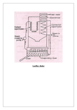
SlideShare a Scribd company logo
1 of 53
Download to read offline
Edited By
MOHAMMAD FAISAL KHAN
Integral University, Lucknow
2016
APPLIED THERMODYNAMICS LAB
INTEGRAL UNIVERSITY, LUCKNOW
APPLIED THERMODYNAMICS LAB
IME-352
List of Experiments
1. Study of La-Mont Boiler.
2. Study of Loffler Boiler.
3. Study the working of Domestic Refrigerator System.
4. Study and working of 2 stroke Petrol Engine.
5. Study and working of 4 stroke Petrol Engine.
6. Study and working of 4 stroke Diesel Engine.
7. Study and working of an Air Conditioner.
8. To determine the brake power of 4-stroke diesel Engine and making of heat
balance sheet.
9. To draw Heat balance Sheet for 2 Stroke Petrol Engine.
10. To Perform the Morse Test on 4 stroke 4 cylinder Petrol Engine
11. Study of Turbo-jet Engine Model
12. Study of Steam Power Plant
13. To draw the Valve Timing Diagram of a 4 stroke Diesel Engine and 4 stroke
Petrol Engine
EXPERIMENT NO. - 01
OBJECT - To study and sketch the model of La-Mont boiler
APPARATUS USED - Model of La-Mont boiler (steam pressures -12.8 MP, temperature-
5200
C, capacity - 45000)
WORKING PRINCIPAL OF LA-MONT BOILER
This is a modern high pressure water tube steam boiler working on a forced circulation. The
circulation is maintained by a centrifugal pump, driven by steam turbine, using steam for the
boiler. The forced circulation causes the feed water to circulate to the water walls and drums
equal to ten times of steam evaporated. The water from hot well is supplied to a storage and
separating drum and (boiler) through the economizer. The most of the sensible heat is
supplied to the feed water passing through the economizer. A centrifugal pump circulates the
water equal to 8 to 10 times the weight of steam evaporated. This water is circulated through
the evaporator tube and the part of the water evaporated, is separated in the separation drum.
The centrifugal pump delivers the feed water to headers at a pressure of 12.5 bars. Above the
drum pressure. The distribution headers distribute the water through the nozzle into an
evaporator. The steam separated in the boiler is further pass through the super heater and
finally supplied to the prime movers (turbine)
BOILER MOUNTINGS
These are the fitting, which are mounted on boiler for its proper and safe functioning. There
are many types of boiler mountings, which are as follows -
1. WATER LEVELINDICATOR
It is an important fitting, which indicates the water level inside the boiler to an observer. It is
a safety device, upon which correct working of the boiler depends.
2. PRESSURE GAUGE
A pressure gauge is used to measure the pressure of steam inside the steam boiler .It is fixed
in front of the steam boiler.
3. SAFETY VALVES
The function of safety valves is to blow off the steam when the pressure of steam inside the
boiler exceeds the working pressure.
4. STEAM STOPVALVE
It is the largest valve on the steam boiler. It is usually fitted to the highest part of the shell by
means of a flange. The main functions of stop valve are (1) To control the flow of steam from
boiler to main steam pipe. (2) To shut off the steam completely when required.
5. BLOW OFF COCK
The principle functions of blow-off cock are (1) To empty the boiler whenever required (2)
To discharge the mud, scale which are accumulated at the bottom of the boiler.
6. FEED CHECK VALVE
It is non-return valve, fitted to a screw spindle to regulate the lift. Its function is to regulator
the supply of water which is pumped into a boiler by a feed pump. This valve must have its
spindle lifted before the pump is started. It is fitted to the shell slightly below the normal
level of the boiler.
7. FUSIBLE PLUG
It is fitted to the crown plate of the furnace or the fire. Its object is to put off the fire in the
furnace of the boiler when the level of water in the boiler falls to an unsafe limit, and thus
avoids the explosion which may take place due to overheating of the furnace plate.
BOILER ACCESSORIES
These are devices which are used as integral part of a boiler, and help in running efficiency.
Through there are many types of boiler accessories, which are following.
1. FEED PUMP
The main function of the feed pump is to deliver the water to the boiler. The pressure of
steam inside the boiler is so high that the pressure of feed water has to be increased
proportionally before it is made to enter the boiler. Generally, the pressure of feed water is
20% more than that in the boiler in this boiler.
2. SUPERHEATER
A super heater is an important device of a steam generating unit. Its purpose is to increase the
temperature of saturated steam without rising its temperature.
3. ECONOMISER
An economizer is a device used to heat feed water by utilizing the heat of the exhaust flue
gas, before leaving through chimney. As the name indicates, the economizer improves the
economy of the steam boiler. The advantages of an economizer are as follows -
1.It reduces the losses of heat of the flue gasses.
2. It reduces the consumption of fuel
3. It improves the efficiency of boiler installation. (Material- iron steel)
4. AIR PREHEATER
An air pre-heater is used to recover heat from the exhaust flue gasses. It is installed between
the economizer and the chimney. The following advantages are obtained by using an air pre-
heater.
(1) The preheated air gives higher furnace temperature which result in more heat transfer to
water and thus increases the evaporative capacity per kg of fuel
(2) There is an increase of about 2% in the boiler efficiency for each 35-400
C rise in
temperature of air.
(3) It results in better combustion with less soot, smoke and ash.
(4) It enables a low grade fuel to be burnt with less excess air.
DISCUSSION:
1. What is boiler?
2. What do you understand by the drought?
3. What is the function of economizer?
4 What is the difference between fire tube and water tube boiler?
La-Mont Boiler
EXPERIMENT No. - 02
OBJECT - To study and sketch a high pressure boiler (Loeffler boiler).
APPARATUS - The model of Loeffler boiler
THEORY
A boiler is called a high pressure boiler when it operates with a steam pressure above 80 bar.
The high pressure boilers are widely used for power generation in thermal power plants .In
high-pressure boiler, if the feed water pressure increases, the saturation temperature of water
rises and the latent heat of vaporization decreases. The feed water can be heated to saturation
temperature in economizer with help of waste heat recovery from exhaust gases escaping to
chimney. Thus a boiler operation at high pressure will require less heat addition for steam
generator.
UNIQUE FEATURES OF HIGH PRESSURE BOILERS
1. Method of water circulation
2. Types of tubing
3. Improved method of heating
4. Pressurized combustion
5. Compactness
The novel feature of the Loeffler boiler is to evaporate water solely by means of superheated
steam. The heat is supplied only to economizer and super-heater. In other words, steam is
used as a heat absorbing medium. The major difficulty experienced in La-Mont boiler is, the
deposition of salt and sediment on the inner surfaces of water tubes. The deposition reduces
the heat transfer, ultimately, the generating capacity. This difficulty was solved in Loeffler
boiler by preventing the flow of water into the boiler tubes. Feed water is evaporated in the
drum using part of the superheated steam coming out from the water-heater. Thus only the
dry saturated steam passes through the tubes. Poor feed water can, therefore, be used without
any difficulty in the boiler, which is great advantage of this boiler.
A large no of steam generating plants are designed between working range 125 atm. and 510
o
C to 300 atm. and 660 o
C , these are the basically characterized as subcritical and super
critical . Usually a sub critical boiler consist of following components
PREHEATER (ECONOMIZER)
EVAPORATOR
SUPER HEATER
ASUPER CRITICALBOILER REQUIRES ONLY:
PREHEATER
SUPERHEATER
The constructional layout of both above types of boiler is however practically identical.
These days it has becomes a rule to use supercritical boiler above 300 MW capacity units.
The fuel cost with its poor quality, leads to search for more economical power generation
method which is possible by super critical steams cycle, where to generate steam on super
critical condition, the feed water is pressurized and supplied to heater unit.
In conventional boiler the water pressure is below the critical range. When water is heated
from room temperature onwards, it expands until it reaches to saturation temperature at given
pressure. If more heat is added to this saturated water, boiling begins and bubbles of steam
begins to form in water and rise above water level and the drum. During boiling, the
temperature remains constant, since only enthalpy of vaporization is added to water. This is
the saturated steam. Further heating of the saturated steam increases both its volume and
temperature and this is called superheated steam. Now, it is clear from p - h diagram, as the
pressure of water or steam rises, the enthalpy of vaporization decreases. When the critical
point is reached, the enthalpy of vaporization becomes zero and there is no constant
temperature boiling process.
Critical point is the point of intersection on 225 kg/cm2
pressure curve at 374 o
C. It means, if
the water is pressurized with the help of the feed pump up to critical pressure and then heat
added to it, the water will be directly converted to steam at temperature of 374 o
C and there
will be no boiling of water. Below critical pressure, water boils and is evaporated to steam.
But at or above critical pressure, there is no boiling and water changes to steam direct as, at
critical point density of water and steam is same. When this high pressure mixture is heated
above its saturation temperature 374 o
C, dry superheated steam is produced.
DESCRIPTION
Loeffler boiler is a water tube boiler using a forced circulation. Its novel principle is the
evaporation of the feed water by means of superheated steam from the super heater. The hot
gases from the furnace are primarily used for superheating purpose.
It has been experienced in La-Mount boiler, that deposition of salt and sedimentation of the
inner surface of water tube is unavoidable which reduces the heat transfer and intimately the
generating capacity. It also increases the danger of overheated the tubes due to salt
deposition, as it has high thermal resistance. These difficulty are solved in loeffler boiler by
preventing the blow of water into the boiler water tube. The high pressure feed pump draws
water through the economizer and delivers it into the evaporating drums. The steam
circulating pump draws saturated steam from evaporating drum and passes it through
radiative and convective super heater, where steam is heated to the required temperature.
From super heater about 1/3 of steam passes to prime mover and the remaining passes
through the water in evaporating drum in order to evaporate feed water. The nozzle which
distributes the superheated steam through the water pipe, are of special design to avoid
priming and noise. This boiler can carry higher salt concentration in water than any other
type and is more compact then indirectly heated boiler having natural circulation. Loeffler
boiler with generating capacity of 100 tonnes /hour and operating at 140 bar are already
commissioned.
RESULT
The steady and sketch of high pressure boiler like loeffler boiler is done.
QUESTIONS
1. Explain the Unique Features of High Pressure “boiler”.
2. What do you mean by supercritical and sub critical boiler? Explain ?
3. Draw an explanatory diagram of any H.P. boiler and label its components.
4. Explain the advantages of water tubing in high pressure boiler.
5. The combustion chamber H.P. boiler is construct in radiant form, explain its resonance.
6. Explain the concept of high pressure boiling in modern high pressure boiler.
7. What do you understand by critical point ? Explain it.
Loeffler Boiler
EXPERIMENT NO. - 03
OBJECT - To study the working of a Vapour Compression refrigeration system
APPARATUS - Model of refrigerator
INTRODUCTION
The terms refrigeration in a broad sense in used for the process of removing heat from a
substance. It also includes the process of reducing and maintain the temperature of body
below the temperature of surrounding. In other words, the refrigeration means a continued
extraction of heat from body, to maintain below the temperature of its surrounding. Thus in a
refrigerator, heat is virtually below the temperature of its surrounding i.e. heat is virtually
being pump from the lower temperature to a higher temperature. According to second law of
thermodynamics, this process can only be performed with the aid of some external work. It is
thus obvious, that supply of power is regularly required to drive a refrigerator. Theoretically,
the refrigerator is a reversed heat engine or a heat pump which pumps heat from colder body
and delivers it to a hotter body. The substance, which extract heat from a cold body and
deliver it to a hot body, is called refrigerant
A vapour compression refrigeration system is an improved type of air refrigeration system in
which, a suitable working substance, termed as refrigerant is used. The principle of vapour
compression refrigerator cycle involves the condensing and evaporating of the refrigerant
again and again. Freon-12 and Freon-22 are used as refrigerants which absorb a large amount
of heat from the system during evaporation and gives out latent heat to the atmosphere
during condensation.
WORKING PROCESS
The working process of Vapour Compression refrigerating system is followed in this
sequence
1- COMPRESSION PROCESS
The compression of vapour takes place from low pressure and low temperature to a high
pressure and high temperature in the compressor. The reciprocating compressors are
generally used in the refrigerators.
2- CONDENSATION PROCESS
Vapour under high pressure and high temperature is delivered to the condenser where its heat
is rejected to the atmosphere at constant pressure. This is carried out in two stages. The first
stage where the condensers absorb the heat from the high pressure vapour and the
temperature of the vapour falls to the saturation temperature. The second stage where the
vapour finally condensed to a liquid by rejection latent heat at constant pressure.
3- THROTTLING PROCESS
The high-pressure liquid refrigerant is expanded irreversibly through an expansion valve to a
lower pressure. During throttling enthalpy remains constant.
4- EVAPORATION PROCESS
Extremely wet vapour from the expansion valve passes through evaporator coil, where the
latent heat of system is absorbed by the wet vapour and consequently gets evaporated. The
final stage of refrigerant depend upon the quantity of heat absorb.
MAIN PARTS
A simple vapour compression system of refrigeration consist of four main parts
1- Compressor
2-Condenser
3-Expansion valve
4-Evaporator
QUESTION TO BE DUSCUSSED:
Q1- Draw P-H dig. For V.C. Refrigerator
Q 2-What is the function of expansion valve
Q3- Draw the fig. of V.C. refrigeration system cycle.
Q4- Explain the nomenclature of refrigerants?
Vapor Compression Refrigeration System
EXPERIMENT NO. - 04
OBJECT - To study the working of a 2 Stroke Petrol Engine.
APPRATUS USED - 2-Stroke petrol engine (cut model)
THEORY - 2-Stroke petrol engine have following main part.
CYLINDER
It is one of the most important parts of the engine, in which the piston moves to and fro in
order to develop power. It has to with stand very high pressure (about 70 bar) and
temperatures (about 2200° C) because there is direct combustion inside the cylinder.
Therefore, its material should be such that it can retain strength on high temperatures, should
be good conductor of heat and should resist to rapid wear and tear due to reciprocating parts.
Generally ordinary cast iron is used but in case of heavy duty engine. Alloy steels are used in
cast of multiple cylinder engines and the cylinders are cast in one block known as cylinder
block.
Sometimes, a liner or sleeve is inserted into the cylinder, which can be replaced when worm
out. As the material required for liner is comparatively small, it can be made of alloy cast
iron having long life and sufficient resistance to rapid wear and tear to the fast moving
reciprocating parts.
CYLINDER HEAD
It is fitted on one end of the cylinder, and acts as a cover to close the cylinder bore. The
cylinder head consists of a spark plug for igniting the fuel-air mixture, at the end of
compression stroke. The cylinder head is usually cast as one piece and bolted to one end to
the cylinder. Generally, the cylinder block and cylinder head are made up of the same
material. A copper or asbestos gasket is provided between the engine cylinder and cylinder
head air-tight air.
PISTON
It is considered as the heart of an I.C engine, whose main function is to transmit the force
exerted by the burning of charge to the connecting rod. The pistons are generally made of
aluminum alloys which are light in weight. They have good heat conducting property and
also greater strength at higher temperature.
PISTON RINGS
These are circular in shape and made of special grade cast iron. This material retains its
elastic property at very high temperature. The piston rings are housed in the circumferential
grooves provided on the outer surface of the piston. The function of the upper rings is to
provide air tight seal to prevent leakage of burnt gases into the lower position. Similarly, the
function of the lower rings is to provide effective seal to prevent leakage of the oil into the
engine cylinder.
CONNECTING ROD
It is usually a steel forging of circular, rectangular, I, T or H section and is highly polished
for increased endurance strength. Its small end forms a pin joint with the piston and its big
end is connected to the crank pin. It has a passage for the transfer lubricating oil from the big
end bearing to small end bearing (gudgeon pin). The special steel alloys of aluminum alloys
are used to manufacture the connecting rod. A special care is required for designing and
manufacturing of connecting rod, as it is subjected to alternatively compressive and tensile
stresses as well as bending stresses.
CRANK SHAFT
It is considered as the back bone of an I.C engine, whose function is to convert the
reciprocating motion of the piston into the rotary motion with the help of connecting rod.
This shaft contains one or more eccentric portions called cranks. Special steel alloys are used
to manufacture the crank shaft.
CRANK CASE
It is a cast iron case, which holds the cylinder and crank shaft of an engine. It also serves as a
sump for lubricating oil. The lower portion of the crank case is known as bed plate.
FLYWHEEL
It is mounted on crankshaft, whose function is to maintain its speed constant. It is done by
storing excess energy during the power stroke, which is returned during other strokes.
GOVERNOR
It is run by a drive from the crank shaft. The function of the governor is to regulate the
charge of engine and to maintain speed of the engine constant, when the load requirement
varies.
Note: Type of Governor:-
1. Centrifugal governors(Watt governor, Porter governor, Proell governor, Hartnell
governor, Hartung governor, Wilson-Hartnell governors)
2. Inertia governor.
PORTS
Ports are cut in the cylinder body to allow the flow of charge. There are three ports-
(1) Inlet Port (2) Transfer port and (3) Exhaust port
CRANK WEB
Crank web is provided in the crankshaft to counteract the tendency of bending of crank shaft
due to centrifugal action during engine operation.
CARBURETTOR
The function of the carburetor is to supply the uniform air-fuel to the cylinder of a petrol
engine through the intake manifold. The mass of the mixture entering the cylinder is
controlled by a throttle valve.
Note: Type of carburetors-zenith carburetor, solex carburetor, carter carburetor, S.U
carburetor.
SPARK PLUG
The function of spark plug is to initiate the mixture after completing the end of compression
in engine (petrol). It is generally mounted in the cylinder head. This is only used in petrol
engine.
The materials used for different parts of the engine are listed in the following table.
S.N. Engine Part Material Used Method of Manufacturing
1. Cylinder Cast iron, alloy steel Casting
2. Cylinder Head Cast iron, aluminum alloy Casting, forging
3. Piston Cast iron, Al-alloy Casting, forging
4. Piston ring Silicon cast iron Casting
5. Gudgeon pin Steel Forging
6. Connecting rod Steel Forging
7. Crank shaft Alloy steel Forging
8. Cylinder liner Cast iron, Nickel alloy steel Casting
9. Bearing White metal, lead bronze Casting
10. Crank case Cast iron, steel Casting
WORKING PRINCIPLE:
In a 2 – Stroke engine, one working cycle is completed in two strokes of piston and one
revolution of crank shaft. A two stroke petrol engine works on Otto cycle (constant volume
cycle). In this cycle, suction, compression, expansion and exhaust take place during two
strokes the piston. It means that there is one working stroke after every revolution of crank
shaft. A two stroke engine has ports instead of valves. All the four stages of a two stroke
petrol engine are described below.
1. SUCTION STROKE
In this stage, the piston, while going down toward BDC, uncovers both the transfer port and
the exhaust port. The fresh fuel-air mixture flows into the engine cylinder from the crank
case.
2. COMPRESSION STROKE
In this stroke, while moving up, first covers the transfer port and then exhaust port. After that
the fuel is compressed as the piston moves upward in this stroke, the inlet port opens and
fresh fuel-air mixture enters into the crank case.
3. EXPANSION STROKE
Shortly before this piston reaches the TDC (during compression strokes), the charge is
ignited with the help of a spark plug. It suddenly increases the pressure and temperature of
the products of combustion. But the volume, practically remains constant. Due to rise in the
pressure, the piston is pushed downwards with great force. The hot burnt gases expand due to
high speed of the piston.
4. EXHAUST STROKE
In this stage, the exhaust port is opened as the piston moves downwards. The products of
combustion, from the engine cylinder are exhausted through the exhaust port into the
atmosphere, the complete cycle and the engine cylinder is ready to suck the charge again.
IMPORTANT FEATURES
1. A petrol engine draws a mixture of petrol and air during suction stroke.
2. A petrol engine has compression ratio approximately from 6 to 10.
3. The charge is ignited with the help of spark plug.
4. Pressure at the end of compression is about 10 bars.
5. In two stroke petrol engine the lubricant is not filled directly into the crank case, as
the fresh charge comes into the crank case through inlet port, so the lubricant is
mixed with the fuel (petrol) to- provide lubrication.
6. In this engine suction and compression takes place at the same time.
7. In two stroke petrol engine, first suction takes place in crank case.
8. The process of removing burnt gases, from the combustion chamber of the engine
cylinder, is known as scavenging.
9. In two stroke engine, the scavenging is less effective.
10. In comparison to 4-stroke petrol engine, a 2-stroke petrol engine has double speed as
the one power cycle is completed in only one revolution of crank shaft for the same
power output.
11. The combustion of fuel takes place approximately at constant volume. In other words,
it works on Otto cycle.
12. The thermal efficiency of 2-stroke petrol engine is 26%
13. The two stroke petrol engines are generally employed in very light vehicles such as
scooters, mopeds, motor cycles and three wheelers.
Working Strokes of 2 Stroke Petrol Engine
EXPERIMENT NO. - 05
OBJECT - To study 4-Stroke petrol engine and its working.
EQUIPMENTS - Model of 4-stroke petrol engine. (Cut section)
CONSTRUCTION DETAILS OF 4-STROKE PETROL ENGINE
CYLINDER
It is the main part of the engine and made up of C.I, in which piston reciprocates to develop
power.
PISTON
Piston is of flat crown type and not of deflector type which is made up of C.I. The function
of piston is to compress the charge during compression stroke.
PISTON RINGS
Piston rings are slipped over piston and remain in contact with cylinder sleeve. They are of
two kinds viz. compression rings and oil control rings. Compression rings are generally made
of cast iron. An end gap is cut in piston rings for easy slipping over piston by expanding. The
oil control rings have oil vent all around its circumference.
FLYWHEEL
A flywheel is mounted on the crankshaft to take care of fluctuation in its speed during each
cycle of operation.
CAM SHAFT
Cam shaft is driven by the crankshaft through valve timing gears, several cam are mounted
on the cam shaft. The opening and closing of valves is governed by rotation of the cam.
INLET VALVE
Inlet valve allows the fresh charge to enter in to the cylinder.
EXHAUST VALVE
Exhaust valve allows removal of the products of combustion to go to the atmosphere via
silencer.
CRANKCASE
Crankcase is an enclosure for the crankshaft and consist of many others working parts of the
engine. It is located in lower region of engine.
VALVE OPERATING MECHANISM
Valve operating mechanism consists of following main components.
1- Tappet 2- Push rod 3- Rocker 4- Valve spring
The cams on the camshaft lifts the tappet during its rotation. The tappet actuates the push
rod, which in turn, operates the rocker arm about its fulcrum. The rocker arm exerts pressure
on the valves stem against the spring, to move the valve stem in the guide.
WORKING
The working cycle of the engine is completed in four strokes of piston and two revolutions of
crankshaft. Petrol is used as fuel.
SUCTION STROKE
During this stroke the piston moves from TDC to BDC, the inlet valve opens and
proportionate fuel air mixture is sucked in the cylinder. This operation is represented by the
line, 2-1. The exhaust valve remains closed throughout the strokes.
COMPRESSION STROKE
In this stroke the piston moves (2-3) towards T.D.C. and compresses the enclosed fuel air
mixture drawn in the engine cylinder during suction. The pressure of the mixtures rises in the
cylinder to a valve of about 8 bars. Just before the end of stroke the operating plug initiates a
spark which ignites the mixture and combustion take place at constant volume (3=4). Both
the inlet and exhaust valve remain closed during the stroke.
EXPANSION OR WORKING STROKE
When the mixture is ignited by the spark plug the hot gases are produced which drive the
piston from TDC to BDC and the engine shaft stores energy during this stroke. Both the
valve remains closed during the start of this stroke but when the piston just reaches the BDC.
EXHAUST STROKE
This is last stroke of the cycle. The removal of the gasses is comprised during this stroke.
The piston moves from BDC to TDC and the exhaust gasses are driven out of the cylinder;
this is also called scavenging (5-1).
DISCUSSION:
1. What is scavenging?
2. Why is the piston of a 2-stroke engine made defector type ?
3. What is stroke?
4. How an IC engine is starts?
5. What is a function of cam?
6. What is working of valve timing gears?
7. Why does used balancing weight?
8. What is difference between S.I. and C.I. engine?
9. What is the difference between 2-stroke and 4-stroke engine?
Working Strokes of 4 Stroke Petrol Engine
EXPERIMENT NO. - 06
OBJECT - To study 4-stroke diesel engine and its working.
APPARATUS USED - Model of 4-stroke diesel engine (vertical axis and sections model).
CONSTRUCTIONAL DETAILS
Four Stroke diesel engine consists of the following main parts.
1. Cylinder
2. Cylinder Head
3. Piston
4. Connecting Rod
5. Crank Shaft
6. Crank
7. Flywheel
8. Bearing (Main)
9. Big and small end bearing
10. Crank case
11. Bed plate
12. Piston plate
13. Intake valve
14. Exhaust valve
15. Cam shaft
16. Valve spring
17. Governor
18. Fuel Injection Pump
19. Atomizer
WORKING PRINCIPLE
The diesel engine is also known as compression ignition engine, (C.I.) or constant pressure
engine. A four stroke diesel engine has suction, compression, expansion and exhaust strokes
for each operating cycle. One working cycle is completed in 4-strokes of piston and two
revolutions of crankshaft (720o
crank angle).
1. SUCTION OR CHARGING STROKE
Suction stroke just begins before the piston reaches the top dead centre during its upward
movement in cylinder. The suction stroke begins at about 100
to 200
before top dead center
(TDC). During this stroke, inlet valve opens, piston from TDC begins to move down in
cylinder and low pressure is created inside the cylinder. At this moment, air enters in the
cylinder. The suction operation ends shortly after the piston reaches the bottom of its travel
(BDC). In terms of crankshaft rotation, the intake process ends at about 250
to 400
after
(BDC).
2. COMPRESSION STROKE
Compression stroke begins once the intake valve closes and thus seals off the cylinder space.
In this stroke, both the valves are closed and air is compressed as the piston moves upwards
from BDC to TDC. As a result of compression, pressure and temperature of the air increases
considerably.
3. POWER STROKE
Fuel is injected through the injector nozzle at the end of compression stroke. Power stroke
begins after all of the fuel is burnt. Piston is pushed down in cylinder by the expanding gases
produce by combustion. Nearly constant pressure is created on the piston about 600
to 700 C
after TDC. This is the point at which the orientation of piston, connecting rod and crankshaft
gives the greatest mechanical advantage and hence the gases exert the maximum force on the
crankshaft. During power stroke, work is done by the hot products of combustion on the
piston.
4. EXHAUST STROKE
Exhaust stroke occurs as the piston moves from BDC to TDC. The exhaust valve begins to
open before the end of power stroke i.e. before BDC. During exhaust stroke, work is done by
the piston on the products of combustion in expelling the same from the cylinder. This
completes the cycle and the engine cylinder is ready to suck the fresh air again.
APPLICATION
4-stroke diesel engines are widely used in transportation as bus, trucks, railway engines etc.
They are also used in construction machinery, earth moving equipments, off highway
vehicles and military vehicles.
IMPORTANT FEATURES
1. A diesel engine has compression ratio near about from 15 to 25
2. Pressure at the end of combustion is approximately 35 bars.
3. CI engines have of the mart efficiencies.
4. Diesel engines are being widely used because of the following advantages they possess
over other power plants.
a. Better fuel economy
b. Lower emissions
c. Reduced maintenance
d. Greater reliability
e. Good torque characteristics
f. Easy to supercharge
g. Longer service life
h. Highest power per unit wt. Of the engine
i. Lower fire hazard
j. High sustained torque
1. A diesel engine draws only air during suction stroke.
DISCUSSION
1. Define compression ratio, clearance volume and swept volume;
2. Define cut off ratio and expression ratio.
3. What is the difference between petrol and diesel engine?
4. What is working cycle?
5. What is bore and stroke of engine?
6. What is cubic capacity of an engine?
7. How does it affect the compression ratio of the horse power of an engine and
give formula?
8. Give the classification of internal combustion engines.
Working Strokes of 4 Stroke Diesel Engine
EXPERIMENT NO - 07
OBJECT - To study the working of an Air conditioner.
APPARATUS AND EQUIPMENTS - Model of an Air conditioner.
THEORY -
The air conditioning is that branch of engineering science which deals with the study of
conditioning of air for human comfort. It also studies with the conditioning of air for
industrial purposes, food processing, storage of food and other materials. The four important
factors for comfort of air conditioning are listed below.
1. Temperature of air (220
to 260
C)
2. Humidity of air (40% to 60%)
3. Purity of air
4. Motion of air(5m/min-8m/min)
COMPONENTS
It consists of the following components:-
1. Compressor
2. Condenser
3. Expansion Devices (capillary tube, solenoid, valve and thermostatic valve)
4. Evaporator
5. Filter dryer
6. Accumulator
7. Rotometer
8. Boiler
9. Heater coil
10. Wet bulb and Dry bulb temperature thermometer
11. Refrigerant
1. COMPRESSOR
The low pressure and temperature vapour refrigerant is drawn into the compressor through
the inlet or suction valve, where it is compressed to high pressure and temperature. This high
pressure and temperature vapour refrigerant is discharge into the condenser through the
delivery or discharge valve.
2. CONDENSER
The condenser or cooler consist of coil of pipe in which the high pressure and temperature
vapour refrigerant is cooled and condensed. The vapour gets converted into liquid
refrigerant. The refrigerant while passing through the condenser gives up its latent heat to the
surrounding condensing medium, which is normally air or water.
2. EXPANSION DEVICE
High-pressure and temperature liquid refrigerant expends in this devices and pressure and
temperature drop takes place.
(A) CAPILLARY TUBE
The copper capillary tube is 40 cm long and has an inside diameter of 0.75 mm. The
dimensions are based upon desired pressure difference between evaporator and condenser.
(B) SOLENOID VALVE
In many refrigeration systems the system is kept off when the temperature in the evaporator
increases or decreases below a particular temperature and restored again when the required
temperature is attained in the evaporator. This is accomplished using the solenoid valve.
(C) THERMOSTATIC VALVE
This valve controls the flow of refrigerant through the evaporator in such a way that the
quantity of vapour leaving the evaporator will be used for maintaining a constant degree of
superheat at the evaporator outlet.
(D) AUTOMATIC EXPANSION VALVE
It is also known as automatic expansion valve. It maintains the desired pressure difference
between evaporator and condenser through opening and closing of the needle valve
according to the requirement.
4. EVAPORATOR -
It consists of coils of pipe in which the liquid refrigerant at low pressure and temperature is
evaporated and changes into vapour refrigerant at low pressure and temperature. In
evaporating, the liquid refrigerant absorbs its latent heat of vaporization from the medium
(air, water or brine) which is to be cooled.
5. FILTER/DRIER -
It is usual practice to provide a filter or drier before the expansion device in order to prevent
troubles that may arise as a result of flow of suspended impurities and moisture.
6. ACCUMULATOR
It is a device which prevents the moisture contents present in the vapour refrigerant before
entering into the compressor, which can choke the valve of the compressor.
7. ROTOMETER
It is that device which measures the flow of fluid (liquid refrigerant) in litre/hour or Kg/s.
8. BOILER
During the winter season (cold climate conditions) hot water is generated in the boiler which
flows inside the coils of the air conditioning units through hot water pipes. Cold air, when
flows across these coils are maintained at required temperature to produce comfort
conditions during cold climate conditions.
9. HEATER COIL
During the dehumidification process the moisture content present in the air, is removed in the
heating coil.
10. DRY BULB AND WET BULB TEMPERATURE
The temperature of air recorded by thermometer, when it is not affected by the moisture
present in the air is called dry bulb temperature. The temperature of air when a wet cloth
surrounds the thermometer bulb, is called wet bulb temperature.
11. REFRIGERANT
A substance which absorbs heat through expansion or vaporization is termed as a refrigerant.
An ideal refrigerant should process chemical, physical and thermodynamic properties, which
permits its efficient applications in the refrigeration system. NH3, SO2, R-22,R-134a etc are
used as refrigerant.
QUESTIONS TO BE DISCUSSED
1. Define comfort. What are the factors which affect comfort air conditioning?
2. Define dry bulb and wet bulb temperature and humidity.
3. How will you define relative humidity?
4. What is psychometry? In what way is it related to an air conditioner?
EXPERIMENT NO. - 08
OBJECT - To determine the brake power of 4-stroke diesel engine and making of
heat Balance sheet.
APPARATUS
Single cylinder, 4-stroke diesel engine test ring with rope brake dynamometer and
hand tachometer.
MACHINE SPECIFICATION
A small capacity single cylinder, four strokes, vertical, water cooled, diesel engine,
test ring, rope brake dynamometer.
BHP: 5HP@1500RPM
Bore: 80mm
Stroke: 110mm
1. PANEL BOARD ARRANGEMENT
The units fitted on the dash board are:
1. An ignition and starting switch to switch on the ignition and to start the engine.
2. A Pilot lamp indicator for ignition.
3. Throttle valve control mechanism with an indicator to control the position of the throttle in
relation to the speed and load on the Engine.
2. FUEL INPUT MEASURINGARRANGEMENT
It consists of self-mounting type fuel tank of about 10 litres capacity suitably mounted on a
stand in turn, fixed on the air tank. Fuel goes from the reservoir to fuel filter.
3. ARRANGEMENT FOR MEASURING THE HEAT CARRIED AWAY BY THE
EXHAUST GASSES
It consists of an air tank fitted on orifice plate with orifice dia 30 mm and a differential
manometer to measure the rate of flow of air sucked by the engine. The coefficient of
discharge of orifice is about 0.6. The dial type thermometer is fixed on the table stand.to
measure the room temperature (air inlet temp).
4. ARRANGEMENT FOR MEASURING THE HEAT CARRIED AWAY BY THE
COOLING WATER
Suitable piping system is fitted to the engine for circulating the cooling water for the engine.
Two bulb type mercury thermometer are provided to measure the inlet and outlet temperature
of cooling water.
GENERAL DESCRIPTION
LOADING DEVICE -
A rope brake dynamometer arrangement with a brake drum coupled to the engine shaft and
provided with a cooling water arrangement, spring balance, a set of dead weights, mounted
along the engine on a substantial base plate to load the engine.
ADDITIONAL FLYWHEELARRANGEMENT -
Additional flywheel arrangement with a heavy flywheel mounted on two pedestals with ball
bearings. All mounted on a study base plate and dog clutch arrangement for determining the
frictional horse power of the engine using moment of inertia method by retardation.
STARTING -
Before starting, make sure that the fuel tank and fuel is cleaned by fuel oil and are free from
foreign matter. Fill the fuel tank with fuel oil to the required quantity. Prime the tubes with
fuel oil. Start the engine with the help of the starting handle supplied. While starting, the
engine should be unloaded. As soon as the engine starts and picks up speed it comes under
the governor and will run on the rated speed.
STOPPING -
Remove all the dead weights on the weight hanger and run the engine at load for a few
minutes. Stop the cooling water supply to the brake drum. Push the fuel pump rack operating
lever towards the pump and hold it in that position by turning off the fuel supply.
THEORY -
The brake power (briefly written as BP) is the power available at the crank shaft. The brake
power of an I.C. engine is usually measured by means of brake mechanism (rope brake or
prony brake.)
FORMULA USED -
1. BP = 2πNT/60
Where T = (W-S) D/2
= πN (W-S) D/60
2. Fuel consumption : mf = kg/hr
3. Total heat generated = mf . c
Where c = calorific volume of petrol/diesel = 44,000KJ/Kg
4. Mass of air ma = 140 . cd . A .√ρh kg/ hr
Where Cd = 0.8
A = 2.8 x
5. Heat carried away by exhaust gasses = (ma+mf) . cp . ∆T
6. Heat carried away by cooling water = mc . ρ . ∆T
7. Air fuel ratio = mf / ma
8. Heat unaccounted.
Heat lost by radiation by difference (A-B) kJ
PROCEDURE -
Start the engine and run it for few minutes. After the engine gets heated up i.e. the running
conditions are stabilized start taking readings. The power developed by engine is measured
with the help of rope brake arrangement. The brake drum is of 300 mm. dia and rope 15 mm
dia. The speed can be noted by using a hand tachometer. From the speed and the load on the
brake drum, the power can be calculated.
TO DRAW A HEAT BALANCE SHEET FOR 4 STROKE DIESEL
ENGINE
PROCUDURE:
1. The fuel is first filled in the fuel tank.
2. Then the cooling arrangements are made.
3. Before starting the engine the brake drum circumference is noted.
4. Before starting check and assure that there is no load on the weight
hanger.
5. Now the engine is started and for 1 minute fuel consumption is
noted with the help of a stop watch.
6. Now place weight in the weight hanger and take the above
mentioned readings. The spring balance reading is also noted down.
8. The calculations are done.
9. Note the following readings for particular condition,
a. Engine Speed
b. In 1 minute____ml of diesel consumption
c. Tachometer reading.
d. Manometer readings, in mm of water
e. Temperatures at different locations.
f. Consumption of water in 1 minute.
10. After the completion release the load and then switch of the
engine.
11. Allow the water to flow for few minutes and then turn it off.
RESULT -
The brake power of 4-stroke diesel engine is ____
EXPERIMENT NO. - 09
OBJECT - To draw Heat balance Sheet for 2 Stroke Petrol Engine.
DESCRIPTION -
Single cylinder Two Stroke Petrol Engine air cooled 3000 r.p.m Bajaj make. The engine,
coupled with electrical Dynamometer. The rig completes with the following.
1. A panel Board with Volt meter, Amps meter and elec.bulbs.
2. A fuel input measuring arrangement.
3. Arrangement for measuring heat carried away by exhaust gas.
FUEL INTAKE MEASURINGARRANGEMENT -
A fuel tank about 5 lit. capacity is mounted on a sturdy iron stand. Fuel goes from the
reservoir to engine through fuel measuring apparatus. Measuring of fuel consumption for a
partial time can be taken by a stop watch.
ARRANGEMENT FOR THE MEASUREMENT OF AIR AND HEAT CARRIED
AWAY BY THT EXHAUST GASES -
It consists of an air tank placed on the iron stand. An orifice of dia. 15 mm fitted on the tank
and a manometer to measure the rate of flow of air sucked by the engine. One distant reading
digital type thermometer is mounted on the panel board to read the temperature of the exhaust
gases.
STARTING -
Before starting make sure that the fuel tank and the fuel line is filled with fuel. Then start the
engine by kicking. While starting, the clutch may be disengaged to start the engine at no load.
After starting the engine, the clutch may be slowly engaged and at the same time, engine is
accelerated gradually. Run the engine at the rated speed. The speed may be measured by a
hand tachometer, to ensure that both engine and dynamometer are working smoothly. Now the
engine is ready for test.
STOPPING -
Reduce the load by switching off the bulbs and reduce the throttled gradually so that the
engine runs at low speed. Declutch the dynamometer from the engine and stop the engine.
TESTING -
The power developed by the engine, is measured with the help of an electrical dynamometer.
By glowing the bulbs on the electrical panel, power developed by the engine can be found
out. Special arrangements are also provided to measure the mechanical load. A spring balance
is used to measure the load in kg. The speed is found out by using a hand tachometer. From
the speed and load in spring balance, power can be calculated.
FUEL MEASURING ARRANGEMENT -
Arrangement for measuring fuel consumed by the engine, consists of a fuel tank mounted on a
stand with burette three way cock and connecting tubes.
AIR INTAKE MEASURING -
M.S. air reservoir of suitable size an orifice of 0.6 cm. with manometer of 0.5 m long tube.
Strong iron stands to hold the tank, a dia type thermometer fitted in the engine exhaust line to
measure the exhaust gas temperature.
TEST READING:-
• Duration of run....................................
• Fuel consumption....................................
• Speed in r.p.m......................................
• Manometer reading in C.M...................................
• Load in mechanical.......................................
• Load in Electrical. .......................................
• Exhaust gas temp. ..................................
RESULT:-
1. B.H.P.=2πNT/4500
Where N= Speed in r.p.m.
T= Torque (radius of dynamometer * spring balance reading).
2. In the case of Electrical Load = 2*Volt *Amp. Watt
The clutch gear ratio is 2:1
3. Air fuel ratio = Mass of the air drawn/min/ Consumption of fuel/min.
EXPERIMENT NO. - 10
OBJECT - To perform Morse test on 4-stroke engine test rig.
COMPONENT OF TESTING - Multi cylinder, 4-stroke petrol engine test rig with
hydraulic dynamometer. It mainly consists of:
1. Multi cylinder petrol engine.
2. A hydraulic dynamometer.
3. A panel board arrangement.
4. A fuel input measuring arrangement.
5. An arrangement for measuring heat carried away by exhaust gases
6. An arrangement for measuring heat carried away by the cooling water.
GENERAL DESCRIPTION -
MULTI-CYLINDER PETROL ENGINE - A medium capacity 4-stroke water cooled
petrol engine. The specification of the engine as follows:
Rated H.P. - 10 H.P. @ 1500 RPM
No. of cylinders - 4
Cylinder bore - 84mm.
Stroke - 95.04mm.
MORSE TEST –
The indicated horse power of the engine can be found out for set position of the throttle and
choke and for a selected engine speed by cutting of each cylinder in knife switches. These
switches are provided in the panel board for cutting of each of the cylinder of the engine.
With the help of the knife switches any one of the cylinders can be cut off and by breaking
the secondary voltage of the ignition coil and preventing the plug action. Run the engine with
all the cylinders and note the power developed. Then cut off the required cylinder by the
respective knife. Adjust the speed of the engine (cylinder) to its original value by reducing
the load form the dynamometer without changing the throttle position. Note down the power
developed in three working cylinders. Thus the power developed between 4th-cylinder and
3rd-cylinder is the (Indicated Horse Power ) of the cut off cylinder.
Repeat the same procedure for the rest of the three cylinders individually and find out their
respective IHP. By adding the IHP of the 4-cylinders the total IHP of the engine can be found
out. With the observed BHP and calculated IHP the mechanical efficiency of the engine can
be calculated. The Morse test is carried out by only after running conditions are stabilized at
the required BHP, then a cylinder is cut off. Speed is adjusted by unloading quickly,
sometime might result in the change in the working condition of the engine. Immediately
after the required observation are made, run the engine with all the four cylinders working.
Minimizing the running time of the engine with a shut off cylinder, two cylinders should not
be cut off simultaneously
Let I1, I2, I3 and I4 = indicated power of each individual cylinder.
F1, F2, F3 and F4 = frictional power of each individual cylinder.
Total brake power of engine when all the cylinders are working is given by,
B= (Total Indicated Power) - (Total Frictional Power)
B = (I1+I2+I3+I4) - (F1+F2+F3+F4)……………….. (1)
When the cylinder No. 1 is cut off, then I1 = 0, but the frictional losses of the cylinder remain
the same. Bake power of remaining three cylinders,
B1= (I2+I3+I4) - (F1+F2+F3+F4).................... (2)
Subtracting equation (2) from the equation (1)
I1 = B-B1
Similarly,
I2 = B-B2
I3 = B-B3
I4 = B-B4
And total indicated powe4r of engine
I = I1+I2+I3+I4
CALCULATION -
1. Fuel consumption: mf =----------kg/hr
2. BHP (B) = WN/2000 watt (for 4-cylinder)
B1= WN/2000 watt (when cylinder no. 1 is cutoff)
B2= WN/2000 watt (when cylinder no. 2 is cutoff)
B3= WN/2000 watt (when cylinder no. 3 is cutoff)
B4= WN/2000 watt (when cylinder no 4 is cutoff)
Where W = Load indicated by the weighing machine in kg.
N = Shaft speed (rpm)
EXPERIMENT NO. - 11
OBJECT - To study the model of Turbo-jet Engine (Gas Turbine).
APPARATUS USED - Model of Turbo-jet Engine (Gas Turbine)
WORKING PRINCIPLE -
The turbojet is a jet engine, usually used in aircraft. It consists of a gas turbine with a propelling
nozzle. The gas turbine has an air inlet, a compressor, a combustion chamber, and a turbine (that
drives the compressor). The compressed air from the compressor is heated by the fuel in the
combustion chamber and then allowed to expand through the turbine. The turbine exhaust is then
expanded in the propelling nozzle where it is accelerated to high speed to provide thrust. Turbojets
have been replaced in slower aircraft by turboprops which use less fuel. At higher speeds, where
the propeller is no longer efficient, they have been replaced by turbofans. The turbofan is quieter
and uses less fuel than the turbojet. Turbojets are still common in medium range cruise missiles,
due to their high exhaust speed, small frontal area, and relative simplicity.
The jet engine is only efficient at high vehicle speeds, which limits their usefulness apart
from aircraft. Turbojet engines have been used in isolated cases to power vehicles other than
aircraft, typically for attempts on land speed records. These are common in helicopters and
hovercraft. Turbojets have also been used experimentally to clear snow from switches in rail
yards.
DESCRIPTION OF DIFFERENT COMPONENTS
AIR INTAKE
An intake, or tube, is needed in front of the compressor to direct the incoming air smoothly
into the moving compressor blades. Older engines had stationary vanes in front of the
moving blades. These vanes also helped to direct the air onto the blades. The intake is also
shaped to minimize any flow losses when the compressor is accelerating the air through the
intake at zero and low aircraft speeds. These vanes also serve the purpose to slow the flow
down for the compressor, when the aircraft is operating above Mach 1. The air flowing into a
turbojet engine must always be subsonic, regardless of the speed of the aircraft itself.
COMPRESSOR
The compressor is driven by the turbine. It rotates at high speed, adding energy to the airflow
and at the same time squeezing (compressing) it into a smaller space. Compressing the air
increases its pressure and temperature. The smaller the compressor the faster it turns. At the
large end of the range the GE-90-115 fan rotates at about 2,500 RPM while a small
helicopter engine compressor rotates at about 50,000 RPM.
In most turbojet-powered aircraft, bleed air is extracted from the compressor section at
various stages to perform a variety of jobs including air conditioning/pressurization, engine
inlet anti-icing and turbine cooling. Bleeding air off decreases the overall efficiency of the
engine, but the usefulness of the compressed air outweighs the loss in efficiency. Early
turbojet compressors had overall pressure ratios as low as 5:1. Aerodynamic improvements
including splitting the compressor into two separately rotating parts, incorporating variable
blade angles for entry guide vanes and stators, enabled later turbojets to have overall pressure
ratios of 15:1 or more. For comparison, modern civil turbofan engines have overall pressure
ratios of 44:1 or more.
After leaving the compressor, the air enters the combustion chamber.
COMBUSTION CHAMBER
The burning process in the combustor is significantly different from that in a piston engine.
In a piston engine the burning gases are confined to a small volume and, as the fuel burns,
the pressure increases. In a turbojet the air and fuel mixture burn in the combustor and pass
through to the turbine in a continuous flowing process with no pressure build-up. Instead
there is a small pressure loss in the combustor.
The fuel-air mixture can only burn in slow moving air so an area of reverse flow is
maintained by the fuel nozzles for the approximately stoichiometric burning in the primary
zone. Further compressor air is introduced which completes the combustion process and
reduces the temperature of the combustion products to a level which the turbine can accept.
Less than 25% of the air is typically used for combustion, as an overall lean mixture is
required to keep within the turbine temperature limits.
TURBINE
Hot gases leaving the combustor expand through the turbine. Typical material for turbines
include Inconel and Nimonic. The turbine vanes and blades have internal cooling passages.
Air from the compressor is passed through these to keep the metal temperature within limits.
In the first stage the turbine is largely an impulse turbine (similar to a pelton wheel) and
rotates because of the impact of the hot gas stream. Later stages are convergent ducts that
accelerate the gas. Energy is transferred into the shaft through momentum exchange in the
opposite way to energy transfer in the compressor. The power developed by the turbine
drives the compressor as well as accessories, like fuel, oil, and hydraulic pumps that are
driven by the accessory gearbox.
NOZZLE
After the turbine, the gases expand through the exhaust nozzle producing a high velocity jet.
In a convergent nozzle, the ducting narrows progressively to a throat. The nozzle pressure
ratio on a turbojet is high enough at higher thrust settings to cause the nozzle to choke.
If, however, a convergent-divergent (de Laval nozzle) is fitted, the divergent (increasing flow
area) section allows the gases to reach supersonic velocity within the divergent section.
Additional thrust is generated by the higher resulting exhaust velocity.
THRUST AUGMENTATION
Thrust was most commonly increased in turbojets with water/methanol injection or
afterburning. Some engines used both at the same time.
AFTERBURNER
An afterburner or "reheat jet pipe" is a combustion chamber added to reheat the turbine
exhaust gases. The fuel consumption is very high, typically four times that of the main
engine. Afterburners are used almost exclusively on supersonic aircraft, most being military
aircraft.
BASIC WORKING CYCLE -
The Brayton cycle represents the air-standard model of a gas turbine power cycle. A simple
gas turbine is comprised of three main components: a compressor, a combustor, and a
turbine. According to the principle of the Brayton cycle, air is compressed in the turbine
compressor, the air is then mixed with fuel, and burned under constant pressure conditions in
the combustor. The resulting hot gas is allowed to expand through a turbine to perform work.
Most of the work produced in the turbine is used to run the compressor and the rest is
available to run auxiliary equipment and produce power. The gas turbine is used in a wide
range of applications. Common uses include stationary power generation plants (electric
utilities) and mobile power generation engines (ships and aircraft).
A jet engine powered aircraft is propelled by the reaction thrust of the exiting gas stream.
The turbine provides just enough power to drive the compressor and produce the auxiliary
power. The gas stream acquires more energy in the cycle than is needed to drive the
compressor. The remaining available energy is used to propel the aircraft forward.
CYCLE ANALYSIS
Thermodynamics and the First Law of Thermodynamics determine the overall energy
transfer. To analyze the cycle, we need to evaluate all the states as completely as possible.
Air standard models are very useful for this purpose and provide acceptable quantitative
results for gas turbine cycles. In these models the following assumptions are made.
1. The working fluid is air and treated as an ideal gas throughout the cycle;
2. The combustion process is modeled as a constant-pressure heat addition;
3. The exhaust is modeled as a constant-pressure heat rejection process.
Working Cycle (Brayton cycle)
Thermal Efficiency
The thermal efficiency is defined differently for a Brayton jet engine cycle than for a Brayton
cycle for power production. For the jet engine case, the thermal efficiency is defined as the
ratio of the rate of addition of kinetic energy to the air to the rate of energy input to the
combustor. For the case when the engine is at static conditions, the efficiency becomes
Efficiency=Vexit
2
/Qcomb.
Questions to be discussed:
1. Explain the compounding of gas turbine.
2. What is the working of gas turbine?
3. Explain the working of nozzle in turbo jet Engine
EXPERIMENT NO. - 12
OBJECT - To study and sketch THERMAL POWER PLANT.
APPARATUS - The model of Thermal Power Plant available in Lab.
THEORY - A steam power plant, also known as thermal power plant, uses steam as working
fluid. Steam is produced in a boiler using coal as fuel and is used to drive the prime mover,
namely, the steam turbine. In the steam turbine, heat energy is converted into mechanical
energy, which is used for generating electric power. Generator is an electro-magnetic device
which makes the power available in the form of electrical energy.
It consists of four main circuits. These are -
 Coal and ash circuit.
 Air and flue gas circuit
 Water and steam circuit and
 Cooling water circuit
COALAND ASH CIRCUIT -
Coal from the storage yard is transferred to the boiler furnace by means of coal handling
equipment like belt conveyor, bucket elevator, etc. Ash, resulting from the combustion of coal in
the boiler furnace is collected at the back of the boiler and is removed to the ash storage yard
through the ash handling equipment.
AIR AND FLUE GAS CIRCUIT -
Air is taken from the atmosphere to the air preheater. Air is heated in the air preheater by the heat of
flue gas which is passing through the chimney. The hot air is supplied to the furnace. The flue gases
after combustion in the furnace pass around the boiler tubes. The flue gases then pass through a dust
collector, economizer and pre-heater before being exhausted to the atmosphere through the chimney.
By this method the heat of the flue gases, which would have been wasted otherwise, is used
effectively. Thus the overall efficiency of the plant is improved.
AIR POLLUTION –
The pollution of the surrounding atmosphere is caused by the emission of objectionable
gases and dust through the chimney. The air pollution and smoke cause nuisance to people
surrounding the planet.
FEED WATER AND STEAM CIRCUIT -
The steam generated in the boiler passes through super heater and is supplied to the steam
turbine. Work is done by the expansion of steam in the turbine and the pressure of steam is
reduced. The expanded steam then passes to the condenser, where it is condensed.
The condensate leaving the condenser is first heated in a low pressure (L.P.) water heater by
using the steam taken from the low pressure (H.P.) extraction point of the turbine. Again steam
taken from the high pressure extraction point of the turbine is used for heating the feed water in
the H.P water heater. The hot feed water is passes through the economizer, where it is further
heated by means of flue gases. The feed water which is sufficiently heated by the feed water
heaters and economizer is then fed into the boiler.
COOLING WATER CIRCUIT -
Abundant quantity of water is required for condensing the steam in the condenser. Water
circulating through the condenser may be taken from various sources such as river or lake,
provided that adequate water supply is available from the river or lake throughout the year.
If adequate quantity of water is not available at the plant site, the hot water from the condenser is
cooled in the cooling tower or cooling ponds and circulated again.
Advantages of thermal power plants
• Initial cost is low compared to hydro-plant.
• The power plant can be located near load center, so the transmission losses are
considerably reduced.
• The generation of power is not dependent on the nature’s mercy like hydro plant.
• The construction and commissioning of thermal plant requires less period of time
than a hydro plant.
A thermal power station using steam as working fluid, works basically on the Rankin cycle.
Steam is generated in the boiler, expanded in the prime remover and condensed in the
condenser and fed into the boiler again. However, in practice, there are numerous
modification and improvements in this cycle with the aim of affecting heat economy and to
increase the thermal efficiency of the plant. Beside above main units, a number of auxiliary
units are also needed.
A boiler uses coal or oil as the fuel stored in the plant. A coal or fuel handling plant is
mandatory to maintain the regular supply of fuel to the boiler. In case of coal fired, the
boilers 10% to 15% of the total rate of the coal fired is collected in the form of ash. A huge
quantity of coal is required for large thermal power stations. A thermal power plant of 500
MW capacity requires about 5000 to 6000 tonnes of the coal per day. Thus it will produce
500 to 600 tonnes of ash per day. To remove this ash, from furnace, ash handling system is
required, which will transfer ash from boiler furnace to ash storage.
DESCRIPTION:
Following are the main silent elements of a thermal power plant as given below:
1. Boiler (steam generator) 2.Steam Turbine
3. Generator 4.Condenser
5. Cooling Tower 6.Water treatment plant
7. Boiler Feed Pump 8.Iunduced Draft Fan & Forced Draft fan
9. Ash Precipitators 10.Chimney
11. Control Room
1. BOILER -
The water is converted into steam in the boiler with the help of heat produced by the burning
of coal. The boiler consists of a tall structure line with the tubes, which may be as tall as
10m. The boiler can be either fire-tube or water-tube boiler. The modern boilers are all water
tube boilers in which water flows through the tubes and combustion gases flow across the
tubes. A Modern boiler may be producing steam at the rate of 500 tonnes/hr at a pressure 300
kg/cm2
and temperature 5400
C and burning coal at the rate of 200 tonnes/hr. The
temperature inside the furnace where fuel is burnt is of the order 15000
C. The boiler also
contains separate set of tubes, which constitute heat exchangers in which heat in the flue
gases in exchanged with other mediums. These are:-
 Super Heater
 Economizer
 Reheater
 Air-Heater
SUPERHEATER -
The super heater is situated at the hottest part of the boiler. It is meant to raise the steam
temperature above the saturation temperature by absorbing heat from the flue gases. The
maximum temperature to which steam can be heated will depend upon the metallurgy and
economy in initial cost and maintenance cost of the super heater. The present trend is to keep
the steam temperature at 5400
C. The superheating of steam makes it possible to recover
more energy from steam which improves the cycle efficiency of the plant. It also eliminates
the formation of water vapour during conveying of steam in pipe lines and during its early
flow through the turbine blades. From the super heater, the steam is led to high-pressure
turbine.
REHEATER -
The function of the reheater, is to raise the temperature of steam after it has expanded in the
high-pressure turbine. After being reheated, it passes through the intermediate and low-
pressure turbines. In reheater also, the temperature of steam is limited to 5400
C.
ECONOMISER -
The function of an economizer in a boiler is to absorb heat from the outgoing flue gases, to
raise the temperature of the feed water coming from the condenser, before it enters the
evaporative section of the boiler. It is usually located ahead of air heaters and following the
super heater and reheater in the flue gas stream.
AIR HEATER -
The function of the air heater in a boiler is to raise the temperature of air with the help of
outgoing flue gasses, before the air is led to the furnace for the combustion of fuel. The
employment of economizer air-heater increases the efficiency of the boiler.
2. STEAM TURBINE -
The steam turbine is the main prime mover used for producing power. The function of steam
turbine is to convert the heat energy of the steam into rotational power of the shaft on which
turbine is supported. The turbine can also be tapped at several points to supply steam for
preheating the condensate of condenser. Each of these extractions opening is connected to a
feed water heater. The rotation of speed of the turbine shaft is set by the frequency of the
electricity supply and is 3000 rpm, corresponding to an alternating electric supply at 50 Hz.
The turbine is fitted with a precise oil operated speed governor.
3. GENERATOR -
The generator which is directly coupled to the turbine shaft converts mechanical energy of
the shaft into electrical energy. It consists of two electrical windings. One is mounted on the
turbine shaft, rotating with it, and is called the rotor. The other is arranged as a shroud around
the rotor, fixed to the floor, and is called the stator. The relative motion of rotor and stator
generates the electricity. The generator produces electricity at 11000 volts, or so.
4. CONDENSER -
The function of the condenser is to condense the steam which has been discharged from low-
pressure turbine. The condenser is a large vessel containing a large number of brass-tubes
through which the cold water is circulated continuously for condensing the steam flowing
outside the surface of the tubes. The hot condensate flows back to the boiler to be
reconverted into steam. The use of condenser increases the output of the plant by lowering
the exhaust pressure of steam on prime mover and also provides hot feed water for the boiler.
5. COOLING TOWERS -
The function of the cooling tower is to cool the hot cooling water coming out of the
condenser, in closed recirculation cooling water system. Here the hot water is cooled in
contact with the atmospheric air. The air is drawn through the bottom of the cooling tower by
induced draft fans are mounted at the top of the cooling tower. The flow of the air upward
through the cooling tower can also be produced either by forced draft fan or it may be natural
draught. Whereas, the hot cooling water falls vertically from the top of the cooling tower.
The cold cooling water gets collected in the cooling tower basin and is pumped back to the
condenser. The tower may be the made up of a metal or of Ferro-concrete and may be as tall
as a 40 storey building. A cooling tower may cool 18,000 tones of water per hour by 100
C.
6. WATER TREATMENT PLANT -
To avoid any formation in boiler tube and to prevent priming or foaming problems, the feed
water, used in the boilers has to be treated in water treatment plant. The daily make up water
supply which may run into hundreds of tonnes is also produced in water treatment plant.
7. BOILER FEED PUMPED -
A boiler feed pump is like a heart of power plant. Its aim is to supply feed water coming
from the condenser to the boiler at higher pressure. This is one of the most sophisticated
pumps and is the largest auxiliary of the power plant. Usually, for each unit, two feed water
pumps are provided.
8. ID FANS & FD FANS -
The function of the induced draught fan is to exhaust ash laden flue gasses through the
interior of the boiler and dust extracting equipment and to the chimney. The fans are axial
type and are driven by an electric motor. Usually, for each unit 2 to 10 fans are provided. The
aim of the forced draught fan is to draw air from the top of the boiler house and pass it
through the air preheaters, to the hot air duct. From the duct, some of the air passes directly
to the fuel burners and the remaining are taken through the primary air fan to the pulverizing
mill, where it is mixed with the powdered coal, blowing it along pipes to the burners of the
furnace.
9. ASH PRECIPITATORS -
To avoid air pollution, the outgoing fuel gases should be freed from dust particles before
these escaping into the atmosphere through the chimney. This is done with the help of two
precipitators: Mechanical and electrical. In mechanical precipitators, the coarser ash particles
are separated by centrifugal action. In electrostatic precipitator, which removes finer ash
particles, the flue gas is made to pass through high voltage electric field. The ash particles get
ionized and are attracted towards the collecting electrodes. The ash so separated out of the
gases is collected in the hoppers underneath and further disposed off in ash disposal area.
10. CHIMNEY -
The flue gases from the boiler, after removal of the fly ash in the precipitators, are let off to
atmosphere through boiler chimney. It is a tall Ferro-concrete structure linked with the fire
bricks for protection of Ferro- concrete against hot fuel gases. A protective coating of acid
resistance paint is applied outside on its top 10 meters.
10. CONTROL ROOM -
The control room is the operational nerve center of a thermal power station. The performance
of all plant equipment is constantly monitored here with the help of sophisticated
instrumentation and controllers. Any adverse deviation in the parameters of the various
systems is immediately indicated by visual audio warning and suitable corrective action is
taken, accordingly.
CHARACTERSTICS OF THERMAL POWER PLANT -
The desirable characteristics for a stem power plant are as follows:
* Higher efficiency
* Lower cost ability
* Ability to burn coal especially of higher ash content and inferior coals.
* Low – water requirement.
* Higher reliability.
RESULT -
The study and sketch of thermal power plant is done.
QUESTIONS -
1. What is Rankin cycle? Explain.
2. Explain cooling water circuit of thermal power plant.
3. Describe the need of ID fan and FD fan, in a TPP.
4. Sketch a general layout of a modern thermal power plant.
Layout of Thermal Power Plant
EXPERIMENT NO. - 13
OBJECT - To draw a valve timing diagram of a 4-stroke diesel engine on its cut section
model.
INTRODUCTION -
A valve timing diagram is a graphical representation of the exact moments, in sequence of
operations, at which two valves (i.e. inlet and exhaust valves) - open and close as well as
firing of fuel takes place. It is generally, expressed in terms of angular positions of the
crankshaft.
DISCRIPTION -
In the valve timing diagram, inlet valve opens before the piston reaches TDC, or in other
words while the piston is still moving up before the combustion starts. When the piston
moves from TDC to BDC suction stroke starts. The piston reaches the BDC and starts
moving up, the inlet valve closes, and the crank has moved a little up the BDC. This is done
because incoming air continues flow into the cylinder although the piston is moving upwards
from BDC. Now the air is compressed with both valves closed. Fuel valve opens just before
the piston reaches the TDC. Now the fuel is injected in the form of very fine spray, into the
engine cylinder, which gets ignited due to high temperature of the compressed air. The fuel
valve closes after the piston has come down a little from the TDC. This is done as the
required quantity of the fuel is injected into the engine cylinder. The burnt gases (under high
pressure and temperature) push the piston downwards, and the expansion or working stroke
takes place. Now the exhaust valve opens before the piston again reaches BDC and the burnt
gasses start, leaving the engine cylinder. The piston moves from BDC to TDC and thus
performing the exhaust stroke. The inlet valve opens before the piston reaches TDC to start
suction stroke. Thus the cycle is repeated.
TDC - Top dead center
BDC - Bottom dead center
IVO -Inlet valve opens (10°-20° before TDC)
IVC -Inlet valve closes (25°-40° after BDC)
FVO -Fuel valve opens (10°-15° before TDC)
FVC -Fuel valve closes (15°- 20° after TDC)
EVO -Exhaust valve opens (39°-50° before BDC)
EVC -Exhaust valve closes (10°-15° after TDC)
TO DRAW THE VALVE TIMING DIAGRAM FOR THE FOUR
STROKE DIESEL ENGINE
PROCEDURE:
1. First the TDC and BDC of the engine are found correctly by rotating the flywheel and the
positions are marked on the flywheel.
2. Now the circumference of the flywheel is found by using the measuring tape.
3. The flywheel is rotated and the point at which the inlet valve starts opening is found out
and its position is marked on the flywheel.
4. Similarly the position at which it closes is also found out.
5. The distances are measured by using thread with respect to their dead Centre and
converted into angles.
6. The same procedure is repeated for the exhaust valves also.
OBSERVATIONS -
TDC BDC
BEFORE AFTER BEFORE
IVO
IVC
FVO
EVO
EVC
RESULT - We study and draw the valve timing diagram of 4-stroke diesel engine.

More Related Content

Similar to mech 2nd yr lab report.pdf

MET 401 Chapter 4 boilers_and_steam_generators
MET 401 Chapter 4 boilers_and_steam_generatorsMET 401 Chapter 4 boilers_and_steam_generators
MET 401 Chapter 4 boilers_and_steam_generatorsIbrahim AboKhalil
 
mounting and accessories of boiler in eme
mounting and accessories  of boiler in eme mounting and accessories  of boiler in eme
mounting and accessories of boiler in eme Pratik Patel
 
Water and fire tube boilers
Water and fire tube boilersWater and fire tube boilers
Water and fire tube boilersTariq Jamshaid
 
High pressure boilers 050,18,48
High pressure boilers 050,18,48High pressure boilers 050,18,48
High pressure boilers 050,18,48Maharshi Soni
 
SUMMER INTERNSHIP(INDUSTRAIL REPORT) ON THERMAL POWER PLANT
SUMMER INTERNSHIP(INDUSTRAIL REPORT) ON THERMAL POWER PLANT SUMMER INTERNSHIP(INDUSTRAIL REPORT) ON THERMAL POWER PLANT
SUMMER INTERNSHIP(INDUSTRAIL REPORT) ON THERMAL POWER PLANT Amit Gupta
 
How to improve the efficiency of water tube boiler
How to improve the efficiency of water tube boilerHow to improve the efficiency of water tube boiler
How to improve the efficiency of water tube boilerMd Rabiul Hasan
 
Boilers ppt (energy conversion)
Boilers ppt (energy conversion)Boilers ppt (energy conversion)
Boilers ppt (energy conversion)Dinesh Panchal
 
High pressure boilers (1)
High pressure boilers (1)High pressure boilers (1)
High pressure boilers (1)sneh patel
 
Sabardairy Training Report
Sabardairy Training ReportSabardairy Training Report
Sabardairy Training ReportNiravDesai66
 
BOILER OPERATION PPT.pptx
BOILER OPERATION PPT.pptxBOILER OPERATION PPT.pptx
BOILER OPERATION PPT.pptxSatwikSingh25
 
Power plant engineering
Power plant engineeringPower plant engineering
Power plant engineeringnareshmeb
 
Steam Generators - SNIST (M.Tech)
Steam Generators - SNIST (M.Tech)Steam Generators - SNIST (M.Tech)
Steam Generators - SNIST (M.Tech)S.Vijaya Bhaskar
 
High pressure boiler
High pressure boilerHigh pressure boiler
High pressure boilershah amit
 
PANIPAT THERMAL POWER PLANT
PANIPAT THERMAL POWER PLANTPANIPAT THERMAL POWER PLANT
PANIPAT THERMAL POWER PLANTSahil arora
 
MARPOWER Aux Boiler.pptx
MARPOWER Aux Boiler.pptxMARPOWER Aux Boiler.pptx
MARPOWER Aux Boiler.pptxJiesonEsmino4
 
Thermal power plant
Thermal power plantThermal power plant
Thermal power plantVinay Garg
 

Similar to mech 2nd yr lab report.pdf (20)

steam generator
steam generatorsteam generator
steam generator
 
Power Plant Boilers.pdf
Power Plant Boilers.pdfPower Plant Boilers.pdf
Power Plant Boilers.pdf
 
MET 401 Chapter 4 boilers_and_steam_generators
MET 401 Chapter 4 boilers_and_steam_generatorsMET 401 Chapter 4 boilers_and_steam_generators
MET 401 Chapter 4 boilers_and_steam_generators
 
mounting and accessories of boiler in eme
mounting and accessories  of boiler in eme mounting and accessories  of boiler in eme
mounting and accessories of boiler in eme
 
Water and fire tube boilers
Water and fire tube boilersWater and fire tube boilers
Water and fire tube boilers
 
High pressure boilers 050,18,48
High pressure boilers 050,18,48High pressure boilers 050,18,48
High pressure boilers 050,18,48
 
SUMMER INTERNSHIP(INDUSTRAIL REPORT) ON THERMAL POWER PLANT
SUMMER INTERNSHIP(INDUSTRAIL REPORT) ON THERMAL POWER PLANT SUMMER INTERNSHIP(INDUSTRAIL REPORT) ON THERMAL POWER PLANT
SUMMER INTERNSHIP(INDUSTRAIL REPORT) ON THERMAL POWER PLANT
 
How to improve the efficiency of water tube boiler
How to improve the efficiency of water tube boilerHow to improve the efficiency of water tube boiler
How to improve the efficiency of water tube boiler
 
Boilers ppt (energy conversion)
Boilers ppt (energy conversion)Boilers ppt (energy conversion)
Boilers ppt (energy conversion)
 
High pressure boilers (1)
High pressure boilers (1)High pressure boilers (1)
High pressure boilers (1)
 
Sabardairy Training Report
Sabardairy Training ReportSabardairy Training Report
Sabardairy Training Report
 
BOILER OPERATION PPT.pptx
BOILER OPERATION PPT.pptxBOILER OPERATION PPT.pptx
BOILER OPERATION PPT.pptx
 
Power plant engineering
Power plant engineeringPower plant engineering
Power plant engineering
 
Steam Generators - SNIST (M.Tech)
Steam Generators - SNIST (M.Tech)Steam Generators - SNIST (M.Tech)
Steam Generators - SNIST (M.Tech)
 
High pressure boiler
High pressure boilerHigh pressure boiler
High pressure boiler
 
PANIPAT THERMAL POWER PLANT
PANIPAT THERMAL POWER PLANTPANIPAT THERMAL POWER PLANT
PANIPAT THERMAL POWER PLANT
 
MARPOWER Aux Boiler.pptx
MARPOWER Aux Boiler.pptxMARPOWER Aux Boiler.pptx
MARPOWER Aux Boiler.pptx
 
Thermal power plant
Thermal power plantThermal power plant
Thermal power plant
 
Boiler and its types
Boiler and its types Boiler and its types
Boiler and its types
 
Cv presentation of boiler
Cv presentation of boilerCv presentation of boiler
Cv presentation of boiler
 

Recently uploaded

Application of Residue Theorem to evaluate real integrations.pptx
Application of Residue Theorem to evaluate real integrations.pptxApplication of Residue Theorem to evaluate real integrations.pptx
Application of Residue Theorem to evaluate real integrations.pptx959SahilShah
 
Churning of Butter, Factors affecting .
Churning of Butter, Factors affecting  .Churning of Butter, Factors affecting  .
Churning of Butter, Factors affecting .Satyam Kumar
 
Concrete Mix Design - IS 10262-2019 - .pptx
Concrete Mix Design - IS 10262-2019 - .pptxConcrete Mix Design - IS 10262-2019 - .pptx
Concrete Mix Design - IS 10262-2019 - .pptxKartikeyaDwivedi3
 
Decoding Kotlin - Your guide to solving the mysterious in Kotlin.pptx
Decoding Kotlin - Your guide to solving the mysterious in Kotlin.pptxDecoding Kotlin - Your guide to solving the mysterious in Kotlin.pptx
Decoding Kotlin - Your guide to solving the mysterious in Kotlin.pptxJoão Esperancinha
 
Gurgaon ✡️9711147426✨Call In girls Gurgaon Sector 51 escort service
Gurgaon ✡️9711147426✨Call In girls Gurgaon Sector 51 escort serviceGurgaon ✡️9711147426✨Call In girls Gurgaon Sector 51 escort service
Gurgaon ✡️9711147426✨Call In girls Gurgaon Sector 51 escort servicejennyeacort
 
Call Girls Delhi {Jodhpur} 9711199012 high profile service
Call Girls Delhi {Jodhpur} 9711199012 high profile serviceCall Girls Delhi {Jodhpur} 9711199012 high profile service
Call Girls Delhi {Jodhpur} 9711199012 high profile servicerehmti665
 
Introduction-To-Agricultural-Surveillance-Rover.pptx
Introduction-To-Agricultural-Surveillance-Rover.pptxIntroduction-To-Agricultural-Surveillance-Rover.pptx
Introduction-To-Agricultural-Surveillance-Rover.pptxk795866
 
Arduino_CSE ece ppt for working and principal of arduino.ppt
Arduino_CSE ece ppt for working and principal of arduino.pptArduino_CSE ece ppt for working and principal of arduino.ppt
Arduino_CSE ece ppt for working and principal of arduino.pptSAURABHKUMAR892774
 
TechTAC® CFD Report Summary: A Comparison of Two Types of Tubing Anchor Catchers
TechTAC® CFD Report Summary: A Comparison of Two Types of Tubing Anchor CatchersTechTAC® CFD Report Summary: A Comparison of Two Types of Tubing Anchor Catchers
TechTAC® CFD Report Summary: A Comparison of Two Types of Tubing Anchor Catcherssdickerson1
 
main PPT.pptx of girls hostel security using rfid
main PPT.pptx of girls hostel security using rfidmain PPT.pptx of girls hostel security using rfid
main PPT.pptx of girls hostel security using rfidNikhilNagaraju
 
Risk Assessment For Installation of Drainage Pipes.pdf
Risk Assessment For Installation of Drainage Pipes.pdfRisk Assessment For Installation of Drainage Pipes.pdf
Risk Assessment For Installation of Drainage Pipes.pdfROCENODodongVILLACER
 
Biology for Computer Engineers Course Handout.pptx
Biology for Computer Engineers Course Handout.pptxBiology for Computer Engineers Course Handout.pptx
Biology for Computer Engineers Course Handout.pptxDeepakSakkari2
 
Artificial-Intelligence-in-Electronics (K).pptx
Artificial-Intelligence-in-Electronics (K).pptxArtificial-Intelligence-in-Electronics (K).pptx
Artificial-Intelligence-in-Electronics (K).pptxbritheesh05
 
Why does (not) Kafka need fsync: Eliminating tail latency spikes caused by fsync
Why does (not) Kafka need fsync: Eliminating tail latency spikes caused by fsyncWhy does (not) Kafka need fsync: Eliminating tail latency spikes caused by fsync
Why does (not) Kafka need fsync: Eliminating tail latency spikes caused by fsyncssuser2ae721
 
Heart Disease Prediction using machine learning.pptx
Heart Disease Prediction using machine learning.pptxHeart Disease Prediction using machine learning.pptx
Heart Disease Prediction using machine learning.pptxPoojaBan
 
CCS355 Neural Network & Deep Learning Unit II Notes with Question bank .pdf
CCS355 Neural Network & Deep Learning Unit II Notes with Question bank .pdfCCS355 Neural Network & Deep Learning Unit II Notes with Question bank .pdf
CCS355 Neural Network & Deep Learning Unit II Notes with Question bank .pdfAsst.prof M.Gokilavani
 

Recently uploaded (20)

POWER SYSTEMS-1 Complete notes examples
POWER SYSTEMS-1 Complete notes  examplesPOWER SYSTEMS-1 Complete notes  examples
POWER SYSTEMS-1 Complete notes examples
 
Application of Residue Theorem to evaluate real integrations.pptx
Application of Residue Theorem to evaluate real integrations.pptxApplication of Residue Theorem to evaluate real integrations.pptx
Application of Residue Theorem to evaluate real integrations.pptx
 
Churning of Butter, Factors affecting .
Churning of Butter, Factors affecting  .Churning of Butter, Factors affecting  .
Churning of Butter, Factors affecting .
 
Concrete Mix Design - IS 10262-2019 - .pptx
Concrete Mix Design - IS 10262-2019 - .pptxConcrete Mix Design - IS 10262-2019 - .pptx
Concrete Mix Design - IS 10262-2019 - .pptx
 
Decoding Kotlin - Your guide to solving the mysterious in Kotlin.pptx
Decoding Kotlin - Your guide to solving the mysterious in Kotlin.pptxDecoding Kotlin - Your guide to solving the mysterious in Kotlin.pptx
Decoding Kotlin - Your guide to solving the mysterious in Kotlin.pptx
 
Gurgaon ✡️9711147426✨Call In girls Gurgaon Sector 51 escort service
Gurgaon ✡️9711147426✨Call In girls Gurgaon Sector 51 escort serviceGurgaon ✡️9711147426✨Call In girls Gurgaon Sector 51 escort service
Gurgaon ✡️9711147426✨Call In girls Gurgaon Sector 51 escort service
 
Call Girls Delhi {Jodhpur} 9711199012 high profile service
Call Girls Delhi {Jodhpur} 9711199012 high profile serviceCall Girls Delhi {Jodhpur} 9711199012 high profile service
Call Girls Delhi {Jodhpur} 9711199012 high profile service
 
Introduction-To-Agricultural-Surveillance-Rover.pptx
Introduction-To-Agricultural-Surveillance-Rover.pptxIntroduction-To-Agricultural-Surveillance-Rover.pptx
Introduction-To-Agricultural-Surveillance-Rover.pptx
 
Arduino_CSE ece ppt for working and principal of arduino.ppt
Arduino_CSE ece ppt for working and principal of arduino.pptArduino_CSE ece ppt for working and principal of arduino.ppt
Arduino_CSE ece ppt for working and principal of arduino.ppt
 
🔝9953056974🔝!!-YOUNG call girls in Rajendra Nagar Escort rvice Shot 2000 nigh...
🔝9953056974🔝!!-YOUNG call girls in Rajendra Nagar Escort rvice Shot 2000 nigh...🔝9953056974🔝!!-YOUNG call girls in Rajendra Nagar Escort rvice Shot 2000 nigh...
🔝9953056974🔝!!-YOUNG call girls in Rajendra Nagar Escort rvice Shot 2000 nigh...
 
TechTAC® CFD Report Summary: A Comparison of Two Types of Tubing Anchor Catchers
TechTAC® CFD Report Summary: A Comparison of Two Types of Tubing Anchor CatchersTechTAC® CFD Report Summary: A Comparison of Two Types of Tubing Anchor Catchers
TechTAC® CFD Report Summary: A Comparison of Two Types of Tubing Anchor Catchers
 
young call girls in Rajiv Chowk🔝 9953056974 🔝 Delhi escort Service
young call girls in Rajiv Chowk🔝 9953056974 🔝 Delhi escort Serviceyoung call girls in Rajiv Chowk🔝 9953056974 🔝 Delhi escort Service
young call girls in Rajiv Chowk🔝 9953056974 🔝 Delhi escort Service
 
main PPT.pptx of girls hostel security using rfid
main PPT.pptx of girls hostel security using rfidmain PPT.pptx of girls hostel security using rfid
main PPT.pptx of girls hostel security using rfid
 
Risk Assessment For Installation of Drainage Pipes.pdf
Risk Assessment For Installation of Drainage Pipes.pdfRisk Assessment For Installation of Drainage Pipes.pdf
Risk Assessment For Installation of Drainage Pipes.pdf
 
Biology for Computer Engineers Course Handout.pptx
Biology for Computer Engineers Course Handout.pptxBiology for Computer Engineers Course Handout.pptx
Biology for Computer Engineers Course Handout.pptx
 
Artificial-Intelligence-in-Electronics (K).pptx
Artificial-Intelligence-in-Electronics (K).pptxArtificial-Intelligence-in-Electronics (K).pptx
Artificial-Intelligence-in-Electronics (K).pptx
 
Call Us -/9953056974- Call Girls In Vikaspuri-/- Delhi NCR
Call Us -/9953056974- Call Girls In Vikaspuri-/- Delhi NCRCall Us -/9953056974- Call Girls In Vikaspuri-/- Delhi NCR
Call Us -/9953056974- Call Girls In Vikaspuri-/- Delhi NCR
 
Why does (not) Kafka need fsync: Eliminating tail latency spikes caused by fsync
Why does (not) Kafka need fsync: Eliminating tail latency spikes caused by fsyncWhy does (not) Kafka need fsync: Eliminating tail latency spikes caused by fsync
Why does (not) Kafka need fsync: Eliminating tail latency spikes caused by fsync
 
Heart Disease Prediction using machine learning.pptx
Heart Disease Prediction using machine learning.pptxHeart Disease Prediction using machine learning.pptx
Heart Disease Prediction using machine learning.pptx
 
CCS355 Neural Network & Deep Learning Unit II Notes with Question bank .pdf
CCS355 Neural Network & Deep Learning Unit II Notes with Question bank .pdfCCS355 Neural Network & Deep Learning Unit II Notes with Question bank .pdf
CCS355 Neural Network & Deep Learning Unit II Notes with Question bank .pdf
 

mech 2nd yr lab report.pdf

  • 1. Edited By MOHAMMAD FAISAL KHAN Integral University, Lucknow 2016 APPLIED THERMODYNAMICS LAB
  • 2. INTEGRAL UNIVERSITY, LUCKNOW APPLIED THERMODYNAMICS LAB IME-352 List of Experiments 1. Study of La-Mont Boiler. 2. Study of Loffler Boiler. 3. Study the working of Domestic Refrigerator System. 4. Study and working of 2 stroke Petrol Engine. 5. Study and working of 4 stroke Petrol Engine. 6. Study and working of 4 stroke Diesel Engine. 7. Study and working of an Air Conditioner. 8. To determine the brake power of 4-stroke diesel Engine and making of heat balance sheet. 9. To draw Heat balance Sheet for 2 Stroke Petrol Engine. 10. To Perform the Morse Test on 4 stroke 4 cylinder Petrol Engine 11. Study of Turbo-jet Engine Model 12. Study of Steam Power Plant 13. To draw the Valve Timing Diagram of a 4 stroke Diesel Engine and 4 stroke Petrol Engine
  • 3. EXPERIMENT NO. - 01 OBJECT - To study and sketch the model of La-Mont boiler APPARATUS USED - Model of La-Mont boiler (steam pressures -12.8 MP, temperature- 5200 C, capacity - 45000) WORKING PRINCIPAL OF LA-MONT BOILER This is a modern high pressure water tube steam boiler working on a forced circulation. The circulation is maintained by a centrifugal pump, driven by steam turbine, using steam for the boiler. The forced circulation causes the feed water to circulate to the water walls and drums equal to ten times of steam evaporated. The water from hot well is supplied to a storage and separating drum and (boiler) through the economizer. The most of the sensible heat is supplied to the feed water passing through the economizer. A centrifugal pump circulates the water equal to 8 to 10 times the weight of steam evaporated. This water is circulated through the evaporator tube and the part of the water evaporated, is separated in the separation drum. The centrifugal pump delivers the feed water to headers at a pressure of 12.5 bars. Above the drum pressure. The distribution headers distribute the water through the nozzle into an evaporator. The steam separated in the boiler is further pass through the super heater and finally supplied to the prime movers (turbine) BOILER MOUNTINGS These are the fitting, which are mounted on boiler for its proper and safe functioning. There are many types of boiler mountings, which are as follows - 1. WATER LEVELINDICATOR It is an important fitting, which indicates the water level inside the boiler to an observer. It is a safety device, upon which correct working of the boiler depends. 2. PRESSURE GAUGE A pressure gauge is used to measure the pressure of steam inside the steam boiler .It is fixed in front of the steam boiler. 3. SAFETY VALVES The function of safety valves is to blow off the steam when the pressure of steam inside the boiler exceeds the working pressure.
  • 4. 4. STEAM STOPVALVE It is the largest valve on the steam boiler. It is usually fitted to the highest part of the shell by means of a flange. The main functions of stop valve are (1) To control the flow of steam from boiler to main steam pipe. (2) To shut off the steam completely when required. 5. BLOW OFF COCK The principle functions of blow-off cock are (1) To empty the boiler whenever required (2) To discharge the mud, scale which are accumulated at the bottom of the boiler. 6. FEED CHECK VALVE It is non-return valve, fitted to a screw spindle to regulate the lift. Its function is to regulator the supply of water which is pumped into a boiler by a feed pump. This valve must have its spindle lifted before the pump is started. It is fitted to the shell slightly below the normal level of the boiler. 7. FUSIBLE PLUG It is fitted to the crown plate of the furnace or the fire. Its object is to put off the fire in the furnace of the boiler when the level of water in the boiler falls to an unsafe limit, and thus avoids the explosion which may take place due to overheating of the furnace plate. BOILER ACCESSORIES These are devices which are used as integral part of a boiler, and help in running efficiency. Through there are many types of boiler accessories, which are following. 1. FEED PUMP The main function of the feed pump is to deliver the water to the boiler. The pressure of steam inside the boiler is so high that the pressure of feed water has to be increased proportionally before it is made to enter the boiler. Generally, the pressure of feed water is 20% more than that in the boiler in this boiler. 2. SUPERHEATER A super heater is an important device of a steam generating unit. Its purpose is to increase the temperature of saturated steam without rising its temperature.
  • 5. 3. ECONOMISER An economizer is a device used to heat feed water by utilizing the heat of the exhaust flue gas, before leaving through chimney. As the name indicates, the economizer improves the economy of the steam boiler. The advantages of an economizer are as follows - 1.It reduces the losses of heat of the flue gasses. 2. It reduces the consumption of fuel 3. It improves the efficiency of boiler installation. (Material- iron steel) 4. AIR PREHEATER An air pre-heater is used to recover heat from the exhaust flue gasses. It is installed between the economizer and the chimney. The following advantages are obtained by using an air pre- heater. (1) The preheated air gives higher furnace temperature which result in more heat transfer to water and thus increases the evaporative capacity per kg of fuel (2) There is an increase of about 2% in the boiler efficiency for each 35-400 C rise in temperature of air. (3) It results in better combustion with less soot, smoke and ash. (4) It enables a low grade fuel to be burnt with less excess air. DISCUSSION: 1. What is boiler? 2. What do you understand by the drought? 3. What is the function of economizer? 4 What is the difference between fire tube and water tube boiler?
  • 7. EXPERIMENT No. - 02 OBJECT - To study and sketch a high pressure boiler (Loeffler boiler). APPARATUS - The model of Loeffler boiler THEORY A boiler is called a high pressure boiler when it operates with a steam pressure above 80 bar. The high pressure boilers are widely used for power generation in thermal power plants .In high-pressure boiler, if the feed water pressure increases, the saturation temperature of water rises and the latent heat of vaporization decreases. The feed water can be heated to saturation temperature in economizer with help of waste heat recovery from exhaust gases escaping to chimney. Thus a boiler operation at high pressure will require less heat addition for steam generator. UNIQUE FEATURES OF HIGH PRESSURE BOILERS 1. Method of water circulation 2. Types of tubing 3. Improved method of heating 4. Pressurized combustion 5. Compactness The novel feature of the Loeffler boiler is to evaporate water solely by means of superheated steam. The heat is supplied only to economizer and super-heater. In other words, steam is used as a heat absorbing medium. The major difficulty experienced in La-Mont boiler is, the deposition of salt and sediment on the inner surfaces of water tubes. The deposition reduces the heat transfer, ultimately, the generating capacity. This difficulty was solved in Loeffler boiler by preventing the flow of water into the boiler tubes. Feed water is evaporated in the drum using part of the superheated steam coming out from the water-heater. Thus only the dry saturated steam passes through the tubes. Poor feed water can, therefore, be used without any difficulty in the boiler, which is great advantage of this boiler. A large no of steam generating plants are designed between working range 125 atm. and 510 o C to 300 atm. and 660 o C , these are the basically characterized as subcritical and super critical . Usually a sub critical boiler consist of following components
  • 8. PREHEATER (ECONOMIZER) EVAPORATOR SUPER HEATER ASUPER CRITICALBOILER REQUIRES ONLY: PREHEATER SUPERHEATER The constructional layout of both above types of boiler is however practically identical. These days it has becomes a rule to use supercritical boiler above 300 MW capacity units. The fuel cost with its poor quality, leads to search for more economical power generation method which is possible by super critical steams cycle, where to generate steam on super critical condition, the feed water is pressurized and supplied to heater unit. In conventional boiler the water pressure is below the critical range. When water is heated from room temperature onwards, it expands until it reaches to saturation temperature at given pressure. If more heat is added to this saturated water, boiling begins and bubbles of steam begins to form in water and rise above water level and the drum. During boiling, the temperature remains constant, since only enthalpy of vaporization is added to water. This is the saturated steam. Further heating of the saturated steam increases both its volume and temperature and this is called superheated steam. Now, it is clear from p - h diagram, as the pressure of water or steam rises, the enthalpy of vaporization decreases. When the critical point is reached, the enthalpy of vaporization becomes zero and there is no constant temperature boiling process. Critical point is the point of intersection on 225 kg/cm2 pressure curve at 374 o C. It means, if the water is pressurized with the help of the feed pump up to critical pressure and then heat added to it, the water will be directly converted to steam at temperature of 374 o C and there will be no boiling of water. Below critical pressure, water boils and is evaporated to steam. But at or above critical pressure, there is no boiling and water changes to steam direct as, at critical point density of water and steam is same. When this high pressure mixture is heated above its saturation temperature 374 o C, dry superheated steam is produced. DESCRIPTION Loeffler boiler is a water tube boiler using a forced circulation. Its novel principle is the evaporation of the feed water by means of superheated steam from the super heater. The hot gases from the furnace are primarily used for superheating purpose.
  • 9. It has been experienced in La-Mount boiler, that deposition of salt and sedimentation of the inner surface of water tube is unavoidable which reduces the heat transfer and intimately the generating capacity. It also increases the danger of overheated the tubes due to salt deposition, as it has high thermal resistance. These difficulty are solved in loeffler boiler by preventing the blow of water into the boiler water tube. The high pressure feed pump draws water through the economizer and delivers it into the evaporating drums. The steam circulating pump draws saturated steam from evaporating drum and passes it through radiative and convective super heater, where steam is heated to the required temperature. From super heater about 1/3 of steam passes to prime mover and the remaining passes through the water in evaporating drum in order to evaporate feed water. The nozzle which distributes the superheated steam through the water pipe, are of special design to avoid priming and noise. This boiler can carry higher salt concentration in water than any other type and is more compact then indirectly heated boiler having natural circulation. Loeffler boiler with generating capacity of 100 tonnes /hour and operating at 140 bar are already commissioned. RESULT The steady and sketch of high pressure boiler like loeffler boiler is done. QUESTIONS 1. Explain the Unique Features of High Pressure “boiler”. 2. What do you mean by supercritical and sub critical boiler? Explain ? 3. Draw an explanatory diagram of any H.P. boiler and label its components. 4. Explain the advantages of water tubing in high pressure boiler. 5. The combustion chamber H.P. boiler is construct in radiant form, explain its resonance. 6. Explain the concept of high pressure boiling in modern high pressure boiler. 7. What do you understand by critical point ? Explain it.
  • 11. EXPERIMENT NO. - 03 OBJECT - To study the working of a Vapour Compression refrigeration system APPARATUS - Model of refrigerator INTRODUCTION The terms refrigeration in a broad sense in used for the process of removing heat from a substance. It also includes the process of reducing and maintain the temperature of body below the temperature of surrounding. In other words, the refrigeration means a continued extraction of heat from body, to maintain below the temperature of its surrounding. Thus in a refrigerator, heat is virtually below the temperature of its surrounding i.e. heat is virtually being pump from the lower temperature to a higher temperature. According to second law of thermodynamics, this process can only be performed with the aid of some external work. It is thus obvious, that supply of power is regularly required to drive a refrigerator. Theoretically, the refrigerator is a reversed heat engine or a heat pump which pumps heat from colder body and delivers it to a hotter body. The substance, which extract heat from a cold body and deliver it to a hot body, is called refrigerant A vapour compression refrigeration system is an improved type of air refrigeration system in which, a suitable working substance, termed as refrigerant is used. The principle of vapour compression refrigerator cycle involves the condensing and evaporating of the refrigerant again and again. Freon-12 and Freon-22 are used as refrigerants which absorb a large amount of heat from the system during evaporation and gives out latent heat to the atmosphere during condensation. WORKING PROCESS The working process of Vapour Compression refrigerating system is followed in this sequence 1- COMPRESSION PROCESS The compression of vapour takes place from low pressure and low temperature to a high pressure and high temperature in the compressor. The reciprocating compressors are generally used in the refrigerators.
  • 12. 2- CONDENSATION PROCESS Vapour under high pressure and high temperature is delivered to the condenser where its heat is rejected to the atmosphere at constant pressure. This is carried out in two stages. The first stage where the condensers absorb the heat from the high pressure vapour and the temperature of the vapour falls to the saturation temperature. The second stage where the vapour finally condensed to a liquid by rejection latent heat at constant pressure. 3- THROTTLING PROCESS The high-pressure liquid refrigerant is expanded irreversibly through an expansion valve to a lower pressure. During throttling enthalpy remains constant. 4- EVAPORATION PROCESS Extremely wet vapour from the expansion valve passes through evaporator coil, where the latent heat of system is absorbed by the wet vapour and consequently gets evaporated. The final stage of refrigerant depend upon the quantity of heat absorb. MAIN PARTS A simple vapour compression system of refrigeration consist of four main parts 1- Compressor 2-Condenser 3-Expansion valve 4-Evaporator QUESTION TO BE DUSCUSSED: Q1- Draw P-H dig. For V.C. Refrigerator Q 2-What is the function of expansion valve Q3- Draw the fig. of V.C. refrigeration system cycle. Q4- Explain the nomenclature of refrigerants?
  • 14. EXPERIMENT NO. - 04 OBJECT - To study the working of a 2 Stroke Petrol Engine. APPRATUS USED - 2-Stroke petrol engine (cut model) THEORY - 2-Stroke petrol engine have following main part. CYLINDER It is one of the most important parts of the engine, in which the piston moves to and fro in order to develop power. It has to with stand very high pressure (about 70 bar) and temperatures (about 2200° C) because there is direct combustion inside the cylinder. Therefore, its material should be such that it can retain strength on high temperatures, should be good conductor of heat and should resist to rapid wear and tear due to reciprocating parts. Generally ordinary cast iron is used but in case of heavy duty engine. Alloy steels are used in cast of multiple cylinder engines and the cylinders are cast in one block known as cylinder block. Sometimes, a liner or sleeve is inserted into the cylinder, which can be replaced when worm out. As the material required for liner is comparatively small, it can be made of alloy cast iron having long life and sufficient resistance to rapid wear and tear to the fast moving reciprocating parts. CYLINDER HEAD It is fitted on one end of the cylinder, and acts as a cover to close the cylinder bore. The cylinder head consists of a spark plug for igniting the fuel-air mixture, at the end of compression stroke. The cylinder head is usually cast as one piece and bolted to one end to the cylinder. Generally, the cylinder block and cylinder head are made up of the same material. A copper or asbestos gasket is provided between the engine cylinder and cylinder head air-tight air. PISTON It is considered as the heart of an I.C engine, whose main function is to transmit the force exerted by the burning of charge to the connecting rod. The pistons are generally made of aluminum alloys which are light in weight. They have good heat conducting property and also greater strength at higher temperature.
  • 15. PISTON RINGS These are circular in shape and made of special grade cast iron. This material retains its elastic property at very high temperature. The piston rings are housed in the circumferential grooves provided on the outer surface of the piston. The function of the upper rings is to provide air tight seal to prevent leakage of burnt gases into the lower position. Similarly, the function of the lower rings is to provide effective seal to prevent leakage of the oil into the engine cylinder. CONNECTING ROD It is usually a steel forging of circular, rectangular, I, T or H section and is highly polished for increased endurance strength. Its small end forms a pin joint with the piston and its big end is connected to the crank pin. It has a passage for the transfer lubricating oil from the big end bearing to small end bearing (gudgeon pin). The special steel alloys of aluminum alloys are used to manufacture the connecting rod. A special care is required for designing and manufacturing of connecting rod, as it is subjected to alternatively compressive and tensile stresses as well as bending stresses. CRANK SHAFT It is considered as the back bone of an I.C engine, whose function is to convert the reciprocating motion of the piston into the rotary motion with the help of connecting rod. This shaft contains one or more eccentric portions called cranks. Special steel alloys are used to manufacture the crank shaft. CRANK CASE It is a cast iron case, which holds the cylinder and crank shaft of an engine. It also serves as a sump for lubricating oil. The lower portion of the crank case is known as bed plate. FLYWHEEL It is mounted on crankshaft, whose function is to maintain its speed constant. It is done by storing excess energy during the power stroke, which is returned during other strokes. GOVERNOR It is run by a drive from the crank shaft. The function of the governor is to regulate the charge of engine and to maintain speed of the engine constant, when the load requirement varies.
  • 16. Note: Type of Governor:- 1. Centrifugal governors(Watt governor, Porter governor, Proell governor, Hartnell governor, Hartung governor, Wilson-Hartnell governors) 2. Inertia governor. PORTS Ports are cut in the cylinder body to allow the flow of charge. There are three ports- (1) Inlet Port (2) Transfer port and (3) Exhaust port CRANK WEB Crank web is provided in the crankshaft to counteract the tendency of bending of crank shaft due to centrifugal action during engine operation. CARBURETTOR The function of the carburetor is to supply the uniform air-fuel to the cylinder of a petrol engine through the intake manifold. The mass of the mixture entering the cylinder is controlled by a throttle valve. Note: Type of carburetors-zenith carburetor, solex carburetor, carter carburetor, S.U carburetor. SPARK PLUG The function of spark plug is to initiate the mixture after completing the end of compression in engine (petrol). It is generally mounted in the cylinder head. This is only used in petrol engine. The materials used for different parts of the engine are listed in the following table. S.N. Engine Part Material Used Method of Manufacturing 1. Cylinder Cast iron, alloy steel Casting 2. Cylinder Head Cast iron, aluminum alloy Casting, forging 3. Piston Cast iron, Al-alloy Casting, forging 4. Piston ring Silicon cast iron Casting 5. Gudgeon pin Steel Forging 6. Connecting rod Steel Forging 7. Crank shaft Alloy steel Forging
  • 17. 8. Cylinder liner Cast iron, Nickel alloy steel Casting 9. Bearing White metal, lead bronze Casting 10. Crank case Cast iron, steel Casting WORKING PRINCIPLE: In a 2 – Stroke engine, one working cycle is completed in two strokes of piston and one revolution of crank shaft. A two stroke petrol engine works on Otto cycle (constant volume cycle). In this cycle, suction, compression, expansion and exhaust take place during two strokes the piston. It means that there is one working stroke after every revolution of crank shaft. A two stroke engine has ports instead of valves. All the four stages of a two stroke petrol engine are described below. 1. SUCTION STROKE In this stage, the piston, while going down toward BDC, uncovers both the transfer port and the exhaust port. The fresh fuel-air mixture flows into the engine cylinder from the crank case. 2. COMPRESSION STROKE In this stroke, while moving up, first covers the transfer port and then exhaust port. After that the fuel is compressed as the piston moves upward in this stroke, the inlet port opens and fresh fuel-air mixture enters into the crank case. 3. EXPANSION STROKE Shortly before this piston reaches the TDC (during compression strokes), the charge is ignited with the help of a spark plug. It suddenly increases the pressure and temperature of the products of combustion. But the volume, practically remains constant. Due to rise in the pressure, the piston is pushed downwards with great force. The hot burnt gases expand due to high speed of the piston. 4. EXHAUST STROKE In this stage, the exhaust port is opened as the piston moves downwards. The products of combustion, from the engine cylinder are exhausted through the exhaust port into the atmosphere, the complete cycle and the engine cylinder is ready to suck the charge again. IMPORTANT FEATURES
  • 18. 1. A petrol engine draws a mixture of petrol and air during suction stroke. 2. A petrol engine has compression ratio approximately from 6 to 10. 3. The charge is ignited with the help of spark plug. 4. Pressure at the end of compression is about 10 bars. 5. In two stroke petrol engine the lubricant is not filled directly into the crank case, as the fresh charge comes into the crank case through inlet port, so the lubricant is mixed with the fuel (petrol) to- provide lubrication. 6. In this engine suction and compression takes place at the same time. 7. In two stroke petrol engine, first suction takes place in crank case. 8. The process of removing burnt gases, from the combustion chamber of the engine cylinder, is known as scavenging. 9. In two stroke engine, the scavenging is less effective. 10. In comparison to 4-stroke petrol engine, a 2-stroke petrol engine has double speed as the one power cycle is completed in only one revolution of crank shaft for the same power output. 11. The combustion of fuel takes place approximately at constant volume. In other words, it works on Otto cycle. 12. The thermal efficiency of 2-stroke petrol engine is 26% 13. The two stroke petrol engines are generally employed in very light vehicles such as scooters, mopeds, motor cycles and three wheelers.
  • 19. Working Strokes of 2 Stroke Petrol Engine
  • 20. EXPERIMENT NO. - 05 OBJECT - To study 4-Stroke petrol engine and its working. EQUIPMENTS - Model of 4-stroke petrol engine. (Cut section) CONSTRUCTION DETAILS OF 4-STROKE PETROL ENGINE CYLINDER It is the main part of the engine and made up of C.I, in which piston reciprocates to develop power. PISTON Piston is of flat crown type and not of deflector type which is made up of C.I. The function of piston is to compress the charge during compression stroke. PISTON RINGS Piston rings are slipped over piston and remain in contact with cylinder sleeve. They are of two kinds viz. compression rings and oil control rings. Compression rings are generally made of cast iron. An end gap is cut in piston rings for easy slipping over piston by expanding. The oil control rings have oil vent all around its circumference. FLYWHEEL A flywheel is mounted on the crankshaft to take care of fluctuation in its speed during each cycle of operation. CAM SHAFT Cam shaft is driven by the crankshaft through valve timing gears, several cam are mounted on the cam shaft. The opening and closing of valves is governed by rotation of the cam. INLET VALVE Inlet valve allows the fresh charge to enter in to the cylinder. EXHAUST VALVE Exhaust valve allows removal of the products of combustion to go to the atmosphere via silencer.
  • 21. CRANKCASE Crankcase is an enclosure for the crankshaft and consist of many others working parts of the engine. It is located in lower region of engine. VALVE OPERATING MECHANISM Valve operating mechanism consists of following main components. 1- Tappet 2- Push rod 3- Rocker 4- Valve spring The cams on the camshaft lifts the tappet during its rotation. The tappet actuates the push rod, which in turn, operates the rocker arm about its fulcrum. The rocker arm exerts pressure on the valves stem against the spring, to move the valve stem in the guide. WORKING The working cycle of the engine is completed in four strokes of piston and two revolutions of crankshaft. Petrol is used as fuel. SUCTION STROKE During this stroke the piston moves from TDC to BDC, the inlet valve opens and proportionate fuel air mixture is sucked in the cylinder. This operation is represented by the line, 2-1. The exhaust valve remains closed throughout the strokes. COMPRESSION STROKE In this stroke the piston moves (2-3) towards T.D.C. and compresses the enclosed fuel air mixture drawn in the engine cylinder during suction. The pressure of the mixtures rises in the cylinder to a valve of about 8 bars. Just before the end of stroke the operating plug initiates a spark which ignites the mixture and combustion take place at constant volume (3=4). Both the inlet and exhaust valve remain closed during the stroke. EXPANSION OR WORKING STROKE When the mixture is ignited by the spark plug the hot gases are produced which drive the piston from TDC to BDC and the engine shaft stores energy during this stroke. Both the valve remains closed during the start of this stroke but when the piston just reaches the BDC.
  • 22. EXHAUST STROKE This is last stroke of the cycle. The removal of the gasses is comprised during this stroke. The piston moves from BDC to TDC and the exhaust gasses are driven out of the cylinder; this is also called scavenging (5-1). DISCUSSION: 1. What is scavenging? 2. Why is the piston of a 2-stroke engine made defector type ? 3. What is stroke? 4. How an IC engine is starts? 5. What is a function of cam? 6. What is working of valve timing gears? 7. Why does used balancing weight? 8. What is difference between S.I. and C.I. engine? 9. What is the difference between 2-stroke and 4-stroke engine? Working Strokes of 4 Stroke Petrol Engine
  • 23. EXPERIMENT NO. - 06 OBJECT - To study 4-stroke diesel engine and its working. APPARATUS USED - Model of 4-stroke diesel engine (vertical axis and sections model). CONSTRUCTIONAL DETAILS Four Stroke diesel engine consists of the following main parts. 1. Cylinder 2. Cylinder Head 3. Piston 4. Connecting Rod 5. Crank Shaft 6. Crank 7. Flywheel 8. Bearing (Main) 9. Big and small end bearing 10. Crank case 11. Bed plate 12. Piston plate 13. Intake valve 14. Exhaust valve 15. Cam shaft 16. Valve spring 17. Governor 18. Fuel Injection Pump 19. Atomizer
  • 24. WORKING PRINCIPLE The diesel engine is also known as compression ignition engine, (C.I.) or constant pressure engine. A four stroke diesel engine has suction, compression, expansion and exhaust strokes for each operating cycle. One working cycle is completed in 4-strokes of piston and two revolutions of crankshaft (720o crank angle). 1. SUCTION OR CHARGING STROKE Suction stroke just begins before the piston reaches the top dead centre during its upward movement in cylinder. The suction stroke begins at about 100 to 200 before top dead center (TDC). During this stroke, inlet valve opens, piston from TDC begins to move down in cylinder and low pressure is created inside the cylinder. At this moment, air enters in the cylinder. The suction operation ends shortly after the piston reaches the bottom of its travel (BDC). In terms of crankshaft rotation, the intake process ends at about 250 to 400 after (BDC). 2. COMPRESSION STROKE Compression stroke begins once the intake valve closes and thus seals off the cylinder space. In this stroke, both the valves are closed and air is compressed as the piston moves upwards from BDC to TDC. As a result of compression, pressure and temperature of the air increases considerably. 3. POWER STROKE Fuel is injected through the injector nozzle at the end of compression stroke. Power stroke begins after all of the fuel is burnt. Piston is pushed down in cylinder by the expanding gases produce by combustion. Nearly constant pressure is created on the piston about 600 to 700 C after TDC. This is the point at which the orientation of piston, connecting rod and crankshaft gives the greatest mechanical advantage and hence the gases exert the maximum force on the crankshaft. During power stroke, work is done by the hot products of combustion on the piston. 4. EXHAUST STROKE Exhaust stroke occurs as the piston moves from BDC to TDC. The exhaust valve begins to open before the end of power stroke i.e. before BDC. During exhaust stroke, work is done by the piston on the products of combustion in expelling the same from the cylinder. This completes the cycle and the engine cylinder is ready to suck the fresh air again.
  • 25. APPLICATION 4-stroke diesel engines are widely used in transportation as bus, trucks, railway engines etc. They are also used in construction machinery, earth moving equipments, off highway vehicles and military vehicles. IMPORTANT FEATURES 1. A diesel engine has compression ratio near about from 15 to 25 2. Pressure at the end of combustion is approximately 35 bars. 3. CI engines have of the mart efficiencies. 4. Diesel engines are being widely used because of the following advantages they possess over other power plants. a. Better fuel economy b. Lower emissions c. Reduced maintenance d. Greater reliability e. Good torque characteristics f. Easy to supercharge g. Longer service life h. Highest power per unit wt. Of the engine i. Lower fire hazard j. High sustained torque 1. A diesel engine draws only air during suction stroke. DISCUSSION 1. Define compression ratio, clearance volume and swept volume; 2. Define cut off ratio and expression ratio. 3. What is the difference between petrol and diesel engine?
  • 26. 4. What is working cycle? 5. What is bore and stroke of engine? 6. What is cubic capacity of an engine? 7. How does it affect the compression ratio of the horse power of an engine and give formula? 8. Give the classification of internal combustion engines. Working Strokes of 4 Stroke Diesel Engine
  • 27. EXPERIMENT NO - 07 OBJECT - To study the working of an Air conditioner. APPARATUS AND EQUIPMENTS - Model of an Air conditioner. THEORY - The air conditioning is that branch of engineering science which deals with the study of conditioning of air for human comfort. It also studies with the conditioning of air for industrial purposes, food processing, storage of food and other materials. The four important factors for comfort of air conditioning are listed below. 1. Temperature of air (220 to 260 C) 2. Humidity of air (40% to 60%) 3. Purity of air 4. Motion of air(5m/min-8m/min) COMPONENTS It consists of the following components:- 1. Compressor 2. Condenser 3. Expansion Devices (capillary tube, solenoid, valve and thermostatic valve) 4. Evaporator 5. Filter dryer 6. Accumulator 7. Rotometer 8. Boiler 9. Heater coil 10. Wet bulb and Dry bulb temperature thermometer 11. Refrigerant 1. COMPRESSOR The low pressure and temperature vapour refrigerant is drawn into the compressor through the inlet or suction valve, where it is compressed to high pressure and temperature. This high pressure and temperature vapour refrigerant is discharge into the condenser through the delivery or discharge valve.
  • 28. 2. CONDENSER The condenser or cooler consist of coil of pipe in which the high pressure and temperature vapour refrigerant is cooled and condensed. The vapour gets converted into liquid refrigerant. The refrigerant while passing through the condenser gives up its latent heat to the surrounding condensing medium, which is normally air or water. 2. EXPANSION DEVICE High-pressure and temperature liquid refrigerant expends in this devices and pressure and temperature drop takes place. (A) CAPILLARY TUBE The copper capillary tube is 40 cm long and has an inside diameter of 0.75 mm. The dimensions are based upon desired pressure difference between evaporator and condenser. (B) SOLENOID VALVE In many refrigeration systems the system is kept off when the temperature in the evaporator increases or decreases below a particular temperature and restored again when the required temperature is attained in the evaporator. This is accomplished using the solenoid valve. (C) THERMOSTATIC VALVE This valve controls the flow of refrigerant through the evaporator in such a way that the quantity of vapour leaving the evaporator will be used for maintaining a constant degree of superheat at the evaporator outlet. (D) AUTOMATIC EXPANSION VALVE It is also known as automatic expansion valve. It maintains the desired pressure difference between evaporator and condenser through opening and closing of the needle valve according to the requirement. 4. EVAPORATOR - It consists of coils of pipe in which the liquid refrigerant at low pressure and temperature is evaporated and changes into vapour refrigerant at low pressure and temperature. In evaporating, the liquid refrigerant absorbs its latent heat of vaporization from the medium (air, water or brine) which is to be cooled. 5. FILTER/DRIER - It is usual practice to provide a filter or drier before the expansion device in order to prevent troubles that may arise as a result of flow of suspended impurities and moisture.
  • 29. 6. ACCUMULATOR It is a device which prevents the moisture contents present in the vapour refrigerant before entering into the compressor, which can choke the valve of the compressor. 7. ROTOMETER It is that device which measures the flow of fluid (liquid refrigerant) in litre/hour or Kg/s. 8. BOILER During the winter season (cold climate conditions) hot water is generated in the boiler which flows inside the coils of the air conditioning units through hot water pipes. Cold air, when flows across these coils are maintained at required temperature to produce comfort conditions during cold climate conditions. 9. HEATER COIL During the dehumidification process the moisture content present in the air, is removed in the heating coil. 10. DRY BULB AND WET BULB TEMPERATURE The temperature of air recorded by thermometer, when it is not affected by the moisture present in the air is called dry bulb temperature. The temperature of air when a wet cloth surrounds the thermometer bulb, is called wet bulb temperature. 11. REFRIGERANT A substance which absorbs heat through expansion or vaporization is termed as a refrigerant. An ideal refrigerant should process chemical, physical and thermodynamic properties, which permits its efficient applications in the refrigeration system. NH3, SO2, R-22,R-134a etc are used as refrigerant. QUESTIONS TO BE DISCUSSED 1. Define comfort. What are the factors which affect comfort air conditioning? 2. Define dry bulb and wet bulb temperature and humidity. 3. How will you define relative humidity? 4. What is psychometry? In what way is it related to an air conditioner?
  • 30. EXPERIMENT NO. - 08 OBJECT - To determine the brake power of 4-stroke diesel engine and making of heat Balance sheet. APPARATUS Single cylinder, 4-stroke diesel engine test ring with rope brake dynamometer and hand tachometer. MACHINE SPECIFICATION A small capacity single cylinder, four strokes, vertical, water cooled, diesel engine, test ring, rope brake dynamometer. BHP: 5HP@1500RPM Bore: 80mm Stroke: 110mm 1. PANEL BOARD ARRANGEMENT The units fitted on the dash board are: 1. An ignition and starting switch to switch on the ignition and to start the engine. 2. A Pilot lamp indicator for ignition. 3. Throttle valve control mechanism with an indicator to control the position of the throttle in relation to the speed and load on the Engine. 2. FUEL INPUT MEASURINGARRANGEMENT It consists of self-mounting type fuel tank of about 10 litres capacity suitably mounted on a stand in turn, fixed on the air tank. Fuel goes from the reservoir to fuel filter. 3. ARRANGEMENT FOR MEASURING THE HEAT CARRIED AWAY BY THE EXHAUST GASSES It consists of an air tank fitted on orifice plate with orifice dia 30 mm and a differential manometer to measure the rate of flow of air sucked by the engine. The coefficient of discharge of orifice is about 0.6. The dial type thermometer is fixed on the table stand.to measure the room temperature (air inlet temp).
  • 31. 4. ARRANGEMENT FOR MEASURING THE HEAT CARRIED AWAY BY THE COOLING WATER Suitable piping system is fitted to the engine for circulating the cooling water for the engine. Two bulb type mercury thermometer are provided to measure the inlet and outlet temperature of cooling water. GENERAL DESCRIPTION LOADING DEVICE - A rope brake dynamometer arrangement with a brake drum coupled to the engine shaft and provided with a cooling water arrangement, spring balance, a set of dead weights, mounted along the engine on a substantial base plate to load the engine. ADDITIONAL FLYWHEELARRANGEMENT - Additional flywheel arrangement with a heavy flywheel mounted on two pedestals with ball bearings. All mounted on a study base plate and dog clutch arrangement for determining the frictional horse power of the engine using moment of inertia method by retardation. STARTING - Before starting, make sure that the fuel tank and fuel is cleaned by fuel oil and are free from foreign matter. Fill the fuel tank with fuel oil to the required quantity. Prime the tubes with fuel oil. Start the engine with the help of the starting handle supplied. While starting, the engine should be unloaded. As soon as the engine starts and picks up speed it comes under the governor and will run on the rated speed. STOPPING - Remove all the dead weights on the weight hanger and run the engine at load for a few minutes. Stop the cooling water supply to the brake drum. Push the fuel pump rack operating lever towards the pump and hold it in that position by turning off the fuel supply. THEORY - The brake power (briefly written as BP) is the power available at the crank shaft. The brake power of an I.C. engine is usually measured by means of brake mechanism (rope brake or prony brake.)
  • 32. FORMULA USED - 1. BP = 2πNT/60 Where T = (W-S) D/2 = πN (W-S) D/60 2. Fuel consumption : mf = kg/hr 3. Total heat generated = mf . c Where c = calorific volume of petrol/diesel = 44,000KJ/Kg 4. Mass of air ma = 140 . cd . A .√ρh kg/ hr Where Cd = 0.8 A = 2.8 x 5. Heat carried away by exhaust gasses = (ma+mf) . cp . ∆T 6. Heat carried away by cooling water = mc . ρ . ∆T 7. Air fuel ratio = mf / ma 8. Heat unaccounted. Heat lost by radiation by difference (A-B) kJ PROCEDURE - Start the engine and run it for few minutes. After the engine gets heated up i.e. the running conditions are stabilized start taking readings. The power developed by engine is measured with the help of rope brake arrangement. The brake drum is of 300 mm. dia and rope 15 mm dia. The speed can be noted by using a hand tachometer. From the speed and the load on the brake drum, the power can be calculated. TO DRAW A HEAT BALANCE SHEET FOR 4 STROKE DIESEL ENGINE PROCUDURE: 1. The fuel is first filled in the fuel tank. 2. Then the cooling arrangements are made. 3. Before starting the engine the brake drum circumference is noted. 4. Before starting check and assure that there is no load on the weight
  • 33. hanger. 5. Now the engine is started and for 1 minute fuel consumption is noted with the help of a stop watch. 6. Now place weight in the weight hanger and take the above mentioned readings. The spring balance reading is also noted down. 8. The calculations are done. 9. Note the following readings for particular condition, a. Engine Speed b. In 1 minute____ml of diesel consumption c. Tachometer reading. d. Manometer readings, in mm of water e. Temperatures at different locations. f. Consumption of water in 1 minute. 10. After the completion release the load and then switch of the engine. 11. Allow the water to flow for few minutes and then turn it off. RESULT - The brake power of 4-stroke diesel engine is ____
  • 34. EXPERIMENT NO. - 09 OBJECT - To draw Heat balance Sheet for 2 Stroke Petrol Engine. DESCRIPTION - Single cylinder Two Stroke Petrol Engine air cooled 3000 r.p.m Bajaj make. The engine, coupled with electrical Dynamometer. The rig completes with the following. 1. A panel Board with Volt meter, Amps meter and elec.bulbs. 2. A fuel input measuring arrangement. 3. Arrangement for measuring heat carried away by exhaust gas. FUEL INTAKE MEASURINGARRANGEMENT - A fuel tank about 5 lit. capacity is mounted on a sturdy iron stand. Fuel goes from the reservoir to engine through fuel measuring apparatus. Measuring of fuel consumption for a partial time can be taken by a stop watch. ARRANGEMENT FOR THE MEASUREMENT OF AIR AND HEAT CARRIED AWAY BY THT EXHAUST GASES - It consists of an air tank placed on the iron stand. An orifice of dia. 15 mm fitted on the tank and a manometer to measure the rate of flow of air sucked by the engine. One distant reading digital type thermometer is mounted on the panel board to read the temperature of the exhaust gases. STARTING - Before starting make sure that the fuel tank and the fuel line is filled with fuel. Then start the engine by kicking. While starting, the clutch may be disengaged to start the engine at no load. After starting the engine, the clutch may be slowly engaged and at the same time, engine is accelerated gradually. Run the engine at the rated speed. The speed may be measured by a hand tachometer, to ensure that both engine and dynamometer are working smoothly. Now the engine is ready for test. STOPPING - Reduce the load by switching off the bulbs and reduce the throttled gradually so that the engine runs at low speed. Declutch the dynamometer from the engine and stop the engine.
  • 35. TESTING - The power developed by the engine, is measured with the help of an electrical dynamometer. By glowing the bulbs on the electrical panel, power developed by the engine can be found out. Special arrangements are also provided to measure the mechanical load. A spring balance is used to measure the load in kg. The speed is found out by using a hand tachometer. From the speed and load in spring balance, power can be calculated. FUEL MEASURING ARRANGEMENT - Arrangement for measuring fuel consumed by the engine, consists of a fuel tank mounted on a stand with burette three way cock and connecting tubes. AIR INTAKE MEASURING - M.S. air reservoir of suitable size an orifice of 0.6 cm. with manometer of 0.5 m long tube. Strong iron stands to hold the tank, a dia type thermometer fitted in the engine exhaust line to measure the exhaust gas temperature. TEST READING:- • Duration of run.................................... • Fuel consumption.................................... • Speed in r.p.m...................................... • Manometer reading in C.M................................... • Load in mechanical....................................... • Load in Electrical. ....................................... • Exhaust gas temp. .................................. RESULT:- 1. B.H.P.=2πNT/4500 Where N= Speed in r.p.m. T= Torque (radius of dynamometer * spring balance reading).
  • 36. 2. In the case of Electrical Load = 2*Volt *Amp. Watt The clutch gear ratio is 2:1 3. Air fuel ratio = Mass of the air drawn/min/ Consumption of fuel/min.
  • 37. EXPERIMENT NO. - 10 OBJECT - To perform Morse test on 4-stroke engine test rig. COMPONENT OF TESTING - Multi cylinder, 4-stroke petrol engine test rig with hydraulic dynamometer. It mainly consists of: 1. Multi cylinder petrol engine. 2. A hydraulic dynamometer. 3. A panel board arrangement. 4. A fuel input measuring arrangement. 5. An arrangement for measuring heat carried away by exhaust gases 6. An arrangement for measuring heat carried away by the cooling water. GENERAL DESCRIPTION - MULTI-CYLINDER PETROL ENGINE - A medium capacity 4-stroke water cooled petrol engine. The specification of the engine as follows: Rated H.P. - 10 H.P. @ 1500 RPM No. of cylinders - 4 Cylinder bore - 84mm. Stroke - 95.04mm. MORSE TEST – The indicated horse power of the engine can be found out for set position of the throttle and choke and for a selected engine speed by cutting of each cylinder in knife switches. These switches are provided in the panel board for cutting of each of the cylinder of the engine. With the help of the knife switches any one of the cylinders can be cut off and by breaking the secondary voltage of the ignition coil and preventing the plug action. Run the engine with all the cylinders and note the power developed. Then cut off the required cylinder by the respective knife. Adjust the speed of the engine (cylinder) to its original value by reducing the load form the dynamometer without changing the throttle position. Note down the power developed in three working cylinders. Thus the power developed between 4th-cylinder and 3rd-cylinder is the (Indicated Horse Power ) of the cut off cylinder.
  • 38. Repeat the same procedure for the rest of the three cylinders individually and find out their respective IHP. By adding the IHP of the 4-cylinders the total IHP of the engine can be found out. With the observed BHP and calculated IHP the mechanical efficiency of the engine can be calculated. The Morse test is carried out by only after running conditions are stabilized at the required BHP, then a cylinder is cut off. Speed is adjusted by unloading quickly, sometime might result in the change in the working condition of the engine. Immediately after the required observation are made, run the engine with all the four cylinders working. Minimizing the running time of the engine with a shut off cylinder, two cylinders should not be cut off simultaneously Let I1, I2, I3 and I4 = indicated power of each individual cylinder. F1, F2, F3 and F4 = frictional power of each individual cylinder. Total brake power of engine when all the cylinders are working is given by, B= (Total Indicated Power) - (Total Frictional Power) B = (I1+I2+I3+I4) - (F1+F2+F3+F4)……………….. (1) When the cylinder No. 1 is cut off, then I1 = 0, but the frictional losses of the cylinder remain the same. Bake power of remaining three cylinders, B1= (I2+I3+I4) - (F1+F2+F3+F4).................... (2) Subtracting equation (2) from the equation (1) I1 = B-B1 Similarly, I2 = B-B2 I3 = B-B3 I4 = B-B4 And total indicated powe4r of engine I = I1+I2+I3+I4
  • 39. CALCULATION - 1. Fuel consumption: mf =----------kg/hr 2. BHP (B) = WN/2000 watt (for 4-cylinder) B1= WN/2000 watt (when cylinder no. 1 is cutoff) B2= WN/2000 watt (when cylinder no. 2 is cutoff) B3= WN/2000 watt (when cylinder no. 3 is cutoff) B4= WN/2000 watt (when cylinder no 4 is cutoff) Where W = Load indicated by the weighing machine in kg. N = Shaft speed (rpm)
  • 40. EXPERIMENT NO. - 11 OBJECT - To study the model of Turbo-jet Engine (Gas Turbine). APPARATUS USED - Model of Turbo-jet Engine (Gas Turbine) WORKING PRINCIPLE - The turbojet is a jet engine, usually used in aircraft. It consists of a gas turbine with a propelling nozzle. The gas turbine has an air inlet, a compressor, a combustion chamber, and a turbine (that drives the compressor). The compressed air from the compressor is heated by the fuel in the combustion chamber and then allowed to expand through the turbine. The turbine exhaust is then expanded in the propelling nozzle where it is accelerated to high speed to provide thrust. Turbojets have been replaced in slower aircraft by turboprops which use less fuel. At higher speeds, where the propeller is no longer efficient, they have been replaced by turbofans. The turbofan is quieter and uses less fuel than the turbojet. Turbojets are still common in medium range cruise missiles, due to their high exhaust speed, small frontal area, and relative simplicity. The jet engine is only efficient at high vehicle speeds, which limits their usefulness apart from aircraft. Turbojet engines have been used in isolated cases to power vehicles other than aircraft, typically for attempts on land speed records. These are common in helicopters and hovercraft. Turbojets have also been used experimentally to clear snow from switches in rail yards. DESCRIPTION OF DIFFERENT COMPONENTS AIR INTAKE An intake, or tube, is needed in front of the compressor to direct the incoming air smoothly into the moving compressor blades. Older engines had stationary vanes in front of the moving blades. These vanes also helped to direct the air onto the blades. The intake is also shaped to minimize any flow losses when the compressor is accelerating the air through the intake at zero and low aircraft speeds. These vanes also serve the purpose to slow the flow down for the compressor, when the aircraft is operating above Mach 1. The air flowing into a turbojet engine must always be subsonic, regardless of the speed of the aircraft itself. COMPRESSOR The compressor is driven by the turbine. It rotates at high speed, adding energy to the airflow and at the same time squeezing (compressing) it into a smaller space. Compressing the air increases its pressure and temperature. The smaller the compressor the faster it turns. At the
  • 41. large end of the range the GE-90-115 fan rotates at about 2,500 RPM while a small helicopter engine compressor rotates at about 50,000 RPM. In most turbojet-powered aircraft, bleed air is extracted from the compressor section at various stages to perform a variety of jobs including air conditioning/pressurization, engine inlet anti-icing and turbine cooling. Bleeding air off decreases the overall efficiency of the engine, but the usefulness of the compressed air outweighs the loss in efficiency. Early turbojet compressors had overall pressure ratios as low as 5:1. Aerodynamic improvements including splitting the compressor into two separately rotating parts, incorporating variable blade angles for entry guide vanes and stators, enabled later turbojets to have overall pressure ratios of 15:1 or more. For comparison, modern civil turbofan engines have overall pressure ratios of 44:1 or more. After leaving the compressor, the air enters the combustion chamber. COMBUSTION CHAMBER The burning process in the combustor is significantly different from that in a piston engine. In a piston engine the burning gases are confined to a small volume and, as the fuel burns, the pressure increases. In a turbojet the air and fuel mixture burn in the combustor and pass through to the turbine in a continuous flowing process with no pressure build-up. Instead there is a small pressure loss in the combustor. The fuel-air mixture can only burn in slow moving air so an area of reverse flow is maintained by the fuel nozzles for the approximately stoichiometric burning in the primary zone. Further compressor air is introduced which completes the combustion process and reduces the temperature of the combustion products to a level which the turbine can accept. Less than 25% of the air is typically used for combustion, as an overall lean mixture is required to keep within the turbine temperature limits. TURBINE Hot gases leaving the combustor expand through the turbine. Typical material for turbines include Inconel and Nimonic. The turbine vanes and blades have internal cooling passages. Air from the compressor is passed through these to keep the metal temperature within limits. In the first stage the turbine is largely an impulse turbine (similar to a pelton wheel) and rotates because of the impact of the hot gas stream. Later stages are convergent ducts that accelerate the gas. Energy is transferred into the shaft through momentum exchange in the opposite way to energy transfer in the compressor. The power developed by the turbine
  • 42. drives the compressor as well as accessories, like fuel, oil, and hydraulic pumps that are driven by the accessory gearbox. NOZZLE After the turbine, the gases expand through the exhaust nozzle producing a high velocity jet. In a convergent nozzle, the ducting narrows progressively to a throat. The nozzle pressure ratio on a turbojet is high enough at higher thrust settings to cause the nozzle to choke. If, however, a convergent-divergent (de Laval nozzle) is fitted, the divergent (increasing flow area) section allows the gases to reach supersonic velocity within the divergent section. Additional thrust is generated by the higher resulting exhaust velocity. THRUST AUGMENTATION Thrust was most commonly increased in turbojets with water/methanol injection or afterburning. Some engines used both at the same time. AFTERBURNER An afterburner or "reheat jet pipe" is a combustion chamber added to reheat the turbine exhaust gases. The fuel consumption is very high, typically four times that of the main engine. Afterburners are used almost exclusively on supersonic aircraft, most being military aircraft. BASIC WORKING CYCLE - The Brayton cycle represents the air-standard model of a gas turbine power cycle. A simple gas turbine is comprised of three main components: a compressor, a combustor, and a turbine. According to the principle of the Brayton cycle, air is compressed in the turbine compressor, the air is then mixed with fuel, and burned under constant pressure conditions in the combustor. The resulting hot gas is allowed to expand through a turbine to perform work. Most of the work produced in the turbine is used to run the compressor and the rest is available to run auxiliary equipment and produce power. The gas turbine is used in a wide range of applications. Common uses include stationary power generation plants (electric utilities) and mobile power generation engines (ships and aircraft). A jet engine powered aircraft is propelled by the reaction thrust of the exiting gas stream. The turbine provides just enough power to drive the compressor and produce the auxiliary power. The gas stream acquires more energy in the cycle than is needed to drive the compressor. The remaining available energy is used to propel the aircraft forward.
  • 43. CYCLE ANALYSIS Thermodynamics and the First Law of Thermodynamics determine the overall energy transfer. To analyze the cycle, we need to evaluate all the states as completely as possible. Air standard models are very useful for this purpose and provide acceptable quantitative results for gas turbine cycles. In these models the following assumptions are made. 1. The working fluid is air and treated as an ideal gas throughout the cycle; 2. The combustion process is modeled as a constant-pressure heat addition; 3. The exhaust is modeled as a constant-pressure heat rejection process. Working Cycle (Brayton cycle) Thermal Efficiency The thermal efficiency is defined differently for a Brayton jet engine cycle than for a Brayton cycle for power production. For the jet engine case, the thermal efficiency is defined as the ratio of the rate of addition of kinetic energy to the air to the rate of energy input to the combustor. For the case when the engine is at static conditions, the efficiency becomes Efficiency=Vexit 2 /Qcomb.
  • 44. Questions to be discussed: 1. Explain the compounding of gas turbine. 2. What is the working of gas turbine? 3. Explain the working of nozzle in turbo jet Engine
  • 45. EXPERIMENT NO. - 12 OBJECT - To study and sketch THERMAL POWER PLANT. APPARATUS - The model of Thermal Power Plant available in Lab. THEORY - A steam power plant, also known as thermal power plant, uses steam as working fluid. Steam is produced in a boiler using coal as fuel and is used to drive the prime mover, namely, the steam turbine. In the steam turbine, heat energy is converted into mechanical energy, which is used for generating electric power. Generator is an electro-magnetic device which makes the power available in the form of electrical energy. It consists of four main circuits. These are -  Coal and ash circuit.  Air and flue gas circuit  Water and steam circuit and  Cooling water circuit COALAND ASH CIRCUIT - Coal from the storage yard is transferred to the boiler furnace by means of coal handling equipment like belt conveyor, bucket elevator, etc. Ash, resulting from the combustion of coal in the boiler furnace is collected at the back of the boiler and is removed to the ash storage yard through the ash handling equipment. AIR AND FLUE GAS CIRCUIT - Air is taken from the atmosphere to the air preheater. Air is heated in the air preheater by the heat of flue gas which is passing through the chimney. The hot air is supplied to the furnace. The flue gases after combustion in the furnace pass around the boiler tubes. The flue gases then pass through a dust collector, economizer and pre-heater before being exhausted to the atmosphere through the chimney. By this method the heat of the flue gases, which would have been wasted otherwise, is used effectively. Thus the overall efficiency of the plant is improved. AIR POLLUTION – The pollution of the surrounding atmosphere is caused by the emission of objectionable gases and dust through the chimney. The air pollution and smoke cause nuisance to people surrounding the planet.
  • 46. FEED WATER AND STEAM CIRCUIT - The steam generated in the boiler passes through super heater and is supplied to the steam turbine. Work is done by the expansion of steam in the turbine and the pressure of steam is reduced. The expanded steam then passes to the condenser, where it is condensed. The condensate leaving the condenser is first heated in a low pressure (L.P.) water heater by using the steam taken from the low pressure (H.P.) extraction point of the turbine. Again steam taken from the high pressure extraction point of the turbine is used for heating the feed water in the H.P water heater. The hot feed water is passes through the economizer, where it is further heated by means of flue gases. The feed water which is sufficiently heated by the feed water heaters and economizer is then fed into the boiler. COOLING WATER CIRCUIT - Abundant quantity of water is required for condensing the steam in the condenser. Water circulating through the condenser may be taken from various sources such as river or lake, provided that adequate water supply is available from the river or lake throughout the year. If adequate quantity of water is not available at the plant site, the hot water from the condenser is cooled in the cooling tower or cooling ponds and circulated again. Advantages of thermal power plants • Initial cost is low compared to hydro-plant. • The power plant can be located near load center, so the transmission losses are considerably reduced. • The generation of power is not dependent on the nature’s mercy like hydro plant. • The construction and commissioning of thermal plant requires less period of time than a hydro plant. A thermal power station using steam as working fluid, works basically on the Rankin cycle. Steam is generated in the boiler, expanded in the prime remover and condensed in the condenser and fed into the boiler again. However, in practice, there are numerous modification and improvements in this cycle with the aim of affecting heat economy and to increase the thermal efficiency of the plant. Beside above main units, a number of auxiliary units are also needed. A boiler uses coal or oil as the fuel stored in the plant. A coal or fuel handling plant is mandatory to maintain the regular supply of fuel to the boiler. In case of coal fired, the
  • 47. boilers 10% to 15% of the total rate of the coal fired is collected in the form of ash. A huge quantity of coal is required for large thermal power stations. A thermal power plant of 500 MW capacity requires about 5000 to 6000 tonnes of the coal per day. Thus it will produce 500 to 600 tonnes of ash per day. To remove this ash, from furnace, ash handling system is required, which will transfer ash from boiler furnace to ash storage. DESCRIPTION: Following are the main silent elements of a thermal power plant as given below: 1. Boiler (steam generator) 2.Steam Turbine 3. Generator 4.Condenser 5. Cooling Tower 6.Water treatment plant 7. Boiler Feed Pump 8.Iunduced Draft Fan & Forced Draft fan 9. Ash Precipitators 10.Chimney 11. Control Room 1. BOILER - The water is converted into steam in the boiler with the help of heat produced by the burning of coal. The boiler consists of a tall structure line with the tubes, which may be as tall as 10m. The boiler can be either fire-tube or water-tube boiler. The modern boilers are all water tube boilers in which water flows through the tubes and combustion gases flow across the tubes. A Modern boiler may be producing steam at the rate of 500 tonnes/hr at a pressure 300 kg/cm2 and temperature 5400 C and burning coal at the rate of 200 tonnes/hr. The temperature inside the furnace where fuel is burnt is of the order 15000 C. The boiler also contains separate set of tubes, which constitute heat exchangers in which heat in the flue gases in exchanged with other mediums. These are:-  Super Heater  Economizer  Reheater  Air-Heater SUPERHEATER -
  • 48. The super heater is situated at the hottest part of the boiler. It is meant to raise the steam temperature above the saturation temperature by absorbing heat from the flue gases. The maximum temperature to which steam can be heated will depend upon the metallurgy and economy in initial cost and maintenance cost of the super heater. The present trend is to keep the steam temperature at 5400 C. The superheating of steam makes it possible to recover more energy from steam which improves the cycle efficiency of the plant. It also eliminates the formation of water vapour during conveying of steam in pipe lines and during its early flow through the turbine blades. From the super heater, the steam is led to high-pressure turbine. REHEATER - The function of the reheater, is to raise the temperature of steam after it has expanded in the high-pressure turbine. After being reheated, it passes through the intermediate and low- pressure turbines. In reheater also, the temperature of steam is limited to 5400 C. ECONOMISER - The function of an economizer in a boiler is to absorb heat from the outgoing flue gases, to raise the temperature of the feed water coming from the condenser, before it enters the evaporative section of the boiler. It is usually located ahead of air heaters and following the super heater and reheater in the flue gas stream. AIR HEATER - The function of the air heater in a boiler is to raise the temperature of air with the help of outgoing flue gasses, before the air is led to the furnace for the combustion of fuel. The employment of economizer air-heater increases the efficiency of the boiler. 2. STEAM TURBINE - The steam turbine is the main prime mover used for producing power. The function of steam turbine is to convert the heat energy of the steam into rotational power of the shaft on which turbine is supported. The turbine can also be tapped at several points to supply steam for preheating the condensate of condenser. Each of these extractions opening is connected to a feed water heater. The rotation of speed of the turbine shaft is set by the frequency of the electricity supply and is 3000 rpm, corresponding to an alternating electric supply at 50 Hz. The turbine is fitted with a precise oil operated speed governor.
  • 49. 3. GENERATOR - The generator which is directly coupled to the turbine shaft converts mechanical energy of the shaft into electrical energy. It consists of two electrical windings. One is mounted on the turbine shaft, rotating with it, and is called the rotor. The other is arranged as a shroud around the rotor, fixed to the floor, and is called the stator. The relative motion of rotor and stator generates the electricity. The generator produces electricity at 11000 volts, or so. 4. CONDENSER - The function of the condenser is to condense the steam which has been discharged from low- pressure turbine. The condenser is a large vessel containing a large number of brass-tubes through which the cold water is circulated continuously for condensing the steam flowing outside the surface of the tubes. The hot condensate flows back to the boiler to be reconverted into steam. The use of condenser increases the output of the plant by lowering the exhaust pressure of steam on prime mover and also provides hot feed water for the boiler. 5. COOLING TOWERS - The function of the cooling tower is to cool the hot cooling water coming out of the condenser, in closed recirculation cooling water system. Here the hot water is cooled in contact with the atmospheric air. The air is drawn through the bottom of the cooling tower by induced draft fans are mounted at the top of the cooling tower. The flow of the air upward through the cooling tower can also be produced either by forced draft fan or it may be natural draught. Whereas, the hot cooling water falls vertically from the top of the cooling tower. The cold cooling water gets collected in the cooling tower basin and is pumped back to the condenser. The tower may be the made up of a metal or of Ferro-concrete and may be as tall as a 40 storey building. A cooling tower may cool 18,000 tones of water per hour by 100 C. 6. WATER TREATMENT PLANT - To avoid any formation in boiler tube and to prevent priming or foaming problems, the feed water, used in the boilers has to be treated in water treatment plant. The daily make up water supply which may run into hundreds of tonnes is also produced in water treatment plant. 7. BOILER FEED PUMPED - A boiler feed pump is like a heart of power plant. Its aim is to supply feed water coming from the condenser to the boiler at higher pressure. This is one of the most sophisticated pumps and is the largest auxiliary of the power plant. Usually, for each unit, two feed water pumps are provided.
  • 50. 8. ID FANS & FD FANS - The function of the induced draught fan is to exhaust ash laden flue gasses through the interior of the boiler and dust extracting equipment and to the chimney. The fans are axial type and are driven by an electric motor. Usually, for each unit 2 to 10 fans are provided. The aim of the forced draught fan is to draw air from the top of the boiler house and pass it through the air preheaters, to the hot air duct. From the duct, some of the air passes directly to the fuel burners and the remaining are taken through the primary air fan to the pulverizing mill, where it is mixed with the powdered coal, blowing it along pipes to the burners of the furnace. 9. ASH PRECIPITATORS - To avoid air pollution, the outgoing fuel gases should be freed from dust particles before these escaping into the atmosphere through the chimney. This is done with the help of two precipitators: Mechanical and electrical. In mechanical precipitators, the coarser ash particles are separated by centrifugal action. In electrostatic precipitator, which removes finer ash particles, the flue gas is made to pass through high voltage electric field. The ash particles get ionized and are attracted towards the collecting electrodes. The ash so separated out of the gases is collected in the hoppers underneath and further disposed off in ash disposal area. 10. CHIMNEY - The flue gases from the boiler, after removal of the fly ash in the precipitators, are let off to atmosphere through boiler chimney. It is a tall Ferro-concrete structure linked with the fire bricks for protection of Ferro- concrete against hot fuel gases. A protective coating of acid resistance paint is applied outside on its top 10 meters. 10. CONTROL ROOM - The control room is the operational nerve center of a thermal power station. The performance of all plant equipment is constantly monitored here with the help of sophisticated instrumentation and controllers. Any adverse deviation in the parameters of the various systems is immediately indicated by visual audio warning and suitable corrective action is taken, accordingly. CHARACTERSTICS OF THERMAL POWER PLANT - The desirable characteristics for a stem power plant are as follows: * Higher efficiency
  • 51. * Lower cost ability * Ability to burn coal especially of higher ash content and inferior coals. * Low – water requirement. * Higher reliability. RESULT - The study and sketch of thermal power plant is done. QUESTIONS - 1. What is Rankin cycle? Explain. 2. Explain cooling water circuit of thermal power plant. 3. Describe the need of ID fan and FD fan, in a TPP. 4. Sketch a general layout of a modern thermal power plant. Layout of Thermal Power Plant
  • 52. EXPERIMENT NO. - 13 OBJECT - To draw a valve timing diagram of a 4-stroke diesel engine on its cut section model. INTRODUCTION - A valve timing diagram is a graphical representation of the exact moments, in sequence of operations, at which two valves (i.e. inlet and exhaust valves) - open and close as well as firing of fuel takes place. It is generally, expressed in terms of angular positions of the crankshaft. DISCRIPTION - In the valve timing diagram, inlet valve opens before the piston reaches TDC, or in other words while the piston is still moving up before the combustion starts. When the piston moves from TDC to BDC suction stroke starts. The piston reaches the BDC and starts moving up, the inlet valve closes, and the crank has moved a little up the BDC. This is done because incoming air continues flow into the cylinder although the piston is moving upwards from BDC. Now the air is compressed with both valves closed. Fuel valve opens just before the piston reaches the TDC. Now the fuel is injected in the form of very fine spray, into the engine cylinder, which gets ignited due to high temperature of the compressed air. The fuel valve closes after the piston has come down a little from the TDC. This is done as the required quantity of the fuel is injected into the engine cylinder. The burnt gases (under high pressure and temperature) push the piston downwards, and the expansion or working stroke takes place. Now the exhaust valve opens before the piston again reaches BDC and the burnt gasses start, leaving the engine cylinder. The piston moves from BDC to TDC and thus performing the exhaust stroke. The inlet valve opens before the piston reaches TDC to start suction stroke. Thus the cycle is repeated. TDC - Top dead center BDC - Bottom dead center IVO -Inlet valve opens (10°-20° before TDC) IVC -Inlet valve closes (25°-40° after BDC) FVO -Fuel valve opens (10°-15° before TDC) FVC -Fuel valve closes (15°- 20° after TDC) EVO -Exhaust valve opens (39°-50° before BDC) EVC -Exhaust valve closes (10°-15° after TDC)
  • 53. TO DRAW THE VALVE TIMING DIAGRAM FOR THE FOUR STROKE DIESEL ENGINE PROCEDURE: 1. First the TDC and BDC of the engine are found correctly by rotating the flywheel and the positions are marked on the flywheel. 2. Now the circumference of the flywheel is found by using the measuring tape. 3. The flywheel is rotated and the point at which the inlet valve starts opening is found out and its position is marked on the flywheel. 4. Similarly the position at which it closes is also found out. 5. The distances are measured by using thread with respect to their dead Centre and converted into angles. 6. The same procedure is repeated for the exhaust valves also. OBSERVATIONS - TDC BDC BEFORE AFTER BEFORE IVO IVC FVO EVO EVC RESULT - We study and draw the valve timing diagram of 4-stroke diesel engine.