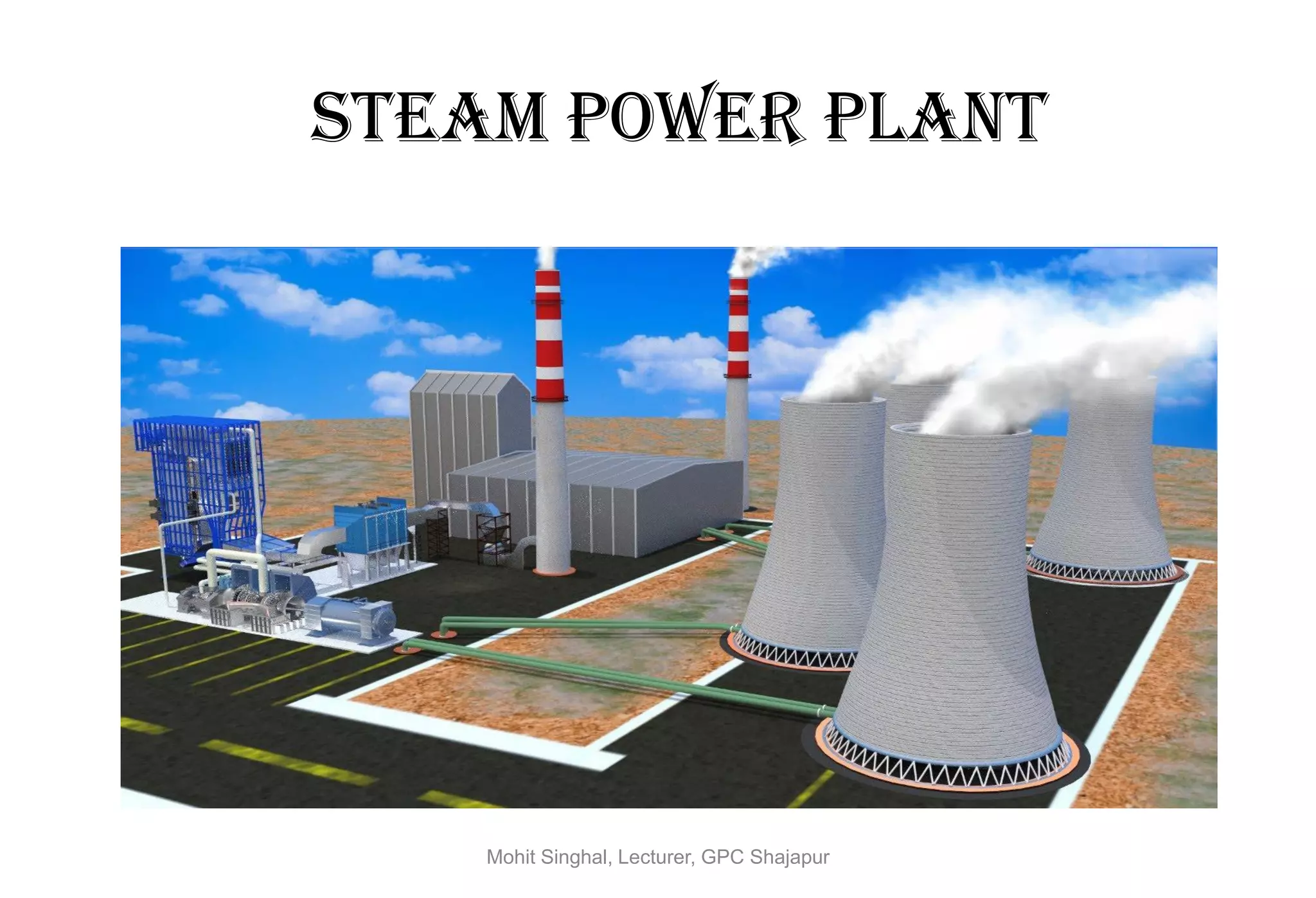
STEAM POWER PLANT
Mohit Singhal, Lecturer, GPC Shajapur
RATIONALE
• The power demand in the country is increasing at a very fast
pace. In fact, power production is not able to keep pace with the
demand.
• More and more steam power plants are coming up in the public
sector.
• Nuclear Power plants and gas turbine power plants are also
being set up.
• Also industries in public and private sectors are being permitted
to establish their own captive steam and diesel power plants.
• This course is aimed at providing knowledge about the systems
of power generation, and the principles of the equipments.
Mohit Singhal, Lecturer, GPC Shajapur
POWER PLANT
STATION
ULTIMATE AIM OF POWER PLANT
Energy ( Heat / Nuclear/
Hydro / Wind ) Electrical Energy
Mohit Singhal, Lecturer, GPC Shajapur
Classification of Power Plant
Power plants using Non-conventional
(renewable) sources of energy
• Solar thermal power plant
• Wind powered generation (Aero Generation)
• Tidal power plant
• Geothermal power plant
• Bio-mass power plant
• Ocean thermal power plant
•Hydro-Electric power plant
Power plants using conventional
(non-renewable) sources of energy
• Steam power plant
• Nuclear (Atomic) power plant
• Diesel power plant
• Gas power plant
Mohit Singhal, Lecturer, GPC Shajapur
THERMAL
PLANT
STATION
ULTIMATE AIM OF THERMAL POWER PLANT
Heat Energy Electrical Energy
Mohit Singhal, Lecturer, GPC Shajapur
INTRODUCTION
• A Thermal (Steam) Power Plant converts the heat energy of
coal into Electrical Energy. Coal is burnt in a boiler which
converts water into steam. The expansion of steam in
turbine produces Mechanical Power which drives the
alternator coupled to the turbine. Thermal Power Plants
contribute maximum to the generation of Power for any
country.
• Thermal Power Plants constitute 66.2% of the total installed
captive and non-captive power generation in India.
• In thermal generating stations, coal, oil & natural gas etc. are
employed as primary sources of energy.
Mohit Singhal, Lecturer, GPC Shajapur
General Layout Of Thermal Power Plant
Mohit Singhal, Lecturer, GPC Shajapur
Main and Auxiliary Equipments
• Pulverizing plant
• Coal handling plant
• Draft fans
• Boiler
• Ash handling plant
• Turbine
• Condenser
• Cooling towers and ponds
• Feed water Pump
• Economizer
• Superheated and Reheated
• Air preheated
Mohit Singhal, Lecturer, GPC Shajapur
BOILER
Air
Fuel Boiler
DryerAir compressorAtmospheric Air
1. Water tube Boiler A boiler in which water circulates in tubes heated externally by the fire.
2. Fire tube Boiler Water is present in the drum inside the boiler and Hot air is circulated around
maintain the temperature.
Feed Water
(High Pressure & Low
Temperature ) Approx. 170 bar
Super Saturated
Steam ( High Pr.
& High Temp. )
Approx. 170 bar
& 550
Process in the Boiler
:- Heat Addition at
Constant Pressure
Mohit Singhal, Lecturer, GPC Shajapur
TURBINE
In a Thermal Power Plant generally 3 turbines are used to increase the efficiency.
• High Pressure Turbine(HPT): The superheated steam is directly fed to this turbine to rotate it.
• Intermediate Pressure Turbine(IPT): The out put from the HPT is reheated in a reheated(RH) and
used to rotate IPT .
• Low Pressure Turbine(LPT): The Exhausted steam from the IPT is directly fed to rotate the shaft of
LPT.
Condenser
HPT IPT LPT
RH
Super Heated Steam
Super
Heater
Generator
Steam
Shaft
Process in Steam Turbine :
Reversible Adiabatic
Expansion / Isentropic
Mohit Singhal, Lecturer, GPC Shajapur
CONDENSER
• Steam after rotating
steam turbine comes
to condenser.
Condenser refers
here to the shell and
tube heat exchanger
(or surface
condenser) installed
at the outlet of
steam turbine.
Process in Condenser :
Heat Rejection At Constant Pressure
Mohit Singhal, Lecturer, GPC Shajapur
Boiler Feed Water Pump
Cross-Sectional View of PumpProcess in Feed Water Pump:
Reversible Adiabatic Compression /
Isentropic Compression
Mohit Singhal, Lecturer, GPC Shajapur
Simple Rankine / Simple Vapor Power Cycle
T
2 3
41
P
v
1
2 3
4
Boiler
Turbine
Compressor
(pump)
Heat exchanger
(Condenser)
1
2 3
4
Qout
Qin
Wout
Win
SMohit Singhal, Lecturer, GPC Shajapur
Limitation Of Simple Rankine Cycle
1. To avoid transporting and compressing two-phase fluid:
• We can try to condense all fluid exiting from the turbine into
saturated liquid before compressed it by a pump.
1. When the saturated vapor enters the turbine, as its temperature and
pressure decreases, condensation occurs, leading to liquid. These liquid
droplets can significantly damage the turbine blades due to corrosion
and/or erosion.
• One possible solution: superheating the vapor.
• It can also increase the thermal efficiency of the cycle (since TH ).
Mohit Singhal, Lecturer, GPC Shajapur
Modified Rankine cycle
T
s
3
41
2
Boiler
Turbine(pump)
Heat exchanger
(Condenser)
1
2 3
4
Qout
Qin
Wout
Win
Mohit Singhal, Lecturer, GPC Shajapur
Ideal Rankine Cycle - Energy analysis
• Assumptions: steady flow process, No heat generation due to friction,
neglect KE and PE changes for all four devices,
• Apply First Law of Thermodynamics in each process:
(Net heat transfer ) = (Net work out) + (Net Energy flow)
 (qout - qin) = (Wout - Win) + (hout - hin)
• 1-2: Pump (q=0)
 Wpump = h2 - h1 = v(P2-P1)
• 2-3: Boiler (W=0)  qin = h3 - h2
• 3-4: Turbine (q=0)  Wout = h3 - h4
• 4-1: Condenser (W=0)  qout = h4 - h1
Thermal efficiency h = Wnet/qin = 1 - qout/qin = 1 - (h4-h1)/(h3-h2)
Wnet = Wout - Win = (h3-h4) - (h2-h1)
T
s
3
41
2
Mohit Singhal, Lecturer, GPC Shajapur
Thermal Efficiency – How to enhance it?
Thermal efficiency can be improved by manipulating the temperatures and/or pressures in
various components
(a) Lowering the condensing pressure (lowers TL, but decreases quality, x4 )
(b) Superheating the steam to a higher temperature (increases TH but requires
higher temp. materials)
(c) Increasing the boiler pressure (increases TH but requires higher temp. & high
pressure bearable materials)
T
s
1
2
3
4
(a) lower pressure(temp)
s
T
1
2
(b) Superheating
(c) increase pressure
s
T
1
2
3
4
Low quality
high moisture content
1
2
4
Red area = increase in W net
Blue area = decrease in W net
Mohit Singhal, Lecturer, GPC Shajapur
Reheating
• The optimal way of increasing the boiler pressure without increasing the
moisture content in the exiting vapor is to reheat the vapor after it exits from
a first-stage turbine and redirect this reheated vapor into a second turbine.
boiler
high-P
turbine
Low-P
turbine
pump
condenser
1
2
3
4
5
6
T
s
1
2
3 5
6
4
high-P
turbine
low-P
turbine
4
Mohit Singhal, Lecturer, GPC Shajapur
Regeneration
• From 2-2’, the average temperature is very low, therefore, the heat
addition process is at a lower temperature and therefore, the thermal
efficiency is lower. Why?
• Use a regenerator to heat the liquid (feedwater) leaving the pump before
sending it to the boiler. This increases the average temperature during
heat addition in the boiler, hence it increases efficiency.
T
s
1
2
2’
3
4
Lower temp.
heat addition
T
s
1
2
3
4
5
6
7
Use regenerator to heat up the feedwater
higher temp.
heat addition
Extract steam @ 6
From turbine to provide
heat source in the
regenerator
Mohit Singhal, Lecturer, GPC Shajapur

Steam power plant

  • 1.
    STEAM POWER PLANT MohitSinghal, Lecturer, GPC Shajapur
  • 2.
    RATIONALE • The powerdemand in the country is increasing at a very fast pace. In fact, power production is not able to keep pace with the demand. • More and more steam power plants are coming up in the public sector. • Nuclear Power plants and gas turbine power plants are also being set up. • Also industries in public and private sectors are being permitted to establish their own captive steam and diesel power plants. • This course is aimed at providing knowledge about the systems of power generation, and the principles of the equipments. Mohit Singhal, Lecturer, GPC Shajapur
  • 3.
    POWER PLANT STATION ULTIMATE AIMOF POWER PLANT Energy ( Heat / Nuclear/ Hydro / Wind ) Electrical Energy Mohit Singhal, Lecturer, GPC Shajapur
  • 4.
    Classification of PowerPlant Power plants using Non-conventional (renewable) sources of energy • Solar thermal power plant • Wind powered generation (Aero Generation) • Tidal power plant • Geothermal power plant • Bio-mass power plant • Ocean thermal power plant •Hydro-Electric power plant Power plants using conventional (non-renewable) sources of energy • Steam power plant • Nuclear (Atomic) power plant • Diesel power plant • Gas power plant Mohit Singhal, Lecturer, GPC Shajapur
  • 5.
    THERMAL PLANT STATION ULTIMATE AIM OFTHERMAL POWER PLANT Heat Energy Electrical Energy Mohit Singhal, Lecturer, GPC Shajapur
  • 6.
    INTRODUCTION • A Thermal(Steam) Power Plant converts the heat energy of coal into Electrical Energy. Coal is burnt in a boiler which converts water into steam. The expansion of steam in turbine produces Mechanical Power which drives the alternator coupled to the turbine. Thermal Power Plants contribute maximum to the generation of Power for any country. • Thermal Power Plants constitute 66.2% of the total installed captive and non-captive power generation in India. • In thermal generating stations, coal, oil & natural gas etc. are employed as primary sources of energy. Mohit Singhal, Lecturer, GPC Shajapur
  • 7.
    General Layout OfThermal Power Plant Mohit Singhal, Lecturer, GPC Shajapur
  • 8.
    Main and AuxiliaryEquipments • Pulverizing plant • Coal handling plant • Draft fans • Boiler • Ash handling plant • Turbine • Condenser • Cooling towers and ponds • Feed water Pump • Economizer • Superheated and Reheated • Air preheated Mohit Singhal, Lecturer, GPC Shajapur
  • 9.
    BOILER Air Fuel Boiler DryerAir compressorAtmosphericAir 1. Water tube Boiler A boiler in which water circulates in tubes heated externally by the fire. 2. Fire tube Boiler Water is present in the drum inside the boiler and Hot air is circulated around maintain the temperature. Feed Water (High Pressure & Low Temperature ) Approx. 170 bar Super Saturated Steam ( High Pr. & High Temp. ) Approx. 170 bar & 550 Process in the Boiler :- Heat Addition at Constant Pressure Mohit Singhal, Lecturer, GPC Shajapur
  • 10.
    TURBINE In a ThermalPower Plant generally 3 turbines are used to increase the efficiency. • High Pressure Turbine(HPT): The superheated steam is directly fed to this turbine to rotate it. • Intermediate Pressure Turbine(IPT): The out put from the HPT is reheated in a reheated(RH) and used to rotate IPT . • Low Pressure Turbine(LPT): The Exhausted steam from the IPT is directly fed to rotate the shaft of LPT. Condenser HPT IPT LPT RH Super Heated Steam Super Heater Generator Steam Shaft Process in Steam Turbine : Reversible Adiabatic Expansion / Isentropic Mohit Singhal, Lecturer, GPC Shajapur
  • 11.
    CONDENSER • Steam afterrotating steam turbine comes to condenser. Condenser refers here to the shell and tube heat exchanger (or surface condenser) installed at the outlet of steam turbine. Process in Condenser : Heat Rejection At Constant Pressure Mohit Singhal, Lecturer, GPC Shajapur
  • 12.
    Boiler Feed WaterPump Cross-Sectional View of PumpProcess in Feed Water Pump: Reversible Adiabatic Compression / Isentropic Compression Mohit Singhal, Lecturer, GPC Shajapur
  • 13.
    Simple Rankine /Simple Vapor Power Cycle T 2 3 41 P v 1 2 3 4 Boiler Turbine Compressor (pump) Heat exchanger (Condenser) 1 2 3 4 Qout Qin Wout Win SMohit Singhal, Lecturer, GPC Shajapur
  • 14.
    Limitation Of SimpleRankine Cycle 1. To avoid transporting and compressing two-phase fluid: • We can try to condense all fluid exiting from the turbine into saturated liquid before compressed it by a pump. 1. When the saturated vapor enters the turbine, as its temperature and pressure decreases, condensation occurs, leading to liquid. These liquid droplets can significantly damage the turbine blades due to corrosion and/or erosion. • One possible solution: superheating the vapor. • It can also increase the thermal efficiency of the cycle (since TH ). Mohit Singhal, Lecturer, GPC Shajapur
  • 15.
    Modified Rankine cycle T s 3 41 2 Boiler Turbine(pump) Heatexchanger (Condenser) 1 2 3 4 Qout Qin Wout Win Mohit Singhal, Lecturer, GPC Shajapur
  • 16.
    Ideal Rankine Cycle- Energy analysis • Assumptions: steady flow process, No heat generation due to friction, neglect KE and PE changes for all four devices, • Apply First Law of Thermodynamics in each process: (Net heat transfer ) = (Net work out) + (Net Energy flow)  (qout - qin) = (Wout - Win) + (hout - hin) • 1-2: Pump (q=0)  Wpump = h2 - h1 = v(P2-P1) • 2-3: Boiler (W=0)  qin = h3 - h2 • 3-4: Turbine (q=0)  Wout = h3 - h4 • 4-1: Condenser (W=0)  qout = h4 - h1 Thermal efficiency h = Wnet/qin = 1 - qout/qin = 1 - (h4-h1)/(h3-h2) Wnet = Wout - Win = (h3-h4) - (h2-h1) T s 3 41 2 Mohit Singhal, Lecturer, GPC Shajapur
  • 17.
    Thermal Efficiency –How to enhance it? Thermal efficiency can be improved by manipulating the temperatures and/or pressures in various components (a) Lowering the condensing pressure (lowers TL, but decreases quality, x4 ) (b) Superheating the steam to a higher temperature (increases TH but requires higher temp. materials) (c) Increasing the boiler pressure (increases TH but requires higher temp. & high pressure bearable materials) T s 1 2 3 4 (a) lower pressure(temp) s T 1 2 (b) Superheating (c) increase pressure s T 1 2 3 4 Low quality high moisture content 1 2 4 Red area = increase in W net Blue area = decrease in W net Mohit Singhal, Lecturer, GPC Shajapur
  • 18.
    Reheating • The optimalway of increasing the boiler pressure without increasing the moisture content in the exiting vapor is to reheat the vapor after it exits from a first-stage turbine and redirect this reheated vapor into a second turbine. boiler high-P turbine Low-P turbine pump condenser 1 2 3 4 5 6 T s 1 2 3 5 6 4 high-P turbine low-P turbine 4 Mohit Singhal, Lecturer, GPC Shajapur
  • 19.
    Regeneration • From 2-2’,the average temperature is very low, therefore, the heat addition process is at a lower temperature and therefore, the thermal efficiency is lower. Why? • Use a regenerator to heat the liquid (feedwater) leaving the pump before sending it to the boiler. This increases the average temperature during heat addition in the boiler, hence it increases efficiency. T s 1 2 2’ 3 4 Lower temp. heat addition T s 1 2 3 4 5 6 7 Use regenerator to heat up the feedwater higher temp. heat addition Extract steam @ 6 From turbine to provide heat source in the regenerator Mohit Singhal, Lecturer, GPC Shajapur
  • 20.
  • 21.