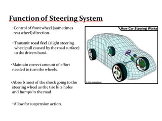
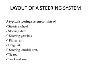
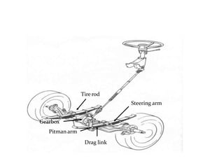
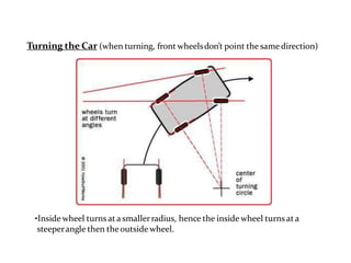
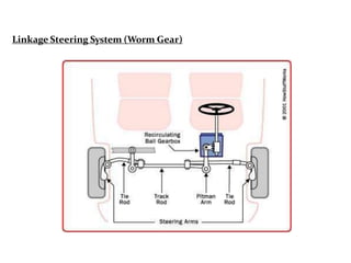
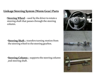
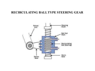
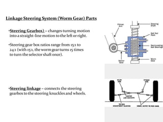
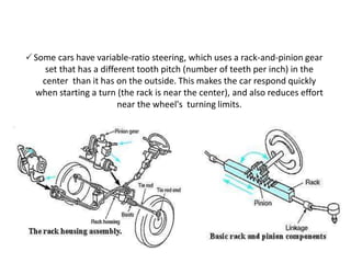
STEERING SYSTEM
STEERING SYSTEM
 Steering is the term applied to the collection of components,
linkages, etc. which will allow a vehicle to follow the desired
direction.
 An automobile is steered with the help of steering gears and
linkages, which transfer the motion of the hand operated
steering wheel to the pivoted front wheel hubs via steering
column.
 The other parts that are used for steering a vehicle are steering
wheel pads, steering shafts, steering boxes, steering arms and
steering stabilizers. These parts are made of durable materials
like stainless steel, iron, aluminum, copper, magnesium,
titanium, platinum, rubber, and plastics.
NEEDS OF STEERING SYSTEM
 It should multiply the turning effort applied on the steering
wheel by the driver.
 It should be to a certain extent irreversible. In other words, the
shocks of the road surface encountered by the wheels should
not be transmitted to the driver’s hands.
 The mechanism should have self rightening effect i.e., when the
driver releases the steering wheel after negotiating the turn, the
wheel should try to achieve straight ahead position.
Functionof Steering System
•Control of front wheel (sometimes
rearwheel) direction.
• Transmit road feel (slight steering
wheel pull caused by the road surface)
to thedrivers hand.
•Maintain correctamount of effort
needed to turn thewheels.
•Absorb mostof theshock going to the
steering wheel as the tire hits holes
and bumps in the road.
•Allow for suspensionaction.
LAYOUT OF A STEERING SYSTEM
A typical steering systemconsistsof
Steering wheel
Steering shaft
 Steering gear box
 Pitman arm
Drag link
 Steering knuckle arm,
Tie rod
Track rod arm
Tire rod
Steering arm
Gearbox
Pitman arm
Drag link
Turning the Car (when turning, front wheelsdon’t point the same direction)
•Inside wheel turns at a smallerradius, hence the inside wheel turns at a
steeperangle then theoutside wheel.
Linkage Steering System (Worm Gear)
Linkage Steering System (Worm Gear) Parts
•Steering Wheel – used by thedriver to rotatea
steering shaft that passes through the steering
column.
•Steering Shaft – transfers turning motion from
thesteering wheel to the steering gearbox.
•Steering Column – supports the steering column
and steering shaft.
STEERING GEARS
 The steering gear is a device for converting the rotary motion
of the steering wheel into straight line motion of the linkage
with a mechanical advantage.
 If the steering wheel is connected directly to the steering
linkage it would require a great effort to move the front
wheels. Therefore, to assist the driver, a reduction system is
used having a steering ratio.
Most useful steering gear system are as follows:
1) Recirculation ball type steering gear.
2) Rack-and-pinion steering.
3) Hydraulic power steering.
RECIRCULATING BALL TYPE
STEERING GEAR
🗸It consists of a worm at the end of steering rod. A nut is mounted on the
worm with two sets of balls is the grooves of the worm, in between the nut
and, the worm. The balls reduce the friction during the movement of the nut
on the worm. The nut has a number of teeth on outside, which mesh with
the teeth on a worm wheel sector, on which is further mounted the drop arm.
🗸When the steering wheel is turned, the balls in the worm roll in the grooves
and cause the nut to travel along the length of the worm. The balls, which
are in 2 sets, are recirculated through the guides. The movement of the nut
causes the wheel sector to turn at an angle and actuate the link rod through
the drop arm, resulting in the desired steering of the wheels. The end play of
the worm can be adjusted by means of the adjuster nut provided.
🗸To compensate for the wear of the teeth on the nut and the worm, the two
have to be brought nearer bodily. To achieve this, the teeth on the nut are
made tapered in the plane perpendicular to the plane of Figure.
RECIRCULATING BALLTYPE STEERING GEAR
Linkage Steering System (Worm Gear) Parts
•Steering Gearbox) – changes turning motion
into a straight-line motion to the leftorright.
•Steering gear box ratios range from 15:1 to
24:1 (with 15:1, thewormgearturns 15 times
to turn theselectorshaftonce).
•Steering linkage – connects the steering
gearboxto thesteering knucklesand wheels.
RACK-AND-PINION STEERING
 Rack-and-pinion steering is quickly becoming the most common type of
steering on cars, small trucks and SUVs.
The rack-and-pinion gear set does two things:
 It converts the rotational motion of the steering wheel into the linear motion
needed to turn the wheels.
 It provides a gear reduction, making it easier to turn the wheels.
 Arack-and-pinion gear set is enclosed in a metal tube, with each end of the
rack protruding from the tube. A rod, called a tie rod, connects to each end
of the rack. The pinion gear is attached to the steering shaft. When you turn
the steering wheel, the gear spins, moving the rack. The tie rod at each end
of the rack connects to the steering arm on the spindle.
🗸Some cars have variable-ratio steering, which uses a rack-and-pinion gear
set that has a different tooth pitch (number of teeth per inch) in the
center than it has on the outside. This makes the car respond quickly
when starting a turn (the rack is near the center), and also reduces effort
near the wheel's turning limits.
Basic Rack-and-Pinion Steering
•Pinion Gear- rotated by the steering wheel and steering shaft; it’s teeth mesh
with the teeth on the rack.
•Rack- long steel barwith teeth along one section; slides sidewaysas the pinion
gearturns.
Basic Rack-and-Pinion Steering
•GearHousing- holds thepinion
gearand rack.
•Tie-rods- connects the rack with
steering knuckles.
Basic Rack-and-Pinion Steering
•Partof rack contains a piston
•Two fluid ports, one on each side.
•Thesidewith high pressurepushes the piston to the
oppositeside (turning thewheel).
Steering Linkage
Pitman Arm transfersgearbox motion to thesteering linkage.
•Pitman arm is splined to thegearbox.
Steering Linkage
Center Link (Relay Rod) steel barconnects the rightand
left side of the steering linkage.
•Connects to Pitman arm, Tie rod ends, and Idlerarm.
Steering Linkage
IdlerArm supports theend of thecenter link on
the passengersideof thevehicle.
•Bolts to thevehicle’s frame.
•If worn, will causeexcessive steering play.
Steering Linkage
Tie-Rod Assemblies: Two tie-rod assembliesare used
to fasten thecenter link tosteering knuckles.
•Assemblyis consist of inner tie-rod end, outer tie-rod end,
and a toeadjustment sleeve.
•Be sure tocheck the toe setting after replacing the
tie-rod ends.
Steering Linkage
Rack-and-pinion outer tie-rod end is similar to
the regular tie-rod end, but the inner tie-rod end
sits inside the rack assembly.
⚫ HYDRAULIC POWER STEERING : is a hydraulic system for reducing
the steering effort on vehicles by using hydraulic pressure to assist in
turning the wheels. It is intended to provide for easier driving direction
control of the car while preserving "feedback", stability and unambiguity of
the trajectory specified. The steering booster is arranged so that should the
booster fail, the steering will continue to work (although the wheel will feel
heavier).
The steering booster consists of the following basic elements:
🗸Steer torque detector
🗸Controlled pressure distributor case
🗸Hydraulic booster pump
🗸Tank with a working liquid
🗸Connection hoses
The working liquid, also called "hydraulic fluid" or "oil", is the medium by
which pressure is transmitted. Common working liquids are based on
mineral oil. For pressure restriction in the pump there is a restrictive valve,
which is adjusted on different cars in a range from 7 to 13 MPa.
HYDRAULIC POWER STEERING
Power Steering normally usean engine driven pump and a hydraulic
system toassiststeering action.
Three majortypes of powersteering systems:
•Integral-piston linkage system.
•External powersteering system.
•Rack-and-pinion system
•Integral power piston.
•External power piston.
Integral Rack-and-pinion system
is the mostcommon.
Powersteering pump is driven by theengine produces the hydraulic
pressure forsteering systemoperation.
Four basicpumps:
•Rollerpump.
•Vane pump.
•Slipper pump.
•Gearpump.
Steering System Diagnosis
Steering Wheel Play is the mostcommon problem.
Should not beable to turn thesteering wheel
more than 1 ½’’ (33mm) without causing
movement of the front wheels.
Move thewheel side-to-side,
should have no play.
Steering System Diagnosis
Hard Steering (steering wheel requires excessive turning effort)
•Low powersteering fluid.
•Pump belt brokenorslipping.
Steering System Noise
•Belt squeal is a loud screeching sound produced byaworn belt.
•Power steering pump noise is usuallya loud whine that onlyoccurswhen
thesteering wheel is turned.
•Low fluid level and air in the system.
Check fluid with engine turned off.
◾CASTER ANGLE
◾CAMBER ANGLE
◾STEERING AXIS INCLINATION
◾TOE
◾THRUST ANGLE
◾TURNING RADIUS
◾SUSPENSION HEIGHT
CASTER ANGLE
Angle between vertical line and
centre line of king pin
FUNCTIONS
◾ SELF CENTRING
ACTION
◾ STRAIGHT LINE
STABILITY
◾ EXCESSIVE CASTER
MAKES STEERING
HEAVIER, LESS
RESPONSIVE AND
INCREASED EFFORT
FUNCTIONS
◾ +VE CAMER LOWER
STEERING EFFORT
◾ -VE CAMBER
IMPROVES GRIP
◾ EXCESSIVE CAMBER
CAUSES INCREASED
TIRE WEAR, REDUCES
STRAIGT LINE
ACCLERATION
Inward and outward lilt
of wheel (from F.V.)
CAMBER ANGLE
ANGLE BETWEEN VERTICLE LINE AND
KINGPIN CENTRE LINE (From F.V.)
FUNCTIONS
◾ HELPS IN
STEERING
RETURNABILITY
AFTER A TURN IS
COMPLETED
◾ REDUCES
STEERING EFFORT
◾ REDUCES TIRE
WEAR
SYMMETERICANGLE B/W
WHEELSANDAXISOFVEHICLE
 TOE IN INCREASES
STRAIGHT LINE
STABILITY AT
COST OF TURNING
RESPONSE
 GREATER THE TOE
FASTER THE TIRE
WEARS
FUNCTIONS
TOE-IN TOE-OUT
Angle between Geometric line
and Thrust Line
◾ OCCURS WHEN REAR
WHEEL HAS
IMPROPER
ALIGNMENT
◾ EFFECTS DIRECTION
OF TRAVEL BY
CAUSING PULL IN THE
DIRECTION AWAY
FROM THRUST LINE
FUNCTIONS
Turning circle radius = (track/2) + (wheelbase/
sin(average steer angle))
The turning circle of a car is the diameter
of the circle described by the outside
wheels when turning on full lock.
◾ SYSTEM AUTOMATICALLY STEERS THE REAR
WHEELS ACCORDING TO SPEED OF VEHICLE
AND STEERING ANGLE.
◾ USED IN MILITARY, OFF ROAD VEHICLES,
BUSES, TRUCKS AND LARGE VAHICLS
◾ INCREASES HANDLING AND
STABILITY
◾ REDUCES TURNING RADIUS
◾ VEHICLE STEERS BY POWER ASSIST
FROM EXTERNAL SOURCE OTHER
THAN DRIVER’S EFFORT
◾ HELPS IN STEERING OF HEAVY
VEHICLES
◾ INCREASES THE STEERING RATIO
AND REDUCES DRIVER’S EFFORT
◾ TWO MAJOR TYPES – HPS AND EPS
unit 3 Steering System.pptx

unit 3 Steering System.pptx

  • 1.
  • 2.
    STEERING SYSTEM  Steeringis the term applied to the collection of components, linkages, etc. which will allow a vehicle to follow the desired direction.  An automobile is steered with the help of steering gears and linkages, which transfer the motion of the hand operated steering wheel to the pivoted front wheel hubs via steering column.  The other parts that are used for steering a vehicle are steering wheel pads, steering shafts, steering boxes, steering arms and steering stabilizers. These parts are made of durable materials like stainless steel, iron, aluminum, copper, magnesium, titanium, platinum, rubber, and plastics.
  • 3.
    NEEDS OF STEERINGSYSTEM  It should multiply the turning effort applied on the steering wheel by the driver.  It should be to a certain extent irreversible. In other words, the shocks of the road surface encountered by the wheels should not be transmitted to the driver’s hands.  The mechanism should have self rightening effect i.e., when the driver releases the steering wheel after negotiating the turn, the wheel should try to achieve straight ahead position.
  • 4.
    Functionof Steering System •Controlof front wheel (sometimes rearwheel) direction. • Transmit road feel (slight steering wheel pull caused by the road surface) to thedrivers hand. •Maintain correctamount of effort needed to turn thewheels. •Absorb mostof theshock going to the steering wheel as the tire hits holes and bumps in the road. •Allow for suspensionaction.
  • 5.
    LAYOUT OF ASTEERING SYSTEM A typical steering systemconsistsof Steering wheel Steering shaft  Steering gear box  Pitman arm Drag link  Steering knuckle arm, Tie rod Track rod arm
  • 6.
  • 7.
    Turning the Car(when turning, front wheelsdon’t point the same direction) •Inside wheel turns at a smallerradius, hence the inside wheel turns at a steeperangle then theoutside wheel.
  • 8.
  • 9.
    Linkage Steering System(Worm Gear) Parts •Steering Wheel – used by thedriver to rotatea steering shaft that passes through the steering column. •Steering Shaft – transfers turning motion from thesteering wheel to the steering gearbox. •Steering Column – supports the steering column and steering shaft.
  • 10.
    STEERING GEARS  Thesteering gear is a device for converting the rotary motion of the steering wheel into straight line motion of the linkage with a mechanical advantage.  If the steering wheel is connected directly to the steering linkage it would require a great effort to move the front wheels. Therefore, to assist the driver, a reduction system is used having a steering ratio. Most useful steering gear system are as follows: 1) Recirculation ball type steering gear. 2) Rack-and-pinion steering. 3) Hydraulic power steering.
  • 11.
    RECIRCULATING BALL TYPE STEERINGGEAR 🗸It consists of a worm at the end of steering rod. A nut is mounted on the worm with two sets of balls is the grooves of the worm, in between the nut and, the worm. The balls reduce the friction during the movement of the nut on the worm. The nut has a number of teeth on outside, which mesh with the teeth on a worm wheel sector, on which is further mounted the drop arm. 🗸When the steering wheel is turned, the balls in the worm roll in the grooves and cause the nut to travel along the length of the worm. The balls, which are in 2 sets, are recirculated through the guides. The movement of the nut causes the wheel sector to turn at an angle and actuate the link rod through the drop arm, resulting in the desired steering of the wheels. The end play of the worm can be adjusted by means of the adjuster nut provided. 🗸To compensate for the wear of the teeth on the nut and the worm, the two have to be brought nearer bodily. To achieve this, the teeth on the nut are made tapered in the plane perpendicular to the plane of Figure.
  • 12.
  • 13.
    Linkage Steering System(Worm Gear) Parts •Steering Gearbox) – changes turning motion into a straight-line motion to the leftorright. •Steering gear box ratios range from 15:1 to 24:1 (with 15:1, thewormgearturns 15 times to turn theselectorshaftonce). •Steering linkage – connects the steering gearboxto thesteering knucklesand wheels.
  • 14.
    RACK-AND-PINION STEERING  Rack-and-pinionsteering is quickly becoming the most common type of steering on cars, small trucks and SUVs. The rack-and-pinion gear set does two things:  It converts the rotational motion of the steering wheel into the linear motion needed to turn the wheels.  It provides a gear reduction, making it easier to turn the wheels.  Arack-and-pinion gear set is enclosed in a metal tube, with each end of the rack protruding from the tube. A rod, called a tie rod, connects to each end of the rack. The pinion gear is attached to the steering shaft. When you turn the steering wheel, the gear spins, moving the rack. The tie rod at each end of the rack connects to the steering arm on the spindle.
  • 15.
    🗸Some cars havevariable-ratio steering, which uses a rack-and-pinion gear set that has a different tooth pitch (number of teeth per inch) in the center than it has on the outside. This makes the car respond quickly when starting a turn (the rack is near the center), and also reduces effort near the wheel's turning limits.
  • 16.
  • 17.
    Basic Rack-and-Pinion Steering •PinionGear- rotated by the steering wheel and steering shaft; it’s teeth mesh with the teeth on the rack. •Rack- long steel barwith teeth along one section; slides sidewaysas the pinion gearturns.
  • 18.
    Basic Rack-and-Pinion Steering •GearHousing-holds thepinion gearand rack. •Tie-rods- connects the rack with steering knuckles.
  • 19.
    Basic Rack-and-Pinion Steering •Partofrack contains a piston •Two fluid ports, one on each side. •Thesidewith high pressurepushes the piston to the oppositeside (turning thewheel).
  • 20.
    Steering Linkage Pitman Armtransfersgearbox motion to thesteering linkage. •Pitman arm is splined to thegearbox.
  • 21.
    Steering Linkage Center Link(Relay Rod) steel barconnects the rightand left side of the steering linkage. •Connects to Pitman arm, Tie rod ends, and Idlerarm.
  • 22.
    Steering Linkage IdlerArm supportstheend of thecenter link on the passengersideof thevehicle. •Bolts to thevehicle’s frame. •If worn, will causeexcessive steering play.
  • 23.
    Steering Linkage Tie-Rod Assemblies:Two tie-rod assembliesare used to fasten thecenter link tosteering knuckles. •Assemblyis consist of inner tie-rod end, outer tie-rod end, and a toeadjustment sleeve. •Be sure tocheck the toe setting after replacing the tie-rod ends.
  • 24.
    Steering Linkage Rack-and-pinion outertie-rod end is similar to the regular tie-rod end, but the inner tie-rod end sits inside the rack assembly.
  • 25.
    ⚫ HYDRAULIC POWERSTEERING : is a hydraulic system for reducing the steering effort on vehicles by using hydraulic pressure to assist in turning the wheels. It is intended to provide for easier driving direction control of the car while preserving "feedback", stability and unambiguity of the trajectory specified. The steering booster is arranged so that should the booster fail, the steering will continue to work (although the wheel will feel heavier). The steering booster consists of the following basic elements: 🗸Steer torque detector 🗸Controlled pressure distributor case 🗸Hydraulic booster pump 🗸Tank with a working liquid 🗸Connection hoses The working liquid, also called "hydraulic fluid" or "oil", is the medium by which pressure is transmitted. Common working liquids are based on mineral oil. For pressure restriction in the pump there is a restrictive valve, which is adjusted on different cars in a range from 7 to 13 MPa. HYDRAULIC POWER STEERING
  • 27.
    Power Steering normallyusean engine driven pump and a hydraulic system toassiststeering action. Three majortypes of powersteering systems: •Integral-piston linkage system. •External powersteering system. •Rack-and-pinion system •Integral power piston. •External power piston. Integral Rack-and-pinion system is the mostcommon.
  • 28.
    Powersteering pump isdriven by theengine produces the hydraulic pressure forsteering systemoperation. Four basicpumps: •Rollerpump. •Vane pump. •Slipper pump. •Gearpump.
  • 29.
    Steering System Diagnosis SteeringWheel Play is the mostcommon problem. Should not beable to turn thesteering wheel more than 1 ½’’ (33mm) without causing movement of the front wheels. Move thewheel side-to-side, should have no play.
  • 30.
    Steering System Diagnosis HardSteering (steering wheel requires excessive turning effort) •Low powersteering fluid. •Pump belt brokenorslipping. Steering System Noise •Belt squeal is a loud screeching sound produced byaworn belt. •Power steering pump noise is usuallya loud whine that onlyoccurswhen thesteering wheel is turned. •Low fluid level and air in the system. Check fluid with engine turned off.
  • 31.
    ◾CASTER ANGLE ◾CAMBER ANGLE ◾STEERINGAXIS INCLINATION ◾TOE ◾THRUST ANGLE ◾TURNING RADIUS ◾SUSPENSION HEIGHT
  • 32.
    CASTER ANGLE Angle betweenvertical line and centre line of king pin FUNCTIONS ◾ SELF CENTRING ACTION ◾ STRAIGHT LINE STABILITY ◾ EXCESSIVE CASTER MAKES STEERING HEAVIER, LESS RESPONSIVE AND INCREASED EFFORT
  • 33.
    FUNCTIONS ◾ +VE CAMERLOWER STEERING EFFORT ◾ -VE CAMBER IMPROVES GRIP ◾ EXCESSIVE CAMBER CAUSES INCREASED TIRE WEAR, REDUCES STRAIGT LINE ACCLERATION Inward and outward lilt of wheel (from F.V.) CAMBER ANGLE
  • 34.
    ANGLE BETWEEN VERTICLELINE AND KINGPIN CENTRE LINE (From F.V.) FUNCTIONS ◾ HELPS IN STEERING RETURNABILITY AFTER A TURN IS COMPLETED ◾ REDUCES STEERING EFFORT ◾ REDUCES TIRE WEAR
  • 35.
    SYMMETERICANGLE B/W WHEELSANDAXISOFVEHICLE  TOEIN INCREASES STRAIGHT LINE STABILITY AT COST OF TURNING RESPONSE  GREATER THE TOE FASTER THE TIRE WEARS FUNCTIONS
  • 36.
  • 37.
    Angle between Geometricline and Thrust Line ◾ OCCURS WHEN REAR WHEEL HAS IMPROPER ALIGNMENT ◾ EFFECTS DIRECTION OF TRAVEL BY CAUSING PULL IN THE DIRECTION AWAY FROM THRUST LINE FUNCTIONS
  • 38.
    Turning circle radius= (track/2) + (wheelbase/ sin(average steer angle)) The turning circle of a car is the diameter of the circle described by the outside wheels when turning on full lock.
  • 39.
    ◾ SYSTEM AUTOMATICALLYSTEERS THE REAR WHEELS ACCORDING TO SPEED OF VEHICLE AND STEERING ANGLE. ◾ USED IN MILITARY, OFF ROAD VEHICLES, BUSES, TRUCKS AND LARGE VAHICLS ◾ INCREASES HANDLING AND STABILITY ◾ REDUCES TURNING RADIUS
  • 41.
    ◾ VEHICLE STEERSBY POWER ASSIST FROM EXTERNAL SOURCE OTHER THAN DRIVER’S EFFORT ◾ HELPS IN STEERING OF HEAVY VEHICLES ◾ INCREASES THE STEERING RATIO AND REDUCES DRIVER’S EFFORT ◾ TWO MAJOR TYPES – HPS AND EPS