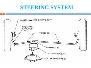
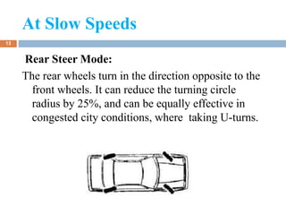
PRESENTATION
ON
“ 360 DEGREE LOAD
CARRIER”
1
Neeraj Gautam (07ME026)
Presented by:
CONTENTS
 INTRODUCTION
 STEERING SYSTEM
 TYPES OF STEERING SYSTEM
 FOUR WHEEL STEERING SYSTEM
 MODES IN 4WS SYSTEM
 STEERING PRINCIPLES AND COMPONENTS
 BENEFITS OF THE 4WS MODEL
2
INTRODUCTION
 The front-to-rear wheel alignment plays a
significant role in the directional stability of a
vehicle.
 Often the lack of stability causes a dangerous
drive.
 Up to the mid-1950s the majority of cars
suffered from over-steer, mainly due to the
uncontrolled movement of the rear axle caused
by spring deflection which is initiated by body
roll.
3
INTRODUCTION Cont..,
4
 To improve stability, most cars nowadays are
designed to exhibit under-steer characteristic
when driven at high speeds.
 Although under-steer condition improves stability
of the vehicle, it increases the driver's steering
effort. Also since a vehicle handling changes with
road speed, the response to a steering movement,
both in time and direction, is difficult to predict.
 These disadvantages can be overcome to a great
extent by using four wheel steering (4WS).
STEERING SYSTEM
5
 Steering of a four wheel vehicle is, as far as
possible, arranged so that the front wheels will roll
truly without any lateral slip.
 The front wheels are supported on front axle so that
they can swing to the left or right for steering.
 This movement is produced by gearing and linkage
between the steering wheel in front of the driver
and the steering knuckle or wheel.
 The complete arrangement is called the steering
system.
STEERING SYSTEM
6
electric power steering
7
electric power steering
REQUREMENTS OF
STEERING SYSTEM
8
 It should multiply the turning effort applied on the
steering wheel by the driver.
 It should be to a certain degree irreversible so that
the shocks of the road surface encountered by the
wheels are not transmitted to the driver’s hand.
 The mechanism should have self –rightening effect
so that when the driver release the steering wheel
after negotiating the turn , the wheel should try to
achieve straight ahead position .
FUNCTIONS OF THE STEERING
SYSTEM
9
 To control the angular motion the wheels and thus
the direction of motion of the vehicle.
 To provide directional stability of the vehicle while
going straight ahead.
 To facilitate straight ahead condition of the vehicle
after completing a turn.
 To minimize tyre wear and increase the life of the
tyres.
TYPES OF STEERING SYSTEM
10
Depending on the number and position of the
wheels being steered , steering systems can be
classified as
 Front wheel steering.
 Rear wheel steering.
 Four wheel steering.
11
Front wheel steering
The two front wheels of the vehicle are used to steer
the vehicle. This type of steering suffers from larger
turning circle and the extra effort required by the
driver to negotiate the turn.
Rear wheel steering
The two rear wheels control the steering. It can
produced smaller turning circles, but is unsuitable
for high speed purposes and for ease of use. Some
types of industry battery trucks.
MODES IN 4WS SYSTEM
12
TWO MODES ARE GENERALLY
USED IN THESE 4WS MODEL
 Slow Speeds - Rear Steer Mode:
 High speeds – Crab Mode.
At Slow Speeds
13
Rear Steer Mode:
The rear wheels turn in the direction opposite to the
front wheels. It can reduce the turning circle
radius by 25%, and can be equally effective in
congested city conditions, where taking U-turns.
High Speeds:
14
In high speeds, turning the rear wheels through an
angle opposite to front wheels might lead to vehicle
instability and is thus unsuitable. Hence, at speeds
above 80 kmph , the rear wheels are turned in the
same direction of front wheels in four-wheel
steering systems.
STEERING PRINCIPLES AND
COMPONENTS
15
ACKERMAN STEERING MECHANISM
 With perfect Ackermann, at any angle of
steering, the centre point of all of the circles traced
by all wheels will lie at a common point. But this
may be difficult to arrange in practice with simple
linkages.
 Hence, modern cars do not use pure
Ackermann steering, partly because it ignores
important dynamic and compliant effects, but the
principle is sound for low speed manoeuvres.
TURNING CIRCLES
16
 The turning circle of a car is the diameter of the
circle described by the outside wheels when turning
on full lock. There is no hard and fast formula to
calculate the turning circle but you can get close by
using this:
Turning circle radius = (track/2) + (wheelbase/
sin(average steer
angle))
King-pin inclination or steering
axle inclination
17
The angle between the
vertical line and centre of
the king pin or steering
axle, when viewed from
the front of the vehicle is
known as king pin
inclination or steering
axle inclination.
CASTOR
18
 In addition to being tilted inward toward the centre
of the vehicle, the kingpin axis may also be tilted
forward or backward from the vertical line. This tilt
is known as caster.
 . Thus the angle between the vertical line and the
kingpin centre line in the plane of the wheel (when
viewed from the side) is called caster angle.
19
CASTOR
CAMBER
20
 The angle between the centre line of the tyre and
the vertical line when viewed from the front of the
vehicle is known as camber.
 Positive camber: When upper part of wheel is
outside.
 Negative camber: When upper part of wheel is
inside (towards the center line of the car)
TOE-IN & TOE-OUT
21
 The front wheels are usually turned in slightly in
front so that the distance between the front ends (a)
is slightly less than the distance between the back
ends (b), when viewed from the top. The difference
between these distances is called toe in.
 Toe-out is the difference in angles between the two
front wheels and the car frame during turns. The
toe-out is secured by providing the proper
relationship between the steering knuckle arms, tie
rods and pitman arm.
TOE-IN & TOE-OUT
22
VEHICLE DYNAMICS AND
STEERING
23
Understeer:
Understeer is so called because when the slip angle
of front wheels is greater than slip angle of rear
wheels.
Oversteer:
Over steer is defined when the slip angle of front
wheels lesser than the slip angle of rear wheels.
Neutral steer or counter steering:
Counter-steering can defined as when the slip angle
of front wheels is equal to slip angle of rear wheels
24
Understeer Oversteer
Neutral steer or
counter steering
WORKING PRINCIPLE
25
 When the steering is steered the power is transferred to the front
steering gear box, and a bevel gear arrangement is made to transfer
the power to the rear steering gear box.
 Bevel gear is used to transmit the rotary motion perpendicularly, so
the one bevel gear is introduced in the front steering rod. Other
bevel gear is connected to the transfer rod.
 Two supports are used to support the transfer rod. Transfer rod is
connected to the rear steering gear box. Rear steering gear box is
fixed to the car body by bolts and nuts and the ends of the steering
box are connected to the rear wheel hub where the tyres are
mounted.
 As the steering is steered the rear wheels also turn by the
arrangements made and the rear wheel turn in the opposite
direction.
BENEFITS OF THE 4WS MODEL
26
 In conjunction with rear steer mode, four-wheel
steering can significantly improve the vehicle
handling at both high and low speeds.
 Due to the better handling and easier steering
capability, driver fatigue can be reduced even over
long drives.
 Stability of the vehicle increases.
 Turning radius of the vehicle can be decreased to a
greater extent by rear steer mode.
THANK
YOU
27
QUERIES…
….
28

360 degree load carrier

  • 1.
    PRESENTATION ON “ 360 DEGREELOAD CARRIER” 1 Neeraj Gautam (07ME026) Presented by:
  • 2.
    CONTENTS  INTRODUCTION  STEERINGSYSTEM  TYPES OF STEERING SYSTEM  FOUR WHEEL STEERING SYSTEM  MODES IN 4WS SYSTEM  STEERING PRINCIPLES AND COMPONENTS  BENEFITS OF THE 4WS MODEL 2
  • 3.
    INTRODUCTION  The front-to-rearwheel alignment plays a significant role in the directional stability of a vehicle.  Often the lack of stability causes a dangerous drive.  Up to the mid-1950s the majority of cars suffered from over-steer, mainly due to the uncontrolled movement of the rear axle caused by spring deflection which is initiated by body roll. 3
  • 4.
    INTRODUCTION Cont.., 4  Toimprove stability, most cars nowadays are designed to exhibit under-steer characteristic when driven at high speeds.  Although under-steer condition improves stability of the vehicle, it increases the driver's steering effort. Also since a vehicle handling changes with road speed, the response to a steering movement, both in time and direction, is difficult to predict.  These disadvantages can be overcome to a great extent by using four wheel steering (4WS).
  • 5.
    STEERING SYSTEM 5  Steeringof a four wheel vehicle is, as far as possible, arranged so that the front wheels will roll truly without any lateral slip.  The front wheels are supported on front axle so that they can swing to the left or right for steering.  This movement is produced by gearing and linkage between the steering wheel in front of the driver and the steering knuckle or wheel.  The complete arrangement is called the steering system.
  • 6.
  • 7.
  • 8.
    REQUREMENTS OF STEERING SYSTEM 8 It should multiply the turning effort applied on the steering wheel by the driver.  It should be to a certain degree irreversible so that the shocks of the road surface encountered by the wheels are not transmitted to the driver’s hand.  The mechanism should have self –rightening effect so that when the driver release the steering wheel after negotiating the turn , the wheel should try to achieve straight ahead position .
  • 9.
    FUNCTIONS OF THESTEERING SYSTEM 9  To control the angular motion the wheels and thus the direction of motion of the vehicle.  To provide directional stability of the vehicle while going straight ahead.  To facilitate straight ahead condition of the vehicle after completing a turn.  To minimize tyre wear and increase the life of the tyres.
  • 10.
    TYPES OF STEERINGSYSTEM 10 Depending on the number and position of the wheels being steered , steering systems can be classified as  Front wheel steering.  Rear wheel steering.  Four wheel steering.
  • 11.
    11 Front wheel steering Thetwo front wheels of the vehicle are used to steer the vehicle. This type of steering suffers from larger turning circle and the extra effort required by the driver to negotiate the turn. Rear wheel steering The two rear wheels control the steering. It can produced smaller turning circles, but is unsuitable for high speed purposes and for ease of use. Some types of industry battery trucks.
  • 12.
    MODES IN 4WSSYSTEM 12 TWO MODES ARE GENERALLY USED IN THESE 4WS MODEL  Slow Speeds - Rear Steer Mode:  High speeds – Crab Mode.
  • 13.
    At Slow Speeds 13 RearSteer Mode: The rear wheels turn in the direction opposite to the front wheels. It can reduce the turning circle radius by 25%, and can be equally effective in congested city conditions, where taking U-turns.
  • 14.
    High Speeds: 14 In highspeeds, turning the rear wheels through an angle opposite to front wheels might lead to vehicle instability and is thus unsuitable. Hence, at speeds above 80 kmph , the rear wheels are turned in the same direction of front wheels in four-wheel steering systems.
  • 15.
    STEERING PRINCIPLES AND COMPONENTS 15 ACKERMANSTEERING MECHANISM  With perfect Ackermann, at any angle of steering, the centre point of all of the circles traced by all wheels will lie at a common point. But this may be difficult to arrange in practice with simple linkages.  Hence, modern cars do not use pure Ackermann steering, partly because it ignores important dynamic and compliant effects, but the principle is sound for low speed manoeuvres.
  • 16.
    TURNING CIRCLES 16  Theturning circle of a car is the diameter of the circle described by the outside wheels when turning on full lock. There is no hard and fast formula to calculate the turning circle but you can get close by using this: Turning circle radius = (track/2) + (wheelbase/ sin(average steer angle))
  • 17.
    King-pin inclination orsteering axle inclination 17 The angle between the vertical line and centre of the king pin or steering axle, when viewed from the front of the vehicle is known as king pin inclination or steering axle inclination.
  • 18.
    CASTOR 18  In additionto being tilted inward toward the centre of the vehicle, the kingpin axis may also be tilted forward or backward from the vertical line. This tilt is known as caster.  . Thus the angle between the vertical line and the kingpin centre line in the plane of the wheel (when viewed from the side) is called caster angle.
  • 19.
  • 20.
    CAMBER 20  The anglebetween the centre line of the tyre and the vertical line when viewed from the front of the vehicle is known as camber.  Positive camber: When upper part of wheel is outside.  Negative camber: When upper part of wheel is inside (towards the center line of the car)
  • 21.
    TOE-IN & TOE-OUT 21 The front wheels are usually turned in slightly in front so that the distance between the front ends (a) is slightly less than the distance between the back ends (b), when viewed from the top. The difference between these distances is called toe in.  Toe-out is the difference in angles between the two front wheels and the car frame during turns. The toe-out is secured by providing the proper relationship between the steering knuckle arms, tie rods and pitman arm.
  • 22.
  • 23.
    VEHICLE DYNAMICS AND STEERING 23 Understeer: Understeeris so called because when the slip angle of front wheels is greater than slip angle of rear wheels. Oversteer: Over steer is defined when the slip angle of front wheels lesser than the slip angle of rear wheels. Neutral steer or counter steering: Counter-steering can defined as when the slip angle of front wheels is equal to slip angle of rear wheels
  • 24.
  • 25.
    WORKING PRINCIPLE 25  Whenthe steering is steered the power is transferred to the front steering gear box, and a bevel gear arrangement is made to transfer the power to the rear steering gear box.  Bevel gear is used to transmit the rotary motion perpendicularly, so the one bevel gear is introduced in the front steering rod. Other bevel gear is connected to the transfer rod.  Two supports are used to support the transfer rod. Transfer rod is connected to the rear steering gear box. Rear steering gear box is fixed to the car body by bolts and nuts and the ends of the steering box are connected to the rear wheel hub where the tyres are mounted.  As the steering is steered the rear wheels also turn by the arrangements made and the rear wheel turn in the opposite direction.
  • 26.
    BENEFITS OF THE4WS MODEL 26  In conjunction with rear steer mode, four-wheel steering can significantly improve the vehicle handling at both high and low speeds.  Due to the better handling and easier steering capability, driver fatigue can be reduced even over long drives.  Stability of the vehicle increases.  Turning radius of the vehicle can be decreased to a greater extent by rear steer mode.
  • 27.
  • 28.