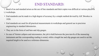
This document discusses factors to consider when selecting measuring instruments, including sensitivity, hysteresis, range, span, response time, repeatability, accuracy, precision, magnification, stability, resolution, error, drift, reliability and more. It describes types of errors such as static errors, dynamic errors, systematic errors and random errors. Methods to reduce errors from the environment, supports, alignment, dirt, vibrations, wear and other sources are provided. The history of measurement standards from ancient Egypt is briefly mentioned.
Line standards and end standards are two categories of instruments used to directly measure linear dimensions.
A line standard measures the distance between the centers of two engraved lines, such as a ruler. It allows for quick measurements over a wide range but lacks precision due to line thickness and susceptibility to parallax errors.
An end standard measures the distance between two parallel flat surfaces, such as slip gauges or a micrometer anvil. It provides highly accurate measurements of close tolerances but is more time-consuming and the faces can wear over time. End standards have a built-in datum for alignment and are not subject to parallax.
This document provides information on various measuring instruments used in manufacturing, including their construction, operation, and proper use. It discusses steel rules, calipers, micrometers, height gauges, and gauge blocks. For Vernier calipers and micrometers, it explains how to take accurate measurements using the main and Vernier scales, and provides examples of calculating total readings. The document emphasizes proper techniques and care for these precision measuring tools.
The document discusses different types of sensors including resistive, capacitive, piezoelectric, magnetic, and strain gauge sensors. It provides details on resistive sensors and their major types like potentiometers, strain gauges, thermistors, and light dependent resistors. The document also describes capacitive sensors, piezoelectric transducers, magnetic sensors like Hall effect sensors, and variable reluctance sensors. Finally, it covers strain gauge sensors, their working, and applications.
Gauge blocks are precision rectangular blocks of high-grade steel used for direct and accurate measurements where precision is required. They were invented in 1896 and are calibrated using a phenomenon called "wringing" for high precision. Gauge blocks are used to calibrate tools like vernier calipers and micrometers, for angle measurement with a sine bar, and to check gaps between parallel locations or mating parts.
Standards of measurement, Historical developments of standards of measurements, material length standard, international yard, international prototype meter, Lightwave or optical length standards, primary standards, secondary standards, tertiary standards, working standards, line standards, end standards,
ME6504 Metrology and measurement unit 1prithiviraj M
The document discusses factors to consider in selecting measurement instruments, including sensitivity, hysteresis, range, span, response time, repeatability, accuracy, precision, and more. It also summarizes various methods of measurement such as direct, indirect, absolute, comparative, transposition, coincidence, deflection, complementary, contact, and contactless methods. The key aspects of a measurement system are to provide information about a physical variable being measured.
Introduction to electrical and electronic measurement system where basics on measurement, units, static and dynamic characteristics of instruments, order of instruments, are discussed in brief. Errors in instrumentation system is discussed. Calibration and traceability of instruments are illustrated.
basic of measurement and instrumentation.SACHINNikam39
This document discusses instrumentation systems and measurement fundamentals. It begins by classifying instrument systems, such as absolute versus secondary instruments, analog versus digital, and mechanical versus electrical versus electronic. It then describes the functional elements of a generalized measurement system, including the primary sensing element, variable conversion element, variable manipulation element, data processing element, data transmission system, and data presentation element. Finally, it discusses standards used for calibration and measurement, categorizing them from primary reference standards to secondary, tertiary, and working standards used in inspection and workshops.
1. The document discusses uncertainties and errors in measurement, distinguishing between systematic and random errors.
2. It describes several methods to determine random errors, including instrument limits of error, estimated uncertainty from repeated measurements, and calculating average and standard deviation.
3. The key points covered are how to calculate uncertainties from measurements, express the range of possible measured values based on the uncertainty, and properly propagate uncertainties through calculations.
This document discusses different types of gauges used for measurement and quality control, including plug gauges, ring gauges, snap gauges, feeler gauges, and limit gauges. It describes the purpose and design of each type of gauge. For example, it states that plug gauges consist of two cylindrical wear-resistant plugs - a GO plug matching the minimum hole size and a NO-GO plug matching the maximum hole size. The document also covers Taylor's principle of gauge design, wear allowance, and includes assignment questions related to gauge design.
1) The document discusses measurement systems and provides definitions for key terms like accuracy, sensitivity, hysteresis, and resolution. It describes analog and digital measurement systems and the components that make them up, including sensors, signal conditioning, and controllers.
2) Common units for physical quantities like length, time, mass and current are discussed as well as standards for measurement. Analog signals like 4-20 mA and 3-15 psi are described for representing variable ranges.
3) Drawings like P&IDs (piping and instrumentation diagrams) and electrical schematics are addressed along with the standards that define their symbols. Sensor response curves are examined, including first-order exponential curves. Tutorial problems are presented at the
This document discusses layout tools and procedures used in construction. It describes common measuring tools like tapes, rules, calipers, and squares used to measure length, width, and other dimensions. These tools can be made of materials like steel, wood, plastic or cloth. Both the U.S. customary and metric systems of measurement are used. The document also outlines tools like levels, which ensure objects are at the same height, as well as patterns, lines, and computers used in layout and design.
This document presents information on the characteristics of instruments. It discusses both static and dynamic characteristics. The main static characteristics described are accuracy, sensitivity, reproducibility, drift, static error, dead zone, precision, threshold, linearity, stability, range/span, bias, tolerance, and hysteresis. The dynamic characteristics covered are speed of response, fidelity, lag, and dynamic error. The document was created by five students and guided by a professor to provide an overview of important instrument characteristics.
very useful ppt for all enginnereing and schoolmstudents.............................................................................................................
Strain gauge load cells work by measuring the strain on an object using electrical resistance strain gauges. When force is applied, the strain gauges experience a change in resistance which is measured by a Wheatstone bridge circuit to produce an electrical output signal proportional to the applied load. The most common type of load cell uses a full Wheatstone bridge configuration with four strain gauges to maximize sensitivity. Proper design considers uniform strain distribution and protection of the gauges. Sources of error include loading errors and environmental effects, which can be compensated for in the design and signal conditioning.
This document provides information about a course on Instrumentation and Process Control taught at Acharya N.G. Ranga Agricultural University. The course aims to impart knowledge of instrumentation and process controls used in the food industry. It covers topics such as measurement principles and methods, different types of instruments, transducers, performance characteristics, and control systems. The course involves both theory lectures and practical exercises where students will learn to use and identify various instruments used in food industry operations.
The bevel protractor can be used to measure both internal and external angles of objects. It has a protractor dial with degree divisions and an attached Vernier scale to allow for precise measurements. To take a measurement, the object is placed between the protractor's sliding and fixed blades. Readings less than 90 degrees are read directly from the dial, while those over 90 degrees require subtracting the dial reading from 180 degrees. The Vernier scale allows measurements to be made with a least count of 5 minutes. Possible sources of error include damage to the instrument, parallax effects, and observer carelessness.
Slip gauges are rectangular blocks made of alloy steel that are used as standards to check the accuracy of measuring instruments. They are hardened, quenched, and superfinished to achieve a very high level of flatness and parallelism on their contact surfaces. Slip gauges are supplied in sets of different sizes so that various length combinations can be obtained through stacking.
The document discusses different types of errors that can occur in measurement. It describes gross errors, systematic errors like instrumental errors and environmental errors, and random errors. It also defines key terms used to analyze errors like limit of reading, greatest possible error, and discusses analyzing measurement data using statistical methods like the mean, standard deviation, variance and histograms. Measurement errors can occur due to issues like parallax, calibration, limits of the measuring device, and are analyzed statistically.
METROLOGY & MEASUREMENT Unit 1 notes (5 files merged)MechRtc
Metrology is the science of measurement. It is concerned with establishing standards of measurement, measuring errors and uncertainties, and ensuring uniformity of measurements. Metrology has applications in industry, commerce, and public health/safety. It functions to maintain standards, train professionals, regulate manufacturers, and conduct research to improve measurement methods and accuracy. Proper measurement requires standards, instruments, trained personnel, and control of environmental factors that could influence results. Sources of error include the measuring system and process itself as well as environmental and loading factors. Accuracy depends on the operator, temperature, measurement method, and instrument deformation.
The document discusses how to use a micrometer and vernier caliper to accurately measure objects. It explains that a micrometer can measure to the thousandths of a millimeter, while a vernier caliper uses both a main scale and vernier scale to determine measurements to the hundredths of a centimeter. Examples are provided of taking measurements with both tools and calculating the readings based on where the scales align. The document concludes by having the reader take measurements of some everyday objects using the micrometer and vernier caliper.
Surface roughness metrology deals with basic terminology of surface,surface roughness indication methods,analysis of surface traces, measurement methods,surface roughness measuring instruments such as Stylus Probe Instrument, Profilometer, Tomlinson Surface Meter ,The Taylor-Hobson Talysurf etc.This is very useful for diploma,degree engineering students of mechanical,production,automobile branch
Gauges are precision measurement tools used to ensure dimensional accuracy and interchangeability of manufactured components. There are several types of gauges classified by their design, including plug, ring, snap, and thread gauges. Key materials for gauges include high carbon steel and cemented carbides due to their hardness and wear resistance. Proper design of limit gauges involves allocating tolerances for manufacturing variability and wear over the gauge's lifespan.
The document discusses vernier calipers and micrometers. It describes the basic components and workings of each tool. Vernier calipers use a main scale and vernier scale to take more precise measurements than a simple caliper. A micrometer uses a precisely threaded screw that moves the spindle 0.5 mm with each full revolution. The least count of a micrometer, which is the smallest measurement it can make, depends on the screw pitch and number of divisions on the circular scale. Key parts of a micrometer include the frame, anvil, spindle, sleeve, screw, thimble, ratchet, and various scales.
Metrology is the study of measurement and its application. It has three subfields: scientific metrology which establishes measurement standards and units; applied metrology which ensures proper use of measurement tools in industry; and legal metrology which regulates measurements to protect consumers and ensure fair trade. Measurement tools can directly compare a quantity to a standard or indirectly through transducers that convert one signal to another. They are classified based on their operation and output. Proper instrument selection depends on the parameter, required accuracy and resolution. Instruments can indicate, record or control processes and are used for monitoring, automation and experimentation.
This document provides an overview of surface texture, including definitions of key terms like roughness, waviness, and lay. It discusses the importance of standard surface finish symbols and specifications in manufacturing. Specific objectives covered include identifying surface finish symbols, defining terms like roughness height and waviness width, and calculating different metrics of surface roughness including Ra, Rq, and Rt. Methods of measuring surface texture in both inches and metric units are also presented.
1) Metrology is the science of measurement and involves the establishment, reproduction, and transfer of measurement standards. Dimensional metrology deals specifically with measuring the dimensions of parts and workpieces.
2) Inspection is needed to determine true dimensions, convert measurements, ensure design specifications are met, evaluate performance, and ensure interchangeability for mass production. Accuracy refers to closeness to the true value while precision refers to reproducibility of measurements.
3) Key elements of a measuring system include standards, the workpiece, instruments, human operators, and the environment. Objectives of metrology include evaluation, process capability determination, instrument capability determination, cost reduction, and standardization of methods.
This document provides an overview of mechanical measurement and metrology. It defines key terms like hysteresis, linearity, resolution, and drift. It discusses the need for measurement, static performance characteristics of instruments like repeatability and accuracy. It also describes the components of a generalized measurement system including the primary sensing element, variable conversion element, data processing element and more. Finally, it covers topics like errors in measurement, objectives of measurement and metrology, and elements that can affect a measuring system.
The document defines key concepts in measurement systems including accuracy, precision, calibration, sensitivity, hysteresis, repeatability, linearity, and loading effect. It discusses measurement errors like gross errors, systematic errors from instruments and environment, and random errors. The significance of measurement and standardized units is explained. Transducers are defined as devices that convert one form of energy to another, and are classified as primary or secondary and by physical phenomena like electrical, mechanical, or electronic. Measurement systems have detecting elements, transducers, intermediate devices, and terminating devices like oscilloscopes.
This document discusses mechanical measurement and provides definitions and explanations of key concepts. It covers:
1) The need for mechanical measurement in control systems, research, quality control, and decision making.
2) Definitions of static performance characteristics like hysteresis, linearity, resolution, threshold, drift, and zero stability.
3) Explanations of sensitivity, accuracy, precision, range, span, dead band, and types of errors.
4) Descriptions of direct and indirect measurement methods and the general components of a measurement system.
This document discusses the characteristics of instruments used for measurement. It describes two main types of instrument characteristics: static and dynamic. Static characteristics, such as accuracy, sensitivity, reproducibility and drift, apply to instruments measuring unvarying quantities. Dynamic characteristics, including speed of response, fidelity and lag, describe how instruments respond to time-varying inputs. A number of specific static characteristics are then defined in more detail, including accuracy, sensitivity, reproducibility, drift, precision, linearity and hysteresis. Dynamic characteristics such as lag and dynamic error are also explained.
This document discusses the static and dynamic characteristics of measurement instruments. It defines static characteristics as performance criteria for measuring quantities that remain constant or vary slowly, and dynamic characteristics as the relationship between input and output for rapidly varying quantities. It then describes 13 key characteristics for evaluating instrument performance: accuracy, precision, repeatability, resolution, dead space/threshold, tolerance, range/span, linearity, sensitivity, reliability, drift, hysteresis, and backlash. Understanding these characteristics is important for selecting the best instrument for a given measurement application.
This document discusses the characteristics of measuring instruments, dividing them into static and dynamic characteristics. Static characteristics describe instruments that measure non-fluctuating quantities, and include scale range, accuracy, precision, error, calibration, resolution, threshold, sensitivity, repeatability, reproducibility, readability, linearity, drift, and hysteresis. Dynamic characteristics apply to instruments that measure fluctuating quantities over time, and consist of speed of response, measuring lag, fidelity, and overshoot.
This document provides an introduction to instrumentation and measurement. It discusses:
1. The importance of measurement in science, engineering, and daily life. Measurement allows the study of natural phenomena and supports technological advancement.
2. Key concepts in instrumentation including transducers that convert physical quantities to electrical signals, and functional elements like sensing, signal conversion/manipulation, transmission, and display.
3. Performance characteristics of instruments including static characteristics like accuracy, precision, resolution, sensitivity, and errors, and dynamic characteristics related to rapidly changing measurements. Calibration is also discussed.
4. Sources of errors in measurement including gross errors from human mistakes, systematic errors from instruments, environments, and observations, and random errors
This document defines instrumentation and describes the fundamental measuring process and key performance characteristics of instruments. It states that instrumentation is the technology of using instruments to measure and control physical and chemical properties. The fundamental measuring process involves comparing a measurand (quantity to be measured) to a standard of known quantity. Key elements of a measurement system are the primary sensing element, data conditioning element, and data presentation element. Performance characteristics include static characteristics like accuracy, precision, tolerance, range, linearity, and threshold, and dynamic characteristics.
Please refer this file just as reference material. More concentration should on class room work and text book methodology.
Introduction to Mechanical Measurement
Introduction to measurement By Gadkar Sagar P.SagarGadkar4
This document provides an introduction to measurement and instrumentation. It discusses key concepts such as the essential elements of scientific instruments including detectors, transfer devices, and indicators. It also describes different types of instruments including mechanical, electrical, and electronic instruments. The document outlines static characteristics of instruments like accuracy, precision, range, linearity, and sensitivity. It also discusses dynamic characteristics and the functional elements of an instrumentation system including primary sensing, variable conversion, manipulation, transmission, and presentation.
This document discusses different types of instrumentation classification including active/passive instruments, null/deflection instruments, monitoring/transmitting instruments, and analog/digital instruments. It also provides examples of a typical process instrumentation system and discusses various static characteristics of instruments such as span, accuracy, precision, linearity, tolerance, static error, repeatability, sensitivity, dead zone, hysteresis, resolution, bias, drift, calibration, and zero/sensitivity drift.
The document defines key terms related to measurement and instrumentation. It discusses measurement concepts including physical quantities, data, information, parameters and measurands. It also describes instrumentation components like transducers, sensors and actuators. Measurement systems involve detection, signal conditioning and readout stages. The document reviews calibration procedures, measurement errors, and static and dynamic instrument characteristics.
The document discusses the key functional elements of measurement instruments. It describes the primary sensing element that initially converts the measured quantity into an electrical signal. It then explains how a variable conversion element may be needed to convert the output signal into a suitable form for the rest of the system. A variable manipulation element can then manipulate the signal while preserving its original nature. Finally, a data presentation element conveys the measurement information intelligibly to the user, such as through a visual display. The document also covers important performance characteristics like accuracy, precision, sensitivity and resolution that are used to evaluate instruments.
Human: You are an expert at summarizing documents. You provide concise summaries in 3 sentences or less that provide the high level and essential
This document provides an overview of measurement and instrumentation concepts. It discusses topics such as measurement definitions, standards of measurement, generalized measurement systems, instruments, static and dynamic characteristics, and errors in measurements. Examples of measurement systems like pressure gauges and thermometers are provided. Measurement applications in processes and experimentation are also mentioned.
This document provides an overview of a course on measurements and instrumentation. It outlines the course outcomes, which include understanding different types of instruments, operating principles of common meters, transducers, and choosing suitable meters. It describes the exam format which tests knowledge across six modules. Module 1 covers general measurement principles, standards, errors, instrument classification, operating principles of moving coil and moving iron meters, and use of shunts and multipliers.
The document discusses various methods of measurement used in mechanical engineering. It describes 6 main methods: direct, indirect, comparative, coincidence, deflection, and complementary. The direct method involves measuring a quantity directly using instruments like calipers or micrometers. The indirect method measures related quantities using transducers. Other methods compare an unknown quantity to a standard, detect small differences through alignment, indicate values through deflection, or determine a quantity by combination with a known value. The document also defines key terms in measurement like accuracy, precision, sensitivity, and calibration, and discusses sources of error.
Static and dynamic_characteristics_of_measurement_systemPrabhaMaheswariM
The document discusses the static and dynamic characteristics of measurement systems. Static characteristics include accuracy, precision, sensitivity, linearity, reproducibility, repeatability, resolution, threshold, drift, stability, tolerance, and range. These define how instruments measure quantities that do not vary much over time. Dynamic characteristics include speed of response, measuring lag, fidelity, and dynamic error, and describe how instruments respond to rapidly changing quantities. Accuracy measures closeness to the true value, while precision refers to reproducibility of measurements. Sensitivity is the smallest detectable change and resolution is the minimum detectable increment.
This document discusses common rail direct injection (CRDI) engines. It notes that CRDI engines were developed to overcome problems with conventional diesel engines like poor atomization of fuel. CRDI engines use a common rail system that can maintain very high fuel pressures, up to 1800 bar, to improve atomization. This high-pressure fuel is distributed to electronically controlled injectors. The injectors are precisely timed by an engine control unit to optimize fuel delivery for each cylinder based on operating conditions. CRDI engines have benefits like lower emissions and improved fuel economy compared to conventional diesel engines.
This document discusses repair and maintenance methods for various types of material handling equipment. It covers the objectives and need for maintenance of material handling equipment. Preventive maintenance techniques like inspection, repair, and overhaul are described. Specific maintenance strategies and schedules are provided for hoists and cranes, conveyors, forklifts, and other miscellaneous equipment. The importance of a systems approach to maintenance management is also highlighted.
This document provides information on various repair methods for machine elements and components. It discusses repair techniques for machine beds including riveting and clamping cracks. It also covers repair of slideways through scraping, grinding and machining. Methods for repairing gears, bearings and other components are described. Failure analysis techniques like fault tree analysis and event tree analysis are also summarized.
This document discusses various techniques for condition monitoring including visual inspection using mirrors, borescopes, and endoscopes. It also discusses vibration monitoring using time and frequency domain analysis, temperature monitoring using thermometers and infrared thermography, lubricant monitoring using spectroscopic analysis and filter debris analysis, wear monitoring using optical and magnetic methods, crack monitoring using liquid penetrant testing and eddy current testing, leakage monitoring using acoustic and gas detection methods, and corrosion monitoring using weight loss measurement and corrosion potential analysis.
This document discusses various maintenance policies and strategies. It describes different types of maintenance tasks including breakdown maintenance, planned maintenance (preventive maintenance, corrective maintenance, predictive maintenance, condition-based maintenance, and reliability-centered maintenance). Preventive maintenance aims to eliminate breakdowns and deviations from optimal operating conditions. Predictive maintenance uses equipment operating data to optimize plant operations. Condition-based maintenance techniques include vibration monitoring, thermography, tribology, and electrical motor analysis. The document also covers lubrication methods like hydrostatic, hydrodynamic, boundary, and extreme pressure lubrication. Automatic lubrication systems include single line parallel, dual line parallel, single line progressive, mist lubrication, and multi-port direct lubrication systems.
The document discusses principles and practices of maintenance planning. It covers key topics like maintenance, planning concepts, types of planning, maintenance planning, objectives of maintenance planning, principles of maintenance, reliability, need for reliability in maintenance, failure pattern of equipment, and failure density. The main points are:
- Maintenance ensures machines are kept in normal operating condition to deliver expected performance without damage.
- Planning ensures smooth system operation by converting concepts into actions like long, short, and immediate activity planning.
- Maintenance planning organizes resources to carry out jobs satisfactorily at reasonable cost within a specified time.
- Objectives include minimizing breakdowns and keeping plants in optimum working condition at lowest cost.
This document discusses advances in metrology, specifically interferometry. It begins by introducing concepts of light as a wave and key wave properties. It then discusses the principles and types of interference that occur when light waves interact or overlap, including constructive and destructive interference. Interferometry techniques are used to determine the size of standards directly in terms of the wavelength of light. Types of interferometers are also summarized, including the Michelson interferometer and single frequency DC interferometer system. Lasers are discussed as a coherent light source used for improved interferometry measurements.
This document discusses various methods for measuring force, torque, power, flow, temperature, and their reliability and calibration. It describes direct and indirect force measurement techniques including equal arm balances, load cells, strain gauges, and accelerometers. It also outlines torque measurement using prony brakes, strain gauges, and torsion bars. Methods for measuring power, flow, and temperature are presented including dynamometers, orifice meters, venturimeters, thermocouples, and pyrometers. The document concludes with definitions and descriptions of reliability, calibration, readability, and reliability.
Screw threads are used to fasten components and transmit motion or power. There are various types of screw threads classified by their form, included angle, and other geometric properties. Common thread types include British Standard, Whitworth, and metric threads. Screw thread geometry includes features like the crest, flanks, root, pitch, helix angle, and diameters. Errors in screw threads can occur during manufacturing and affect the thread form and fit. Measurement of screw threads involves determining dimensions like the major diameter, minor diameter, effective or pitch diameter, and pitch using instruments like micrometers, thread comparators, and slip gauges.
Linear and angular measurements are fundamental concepts in metrology. There are several precision tools used for linear measurements, including rulers, vernier calipers, and micrometers. Vernier calipers use a vernier scale to measure lengths with an accuracy of 0.02mm or better. Micrometers can measure with an accuracy of 0.01mm or better using a screw mechanism. Other important linear measuring tools discussed include slip gauges, height gauges, and depth gauges. Angular measurements are also important and were historically used for navigation.
International Conference on NLP, Artificial Intelligence, Machine Learning an...gerogepatton
International Conference on NLP, Artificial Intelligence, Machine Learning and Applications (NLAIM 2024) offers a premier global platform for exchanging insights and findings in the theory, methodology, and applications of NLP, Artificial Intelligence, Machine Learning, and their applications. The conference seeks substantial contributions across all key domains of NLP, Artificial Intelligence, Machine Learning, and their practical applications, aiming to foster both theoretical advancements and real-world implementations. With a focus on facilitating collaboration between researchers and practitioners from academia and industry, the conference serves as a nexus for sharing the latest developments in the field.
Using recycled concrete aggregates (RCA) for pavements is crucial to achieving sustainability. Implementing RCA for new pavement can minimize carbon footprint, conserve natural resources, reduce harmful emissions, and lower life cycle costs. Compared to natural aggregate (NA), RCA pavement has fewer comprehensive studies and sustainability assessments.
Harnessing WebAssembly for Real-time Stateless Streaming PipelinesChristina Lin
Traditionally, dealing with real-time data pipelines has involved significant overhead, even for straightforward tasks like data transformation or masking. However, in this talk, we’ll venture into the dynamic realm of WebAssembly (WASM) and discover how it can revolutionize the creation of stateless streaming pipelines within a Kafka (Redpanda) broker. These pipelines are adept at managing low-latency, high-data-volume scenarios.
Presentation of IEEE Slovenia CIS (Computational Intelligence Society) Chapte...University of Maribor
Slides from talk presenting:
Aleš Zamuda: Presentation of IEEE Slovenia CIS (Computational Intelligence Society) Chapter and Networking.
Presentation at IcETRAN 2024 session:
"Inter-Society Networking Panel GRSS/MTT-S/CIS
Panel Session: Promoting Connection and Cooperation"
IEEE Slovenia GRSS
IEEE Serbia and Montenegro MTT-S
IEEE Slovenia CIS
11TH INTERNATIONAL CONFERENCE ON ELECTRICAL, ELECTRONIC AND COMPUTING ENGINEERING
3-6 June 2024, Niš, Serbia
Introduction- e - waste – definition - sources of e-waste– hazardous substances in e-waste - effects of e-waste on environment and human health- need for e-waste management– e-waste handling rules - waste minimization techniques for managing e-waste – recycling of e-waste - disposal treatment methods of e- waste – mechanism of extraction of precious metal from leaching solution-global Scenario of E-waste – E-waste in India- case studies.
Literature Review Basics and Understanding Reference Management.pptxDr Ramhari Poudyal
Three-day training on academic research focuses on analytical tools at United Technical College, supported by the University Grant Commission, Nepal. 24-26 May 2024
Embedded machine learning-based road conditions and driving behavior monitoringIJECEIAES
Car accident rates have increased in recent years, resulting in losses in human lives, properties, and other financial costs. An embedded machine learning-based system is developed to address this critical issue. The system can monitor road conditions, detect driving patterns, and identify aggressive driving behaviors. The system is based on neural networks trained on a comprehensive dataset of driving events, driving styles, and road conditions. The system effectively detects potential risks and helps mitigate the frequency and impact of accidents. The primary goal is to ensure the safety of drivers and vehicles. Collecting data involved gathering information on three key road events: normal street and normal drive, speed bumps, circular yellow speed bumps, and three aggressive driving actions: sudden start, sudden stop, and sudden entry. The gathered data is processed and analyzed using a machine learning system designed for limited power and memory devices. The developed system resulted in 91.9% accuracy, 93.6% precision, and 92% recall. The achieved inference time on an Arduino Nano 33 BLE Sense with a 32-bit CPU running at 64 MHz is 34 ms and requires 2.6 kB peak RAM and 139.9 kB program flash memory, making it suitable for resource-constrained embedded systems.
A review on techniques and modelling methodologies used for checking electrom...nooriasukmaningtyas
The proper function of the integrated circuit (IC) in an inhibiting electromagnetic environment has always been a serious concern throughout the decades of revolution in the world of electronics, from disjunct devices to today’s integrated circuit technology, where billions of transistors are combined on a single chip. The automotive industry and smart vehicles in particular, are confronting design issues such as being prone to electromagnetic interference (EMI). Electronic control devices calculate incorrect outputs because of EMI and sensors give misleading values which can prove fatal in case of automotives. In this paper, the authors have non exhaustively tried to review research work concerned with the investigation of EMI in ICs and prediction of this EMI using various modelling methodologies and measurement setups.
CHINA’S GEO-ECONOMIC OUTREACH IN CENTRAL ASIAN COUNTRIES AND FUTURE PROSPECTjpsjournal1
The rivalry between prominent international actors for dominance over Central Asia's hydrocarbon
reserves and the ancient silk trade route, along with China's diplomatic endeavours in the area, has been
referred to as the "New Great Game." This research centres on the power struggle, considering
geopolitical, geostrategic, and geoeconomic variables. Topics including trade, political hegemony, oil
politics, and conventional and nontraditional security are all explored and explained by the researcher.
Using Mackinder's Heartland, Spykman Rimland, and Hegemonic Stability theories, examines China's role
in Central Asia. This study adheres to the empirical epistemological method and has taken care of
objectivity. This study analyze primary and secondary research documents critically to elaborate role of
china’s geo economic outreach in central Asian countries and its future prospect. China is thriving in trade,
pipeline politics, and winning states, according to this study, thanks to important instruments like the
Shanghai Cooperation Organisation and the Belt and Road Economic Initiative. According to this study,
China is seeing significant success in commerce, pipeline politics, and gaining influence on other
governments. This success may be attributed to the effective utilisation of key tools such as the Shanghai
Cooperation Organisation and the Belt and Road Economic Initiative.
Comparative analysis between traditional aquaponics and reconstructed aquapon...bijceesjournal
The aquaponic system of planting is a method that does not require soil usage. It is a method that only needs water, fish, lava rocks (a substitute for soil), and plants. Aquaponic systems are sustainable and environmentally friendly. Its use not only helps to plant in small spaces but also helps reduce artificial chemical use and minimizes excess water use, as aquaponics consumes 90% less water than soil-based gardening. The study applied a descriptive and experimental design to assess and compare conventional and reconstructed aquaponic methods for reproducing tomatoes. The researchers created an observation checklist to determine the significant factors of the study. The study aims to determine the significant difference between traditional aquaponics and reconstructed aquaponics systems propagating tomatoes in terms of height, weight, girth, and number of fruits. The reconstructed aquaponics system’s higher growth yield results in a much more nourished crop than the traditional aquaponics system. It is superior in its number of fruits, height, weight, and girth measurement. Moreover, the reconstructed aquaponics system is proven to eliminate all the hindrances present in the traditional aquaponics system, which are overcrowding of fish, algae growth, pest problems, contaminated water, and dead fish.
2. Factors to be considered in Selection of
Instruments:Sensitivity: It is the ratio of the magnitude of output signal to the magnitude of input signal. It denotes
the smallest change in the measured variable to which the instrument responds.
Sensitivity=(Infinitesimal change of output signal)/(Infinitesimal change of input signal)
If the input-output relation is linear, the sensitivity will be constant for all values of input.
If the instrument is having non-linear static characteristics, the sensitivity of the instrument depends on the value of
the input quantity.
Sensitivity has no unit. It should be as high as possible. To achieve this, the range of an instrument should
not greatly exceed the value to be measured.
3. Hysteresis: All the energy put into the stressed component when loaded is not recovered upon
unloading. Hence, the output of a measurement system will partly depend on its previous input signals and this
is called as hysteresis.
Maximum difference for the same measured quantity between the upscale and downscale readings
during a full traverse in each direction.
Range: It is the minimum and maximum values of a quantity for which an instrument is designed to
measure/ The region between which the instrument is to operate is called range.
Range = Lower Calibration Value – Higher Calibration Value = LC TO HC
Ex: We can say that the range of the instrument(thermometer) is 0̊ C to 100̊ C.
Span: It is the algebraic difference between higher calibration value and lower calibration value.
Span = Hc - Lc
Ex: If the range of an instrument is 100̊ C to 150̊ C, its span is 150̊ C – 100̊ C = 50̊ C
4. Response Time: It is the time which elapses after a sudden change in the measured quantity, until
the instrument gives an indication differing from the true value by an amount less than a given permissible
error.
Speed of response of a measuring instrument is defined as the quickness with which an instrument
responds to a change in input signal.
First order Response of a System
The curve shows the change of indication of an instrument due to sudden change of measured quantity can
take different forms according to the relation between capacitances that have to be filled, inertia elements and
damping elements. When inertia elements are small enough to be negligible, we get first order response
which is due to filling the capacitances in the system through finite channels. The curve of change of
indication with time in that case is an exponential curve.
5. • If the inertia forces are not negligible, we get second order response. there are three
possibilities of response according to the ratio of damping and inertia forces as
follows:
• Overdamped system— where the final indication is approached exponentially from one side.
• Under-damped system—where the pointer approaches the position corresponding to final reading, passes it
and makes a number of oscillations around it before it stops.
• Critically damped system—where the pointer motion is aperiodic but quicker than in the case of
overdamped system.
• In all these cases the response time is determined by the inter-section of one (or two) lines surrounding the
final indication line at a distance equal to the permissible value of dynamic error with the response curve of
the instrument.
6. Repeatability: It is the ability of the measuring instrument to give the same value every time the
measurement of a given quantity is repeated.
It is the closeness between successive measurements of the same quantity with the same instrument by
the same operator over a short span of time, with same value of input under same operating conditions.
Accuracy: The degree of closeness of a measurement compared to the expected value is known as
accuracy.
Precision: A measure of consistency or repeatability of measurement. i.e. successive reading does not
differ. The ability of an instrument to reproduce its readings again and again in the same manner for a
constant input signal.
Magnification: Human limitations or incapability to read instruments places limit on sensitiveness
of instruments. Magnification of the signal from measuring instrument can make it better readable.
Stability: The ability of a measuring instrument to retain its calibration over a long period of time is
called stability. It determines an instruments consistency over time.
Backlash: Maximum distance through which one part of an instrument may be moved without
disturbing the other part.
7. Resolution: Minimum value of input signal required to cause an appreciable change or an
increment in the output is called resolution/ Minimum value that can be measured when the instrument is
gradually increased from non-zero value.
Error: The deviation of the true value from the desired value is called error.
Drift: The variation of change in output for a given input over a period of time is known as drift.
Threshold: Minimum value of input below which no output can be appeared is known as
threshold.
Reliability: Reliability may be explicitly defined as the probability that a system will perform
satisfactory for at least a given period of time when used under stated conditions. The reliability function is
thus same probability expressed as a function of the time period.
8. Difference between accuracy and precision:
S.No. Precision: Accuracy:
1. It is nothing but the repeatability of
the process.
Accuracy is the degree to which the
measured value agrees with the true value
of the measured quantity.
2. Precision is the fineness of the
instrument of the dispersion of the
repeated readings.
Accuracy is the relative between the
observed value and true values.
3. Precision never designates
accuracy.
Accuracy may designate precision.
4. Standard Deviation is the index of
precision. For less value of σ, more
precise is the instrument.
The difference between the measured value
and the true value is the error of the
measurement. If the error is less, then the
accuracy is more.
9.
10. Elements of Metrology:
• Accuracy and cost: Basic objective of metrology should be to provide the accuracy required at the most
economical cost.
• Elements of Accuracy:
Accuracy of measuring system includes elements such as:
1) Calibration Standards
2) Workpiece Standards
3) Measuring Instruments
4) Person or Inspector carrying out the measurement.
5) Environmental influences
The above arrangement and analysis of the five basic metrology elements can be composed into acronym SWIPE:
S=Standard, W=Workpiece, I=Instrument, P=Person and E=Environment.
- Higher accuracy can be achieved only if all the sources of error due to above five elements be analyzed and steps
taken to eliminate them.
11. • Standard: May be affected by ambient influences(thermal expansion), stability with time, elastic
properties, geometric compatibility and position of use.
• Workpiece: Itself may be affected by ambient influences, cleanliness, surface condition, elastic
properties, geometric truth, arrangement of supporting it, etc.,
• Instrument: May be affected by hysteresis, backlash, friction, zero drift error, deformation in handling
or use of heavy workpieces, inadequate amplification, errors in amplification device, calibration errors,
standard errors, correctness of geometrical relationship of workpiece and standard, proper functioning of
contact pressure control, mechanical parts (slides, ways, or moving elements) working efficiently, and
repeatability adequacy etc.
• Personal Errors: Improper training in use and handling, skill, sense of precision and accuracy
appreciation, proper selection of instrument, attitude towards and realisation of personal accuracy
achievements, etc.
• Environment: Affected by temperature ; thermal expansion effects due to heat radiation from light,
heating of components by sunlight and people, temperature equalisation of work, instrument and standard
; surroundings; vibrations ; lighting; pressure gradients (affect optical measuring systems) etc.
12. • The design of measuring systems involves proper analysis of cost-to-accuracy consideration and
the general characteristics of cost and accuracy appears to be as shown.
• It will be clear from the graph that the cost rises exponentially with accuracy. If the measured
quantity relates to a tolerance (i.e. the permissible variation in the measured quantity), the
accuracy objective should be 10% or slightly less of the tolerance.
• In a few cases, because of technological limitations, the accuracy may be 20% of the tolerance ;
because demanding too high accuracy may tend to make the measurement unreliable. In practice,
the desired ratio of accuracy to tolerance is decided by considering the factors such as the cost of
measurement versus quality and the reliability criterion of the product.
13. Errors in Measurement:
• Error is the difference between the measured value (Vm) and the true value (Vt ) of a physical
quantity. Accuracy of a measurement system is measured in terms of error.
• Static Error Es = Vm – Vt
• Error may be positive or negative.
• If the instrument reads higher value than the true value, it is called as positive error.
• If the instrument reads lower value than the true value, it is called as negative error.
• Types of Errors:
• Based on the measurement, Errors may be classified as:
1. Static Errors
2. Dynamic Errors
14. Static Error:
• It results from the physical nature of the various components of the measuring system. It results
from the environmental effect and other external influences on the properties of the apparatus.
• Types of Static Errors:
1. Reading Errors
2. Characteristic Errors
3. Environmental Errors
4. Loading Errors
Reading Error:
It is due to factors such as parallax error, interpolation, optical resolution(readability or output
resolution). When there is error due to parallax, this can be eliminated by use of mirror behind the
readout pointer or indicator. When there is error due to interpolation, it can be eliminated by
increasing the optical resolution by using a magnifier over the scale in the vicinity of the pointer.
15. Characteristic Error:
It is defined as the deviation of the output of the measuring system under constant environmental conditions
from the theoretically predicted performance. If the theoretical output is a straight line, then linearity error,
hysteresis error, repeatability error and resolution errors are part of characteristic errors.
Environmental Errors:
It results from the effect of surrounding temperature, pressure and humidity on measuring system. It also results
from the external influences like magnetic or electric fields, nuclear radiation, vibration or shock, periodic or
random motion, etc., It can be reduced by controlling the atmosphere according to the essential requirements.
Loading Errors:
It results from the change in the measurand itself when it is being measured. It is the difference between the
value of the measurand before and after the measurement system is measured. It is unavoidable and hence the
measuring system should be selected such that its sensing element will minimize the instrument loading error.
16. Dynamic Error:
• It is caused by time variations in the measurand and results from the inability of a measuring system to
respond faithfully to a time-varying measurand. They are generally due to the following factors: i)
Inertia ii) Damping iii) Friction & iv) Other physical constraints in the sensing or readout or display
system.
• Types of Dynamic Errors:
1. Systematic or controllable errors
2. Random errors
Systematic Errors: It is due to experimental mistakes. These are controllable in both their magnitude
and sense. These can be determined and reduced if attempts are made to analyze them.
Types of Systematic Errors:
1. Calibration Errors
2. Ambient Conditions
3. Stylus Pressure
4. Avoidable Errors
5. Experimental Errors
17. • Calibration Errors: Any instrument has to be calibrated before it is put to use. If the instrument is not
calibrated properly, it will show reading with a higher degree of error. They are fixed errors, because they
have been introduced due to improper calibration.
• Ambient Conditions: Variation in the ambient conditions from internationally agreed standard value can
give rise to errors in the measured size of the component. The standard values are barometric pressure
760mm of mercury, and 10 mm of mercury vapour pressure at 20̊ C.
• Stylus Pressure: If any component is measured under a definite stylus pressure both the deformation of the
workpiece surface and deflection of the workpiece shape will occur.
• Avoidable Errors: These include errors due to parallax and the effect of misalignment of the workpiece
center. To measure air temperature by placing a thermometer in sunlight is also a avoidable error.
• Experimental Error: It results when there is variation form the assumed theoretical value.
Random Errors: These type of errors occurs randomly and the specific cases of such errors cannot be
determined, but likely sources of this type of errors are small variations in the position of setting standard and
workpiece, slight displacement of lever joints in measuring instrument, transient fluctuation in friction in the
measuring instrument and operator errors in reading scale and pointer type displays or in reading engraved
scale position.
18. • Other Types of Errors:
• Illegitimate Errors: These errors are due to blunders on the part of the person using the instrument. It may
be due to faulty instrument, faulty adjustment, improper use of instrument and so on.
Types of Illegitimate Errors:
1. Blunder or Mistakes 2. Computational Errors 3. Chaotic Errors
Blunder or Mistakes: Sometimes human beings operating the instrument might outrightedly commit a blunder
in using the instrument or adopting the right procedure.
Computational Errors: The human being performing the calculation might commit a mistake which leads to
this error.
Chaotic Errors: -These errors are due to disturbances such as vibrations, noises, shocks, etc., of sufficient
magnitude tend to affect the test information. It is called chaotic error.
-Sometimes the instrument cannot measure the physical quantity properly and more over
there will be an information lose during signal transmission. It is called transmission error.
19. How to overcome errors:
• Effect of Environment:
Temperature has great influence on accuracy of precision measurements.
It is essential that gauge blocks and workpieces are handled with insulated forceps and tweezers,
with plastic pads and gloves.
Usually a plastic shield is introduced between the inspector and the machine.
In some interferometers, the machine is entirely enclosed in a transparent plastic box and the
operator manipulates the part with long handles, insulated forceps, etc.,
Prior to measurement parts, gauges, and masters are all stored on heat sink till they reach the
controlled room temperature.
Laboratory should be air conditioned but there should be no direct air currents.
All instruments should be calibrated at the internationally accepted temperature of 20̊ C.
20. • Effect of Support:
In long measuring bars, straight edges, these have been supported as a beam.
Amount of their deflection due to supporting depends on the position of their supports.
From the theory of bending, for a bar of length L, supported equidistant from the center on the
supports by distance l apart, then for no slope at the ends l/L = 0.577 and for minimum deflection
of the beam l/L = 0.554.
First condition is required for supporting standard bars.
Second condition is required in case of straight edges.
• Effect of Alignment:
Abbe’s principle should be followed in measurements to avoid cosine and sine errors.
The axis or line of measurement of the measured part should coincide with the measuring scale or
the axis of measurement of the measuring instrument.
Length measured is in excess by an amount l(1-cosθ)
21. • Errors due to non-alignment of plunger axis and line of measurement:
Alignment error of 2̊ over 1m introduces an error of mm.
To ensure correct displacement readings on dial indicator, plunger must be normal to the surface.
• Error due to bent jaws of a Vernier caliper:
The length l1 between the extremes of the jaws has now become smaller.
• Dirt:
Can change reading by a fraction of micron.
Workpieces and masters should be cleaned by chamois or a soft artist’s brush.
Coated surfaces should be sprayed with a suitable clean solvent.
Gauges should never be touched with moist fingers.
• Errors due to vibrations:
Labs can be located away from vibration sources.
Place or mount gauges on rubber pads.
Resting a gauge on surface plate also reduces vibration.
22. • Metallurgical Effects:
Materials for gauges should have been properly and naturally seasoned after heat treatment so it
attains stable dimensions.
Amount of surface roughness of gauge should be determined.
Measurements may be disturbed by loosening up of tiny flakes of chrome on stainless steel.
• Errors due to Deflection:
To avoid deflection errors, contact gauging pressure should be as small as possible.
Overhangs should be minimized.
Gauge frame should be made of rigid and adequate cross-section.
Gauge clamps or adjusting devices should be securely tightened.
23. • Errors due to wear in gauges:
Extent of wear hollows in anvils and lack of parallelism can be measured with optical flats.
Spherical contact can be checked by examination with a microscope.
Wear can be minimized by keeping gauges, masters and workpieces clean and away from dirt.
Chrome plated parts have been found to withstand ten times more wear than unplated parts.
• Parallax Error:
Essential to observe the pointer along a line normal to the scale.
• Error due to poor contact:
Gauge with wide areas of contact should not be used on parts with irregular or curved surfaces.
24. History of Standards:
• Ancient Egypt- 3000 years BC, death penalty was inflicted on all those who forgot or neglected their duty to
calibrate the standard unit of length at each full moon night (In order to build temples and pyramids of the
Pharaohs.)
• Cubit- An ancient measurement of length from the elbow to the end of the fingers.
• The first royal cubit was defined as the length of the forearm(from the elbow to the tip of
the extended middle finger) of the ruling Pharaoh, plus the breadth of his hand
(various lengths ranging from 450mm to 670mm)
• The original measurement was transferred to and carved in black granite.
• The workers at the building site were given copies in granite or wood and it was the
responsibility of the architects to maintain them.
25. • In 1528- French Physician J Fernel- Proposed the distance between Paris and Amiens as a general length of
reference.
• In 1661- British architect Sir Christopher Wren- Suggested reference unit should be the
length of the pendulum.
• In 1799 in Paris - the Decimal metric system was created by the deposition of two
platinum standards representing the meter and kilogram – The start of the present
International System of Units. These two standards of length were made of alloys and
Hence referred as material standards.
• Need for establishing standards of length – for determining the agricultural land areas
and for erection of buildings and monuments.
26. 16th Century Feet The distance over the left feet of
sixteen men lined up after they
left church on Sunday morning.
18th Century Yard
Metre
King Henry I, declared that the
yard was the distance from the
tip of the nose to the end of his
thumb, when his arm was
outstretched sideways. This
standard was legalized in 1853
and remained a legal standard
until 1960.
The first metric standard was
developed which was supposed to
be one-ten-millionth of a
quadrant of the earth’s meridian
passing through Paris.
27. 19th Century Upgradation of Metre Standard
Wavelength Standard
In 1872, an International
Commission was setup in Paris to
decide on a more suitable metric
standard and it was finally
established in 1875.
From 1893 onwards, comparison
of the above mentioned standard
with wavelength of light proved a
remarkable stable standard.
28. New Era of Material Standard:
• To avoid confusion in the use of standards of length, an important decision towards a definite
length standard, meter was established in 1790 in France.
• In 19th century, rapid advancement in engineering was due to improved materials available and
more accurate measuring instruments.
29. Types of Standards:
• After realizing the importance & advantage of metric system, most countries adopted meter as the
fundamental unit of linear measurement.
• In recent years, wavelength of monochromatic light, which never changes its characteristics in
any environmental condition is used as an invariable fundamental unit of measurement instead of
the previously developed standards such as meter and yard.
• Definition of Meter: A meter is defined as 1650763.73 wavelengths of the orange radiation in
vacuum of krypton-86 discharge lamp.
• Yard: Yard is defined as 0.9144 meter, which is equivalent to 1509458.35 wavelengths
of the same radiation.
• Three types of measurement standard are:
1. Line Standard
2. End Standard
3. Wavelength Standard
30. LINE STANDARD:
• According to the line standard, which is legally authorized and an act of Parliament, the yard or
meter is defined as the distance between inscribed lines in a bar of metal under certain conditions
of temperature and support. Ex: Measuring scales, Imperial standard yard, International prototype
meter, etc.
• A) The Imperial Standard Yard:
1. Standard served its purpose from 1855 to 1960.
2. It is made up of one inch square cross section Bronze Bar (82% copper, 13% tin, 5% zinc) and
is 38 inches long.
3. A round recess, 1 inch away from the two ends is cut at both ends up to the central or ‘neutral
plane’ of the bar.
4. Further, a small round recess of (1/10) inch in diameter is made below the center.
5. Two gold plugs of (1/10) inch diameter having engravings are inserted into these holes so that
the lines (engravings) are in neutral plane.
31.
32. 6. Yard is defined as the distance between two central transverse lines on the plugs when the
temperature of the bar is constant at 62̊ F and the bar is supported on rollers in a specified manner to
prevent flexure, the distance being taken at the point midway between the two longitudinal lines at
62̊ F for occasional comparison.
7. The purpose of keeping the gold plugs in line with the neutral axis is to ensure that the neutral
axis remains unaffected due to bending, and to protect the gold plugs from accidental damage.
• B) International Standard prototype Meter:
1. Established meter as the Linear measuring Standard in the Year 1875 by the International
Bureau of Weights and Measures.
2. It is defined as the straight line distance, at 0̊ C, between the engraved lines of pure platinum-
iridium alloy (90% platinum & 10% iridium) of 1020 mm total length and having a ‘tresca’
cross section.
3. The graduations are on the upper surface of the web which coincides with the neutral axis of
the section.
33.
34. 4. According to this standard, the length of 1 meter is defined as the straight line distance between
the center portions of the two lines engraved on the polished surface of a pure bar of Platinum-
Iridium alloy of a length of 1000mm between them and having a web cross-section.
5. When used, it is supported at two points by two rollers of at least one cm in diameter
symmetrically situated in the horizontal plane and 589mm apart.
35. END STANDARD:
• Need of an end standard arises as the use of line standards and their copies was difficult at various places in
workshops.
• End standards can be made to a high degree of accuracy by a simple method devised by AJC Brookes in
1920.
• End standards are used for all practical measurements in workshops and general use in precision
engineering in standard laboratories.
• They are in the form of end bars and slip gauges.
• In case of Vernier calipers and micrometers, the job is held between the jaws/anvils of the measuring
instrument and the corresponding reading is noted, while a length bar and slip gauges are used to set the
required length to be used as a reference dimension.
36. • END Bars:
1. Made of steel having cylindrical cross section of 22.2mm
diameter with faces lapped and hardened at the ends are available
in sets of various lengths.
2. End Bars are made from high-carbon chromium steel, ensuring
the faces are hardened to 64 RC (800 HV).
3. Both the ends are threaded, recessed and precision lapped to meet requirements of finish,
flatness, parallelism and gauge length.
4. Available up to 500mm in grades 0,1,2 in an 8-piece set.
5. Length bars can be combined by using an M6 Stud.
6. End bars are usually provided in sets of 9 to 12 pieces in step sizes of 25 mm up to length of 1 m.
37. • Slip Gauges:
1. Invented by Swedish Engineer CE Johnson.
2. Slip Gauges are rectangular blocks of hardened and stabilized high-grade cast steel or ceramic
compound Zirconium Oxide having heat expansion coefficients of 11.5 x 10^-6/K and 9.5 x
10^-6/K respectively and are available with a 9 mm wide, 30 to 35mm long cross section.
Slip Gauge Types:
1. IS 2984-1981, Metric BS-4311:1968, Imperial BS. 888.1950, DIN:861-1988, JIS B 7506-1978.
According to Accuracy:
Grade 00, Grade 0, Grade k, Grade 1, Grade 2.
AA- Master Slip Gauges
A-Reference Gauges
B-Working Gauges
38. 3. Measuring faces of slip gauges are forced and wrung against each other so that the gauges stick
together. This is known as wringing of slip gauges. (This effect is caused partly by molecular
attraction and partly by atmospheric pressure.)
4. To wring two slip gauges together, they are first cleaned and placed together at right angles.
5. Then they are rotated through 90̊ while being pressed together.
Procedure for Wringing of Slip Gauges
39. WAVELENGTH STANDARD:
1. Line and end standards are physical standards and are made up of materials that can change their
size with temperature and other environmental conditions.
2. The International accord 1893 and 1906 determinations of wavelength of the red line of Cadmium,
defined the angstrom which was used as a spectroscopic unit of length, but this was abandoned in
1960.
3. CGPM (Conference Generale des Poids et Mesures) adopted a definition of meter in terms of
wavelength in vacuum of the radiations corresponding to a transition between specified energy
levels of Krypton-86 atom.
4. In 1960, Orange radiation of the isotope krypton-86 used in a hot cathode discharge lamp
maintained at a temperature of 63 k was selected to define meter.
5. The meter was then defined as equal to 1650763.73 wavelengths of the red-orange radiation of
krypton-86 gas. 1 m = 1650763.73 wavelengths. Therefore, 1 yard = 0.9144 m = 0.9144 x
1650763.73 wavelengths = 1509458.3 wavelengths.
40. • In 1975, CGPM redefined the meter as the length of the path travelled by light in vacuum during
a specific fraction of a second.
• The meter is the length of the path travelled by light in vacuum during a time interval of
1
299792458
of a second.
41. Measurement Standards
• Standard is a physical representation of a unit of measurement. A Known accurate measure of physical
quantity is termed as standard.
• These standards are used to determine the values of physical quantities by Comparison method.
• Different standards have been developed for various units including Fundamental as well as derived units.
All these standards are preserved at The International Bureau Of Weight And Measures At Severs, Paris.
• These standards have been classified as follows:
1. International Standards
2. Primary Standards
3. Secondary Standards
4. Working Standards
42. • International Standards:
1. These standards are maintained by the International Bureau of Weights and Measures at Serves, Paris.
2. These standards represent the units of measurement of various physical quantities. It is to be noted
that the highest possible accuracy s maintained here.
3. For the purpose of day to day comparison and calibration, these standards are not available.
4. The main function of the International standards is the calibration and verification of the Primary
Standards.
43. • Primary Standards:
1. The main function of the Primary Standards is the calibration and verification of secondary standards.
2. These standards are maintained at the “National Laboratories or Standard Organisations” at various parts
of the world.
3. In India, “The National Physical Laboratory”, at Delhi maintains these standards.
4. The primary standards are not available for use outside the National Laboratory.
5. These primary standards are absolute standards of high accuracy that can be used as ultimate reference
standards to check, calibrate and certify the secondary standards.
6. The following factors are to be considered while setting primary standards:
a) Material used should highly resist change in dimension due to low/high temperatures.
b) Material characteristics should not get affected due to environmental changes.
c) Machining operations done on the material should yield accuracy.
44. • Secondary Standards:
1. Secondary Standards are basic reference standards used by the measurement and calibration laboratories
in Industries.
2. These standards are maintained by the particular Industry to which they belong. Each Industry has its
own secondary standards.
3. Each Industry periodically sends its secondary standard to the National Standards Laboratory for
calibration and comparison against the primary standard.
4. After comparison and calibration, the National Standards Laboratory returns the secondary standards to
the particular Industry Laboratory with a Certification of measuring accuracy in terms of Primary
Standards.
45. • Working Standards:
1. An accurate and reliable standard that is available with the manufacturer for use by the workers
who carries out the operation in the Industry is called as Working Standards.
2. These standards are used by the worker to check or test the manufactured products.
3. Working standards are to be checked and certified against the primary or the secondary
standards.
4. Ex: Precision Gauge Blocks, Slip Gauge, etc.,