Downloaded 16 times

![Session Summary
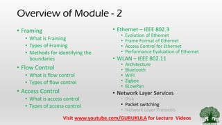
• What is Packet Switching
• Different Approaches [ Datagram Approach, Virtual
Circuit Approach]](https://image.slidesharecdn.com/2-200809145209/85/2-9-network-layer-services-packet-switching-21-320.jpg)

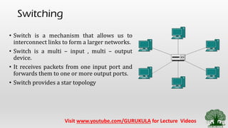
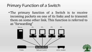
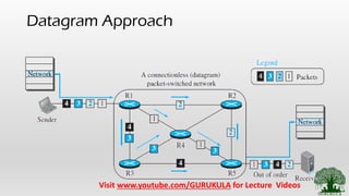
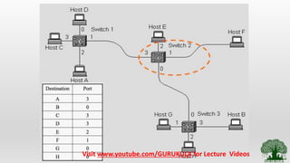
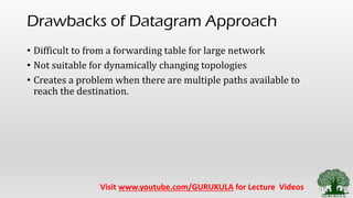
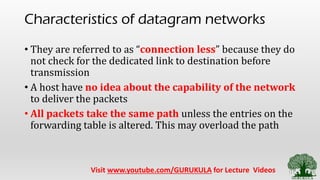
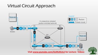
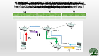
The document provides a comprehensive overview of communication networks focusing on the network layer services, packet switching techniques, and types of framing and flow control. It discusses two main approaches to packet switching: the connectionless datagram approach and the connection-oriented virtual circuit approach, detailing their processes, advantages, and drawbacks. Additionally, it covers the significance of switches in network topology and provides references for further learning.