Downloaded 717 times


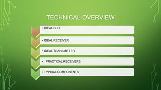
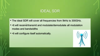
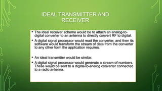


This document provides an overview of software-defined radio (SDR), including its definition, history, advantages, technical overview, and architecture. SDR is defined as a radio system where components typically implemented in hardware, such as mixers and filters, are instead implemented through software. The term was coined in 1991, with an early military project in 1992. SDR provides advantages like complete digital baseband processing and faster software prototyping. Its technical overview describes ideal SDR components and practical implementations using digital signal processing and field-programmable gate arrays.


![Getting Started with Apache Spark: Big Data Made Simple [Free Meetup]](https://cdn.slidesharecdn.com/ss_thumbnails/apachesparkgettingstarted-260203175547-8361bcc3-thumbnail.jpg?width=640&height=640&fit=bounds)


