Downloaded 85 times


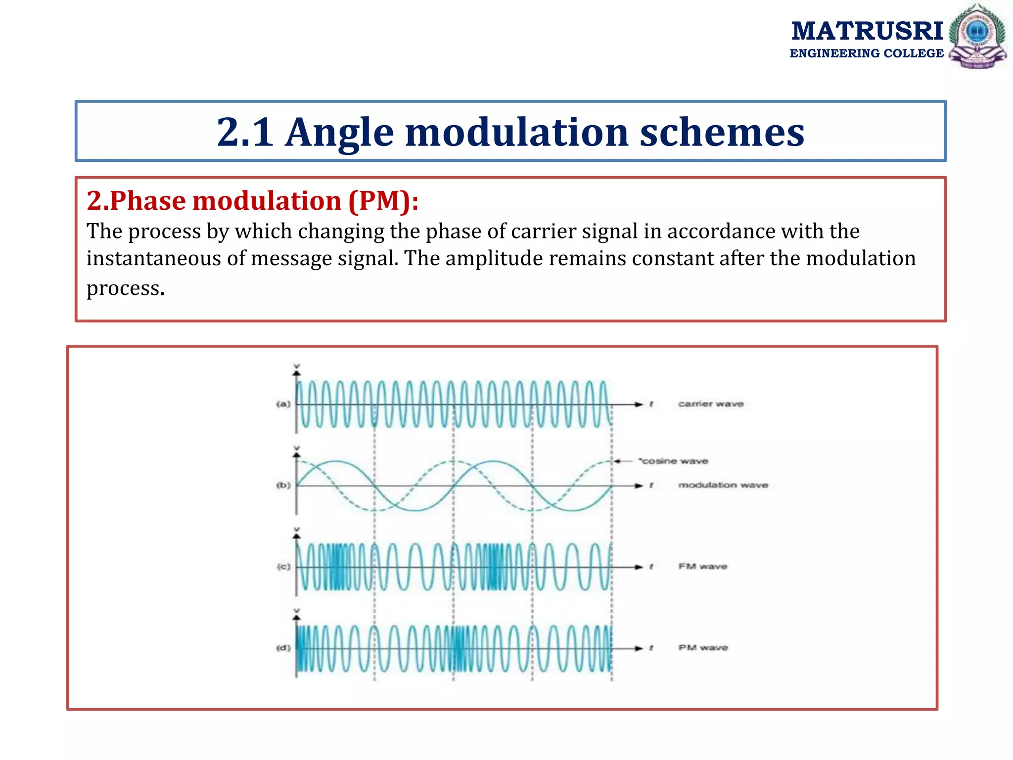


![Types of FM Modulation:
NBFM (Narrow Band FM):
2.3 Types of FM modulation
MATRUSRI
ENGINEERING COLLEGE
)
sin
cos(
)
( t
t
A
t
S m
f
C
C
FM
Depends upon the Modulation index ,Frequency modulation classified into 2 types:
1. NBFM (Narrow Band FM) if
2. WBFM (Wide Band FM)
1
f
1
f
1
f
)
2
sin
2
cos(
)
( t
f
t
f
A
t
S m
f
C
C
FM
sin
1
cos
"
"
2
sin
.
,
3
.
0
1
:
sin
)]
2
sin(
).
2
sin(
)
2
sin
cos(
).
2
[cos(
)
(
tbe
f
Let
rad
ceNBFM
t
f
t
f
t
f
t
f
A
t
S
m
f
f
m
f
C
m
f
C
C
FM
)]
2
sin(
).
2
sin(
[
)]
2
[cos(
)
(
: t
f
t
f
A
t
f
A
t
S
Then c
m
f
c
c
c
FM
](https://image.slidesharecdn.com/unit-2anglemodulation-230123162545-41234183/75/Unit-2-Angle-Modulation-ppt-20-2048.jpg)
![MATRUSRI
ENGINEERING COLLEGE
2.3 TYPES OF FM MODULATION
NBFM (Narrow Band FM):
NBPM (Narrow Band PM):
)]
)
(
2
sin
2
)
)
(
2
sin
2
)]
2
[cos(
)
(
)]
)
(
2
sin
)
)
(
2
[sin
2
)]
2
[cos(
)
(
)]
2
sin(
).
2
cos(
[
)]
2
[cos(
)
(
t
f
f
A
t
f
f
A
t
f
A
t
S
t
f
f
t
f
f
A
t
f
A
t
S
t
f
t
f
A
t
f
A
t
S
c
m
c
p
c
m
c
P
c
c
c
PM
c
m
c
m
c
P
c
c
c
PM
c
m
P
c
c
c
PM
)]
)
(
2
cos
2
)
)
(
2
cos
2
)]
2
[cos(
)
(
)]
)
(
2
cos
)
)
(
2
[cos
2
)]
2
[cos(
)
(
)]
2
sin(
).
2
sin(
[
)]
2
[cos(
)
(
t
f
f
A
t
f
f
A
t
f
A
t
S
t
f
f
t
f
f
A
t
f
A
t
S
t
f
t
f
A
t
f
A
t
S
c
m
c
f
c
m
c
f
c
c
c
FM
c
m
c
m
c
f
c
c
c
FM
c
m
f
c
c
c
FM
](https://image.slidesharecdn.com/unit-2anglemodulation-230123162545-41234183/75/Unit-2-Angle-Modulation-ppt-21-2048.jpg)
![Spectrum of NBFM:
2.3 Types of FM modulation
MATRUSRI
ENGINEERING COLLEGE
)]
)
(
2
sin
2
)
)
(
2
cos
2
)]
2
[cos(
)
( t
f
f
A
t
f
f
A
t
f
A
t
S c
m
c
f
c
m
c
f
c
c
c
FM
](https://image.slidesharecdn.com/unit-2anglemodulation-230123162545-41234183/75/Unit-2-Angle-Modulation-ppt-22-2048.jpg)
![WBFM (WIDE BAND FM):
2.3 Types of FM modulation
MATRUSRI
ENGINEERING COLLEGE
1
f
)
2
sin
2
cos(
)
( t
f
t
f
A
t
S m
f
C
C
FM
]
)
(
2
cos[
)
(
.
)
(
]
).
(
Re[
.
)
(
]
).
(
.
Re[
.
)
(
)
2
2
(
2
2 0
n m
c
f
n
c
WBFM
n
t
nf
f
j
f
n
c
n
t
n
j
f
n
t
f
j
c
t
nf
f
J
A
t
S
e
J
A
t
S
e
J
e
A
t
S
m
c
c
](https://image.slidesharecdn.com/unit-2anglemodulation-230123162545-41234183/75/Unit-2-Angle-Modulation-ppt-23-2048.jpg)

![2.4 FM spectrum in terms of Bessel functions
WBFM (WIDE Band FM):Bessel Function
MATRUSRI
ENGINEERING COLLEGE
]
)
2
cos(
cos
).
(
)
2
cos(
).
(
[
]
)
cos(
cos
).
(
)
cos(
).
(
[
cos
)
(
)
(
)
(
2
cos
).
(
)
(
2
2
1
1
0
t
J
t
J
A
t
J
t
J
A
t
J
A
t
S
t
nf
f
J
A
t
S
m
c
m
c
c
m
c
m
c
c
c
c
WBFM
m
n
c
n
c
FM
]
)
2
cos(
cos
)
2
).[cos(
(
]
)
cos(
)
).[cos(
(
cos
)
(
)
(
2
1
0
t
t
J
A
t
t
J
A
t
J
A
t
S
m
c
m
c
c
m
c
m
c
c
c
c
WBFM
](https://image.slidesharecdn.com/unit-2anglemodulation-230123162545-41234183/75/Unit-2-Angle-Modulation-ppt-25-2048.jpg)
![WBFM with Bessel Function:
Properties of BESSELS Functions:
2.4 FM spectrum in terms of Bessel functions
MATRUSRI
ENGINEERING COLLEGE
)
(
2
)
(
)
(
.
5
0
)
(
"
"
arg
.
4
0
)
(
,
2
/
)
(
,
1
)
(
;
!
2
/
)
(
)
1
(
.
3
1
)
(
.
2
)
(
)
1
(
)
(
.
1
1
1
1
0
2
n
n
n
n
o
n
n
n
n
n
n
n
n
J
n
J
J
J
Lt
n
evaluesof
Forl
J
J
J
n
J
lueof
Forsmallva
J
J
J
]
)
2
cos(
cos
)
2
).[cos(
(
]
)
cos(
)
).[cos(
(
cos
)
(
)
(
2
1
0
t
t
J
A
t
t
J
A
t
J
A
t
S
m
c
m
c
c
m
c
m
c
c
c
c
WBFM
](https://image.slidesharecdn.com/unit-2anglemodulation-230123162545-41234183/75/Unit-2-Angle-Modulation-ppt-26-2048.jpg)


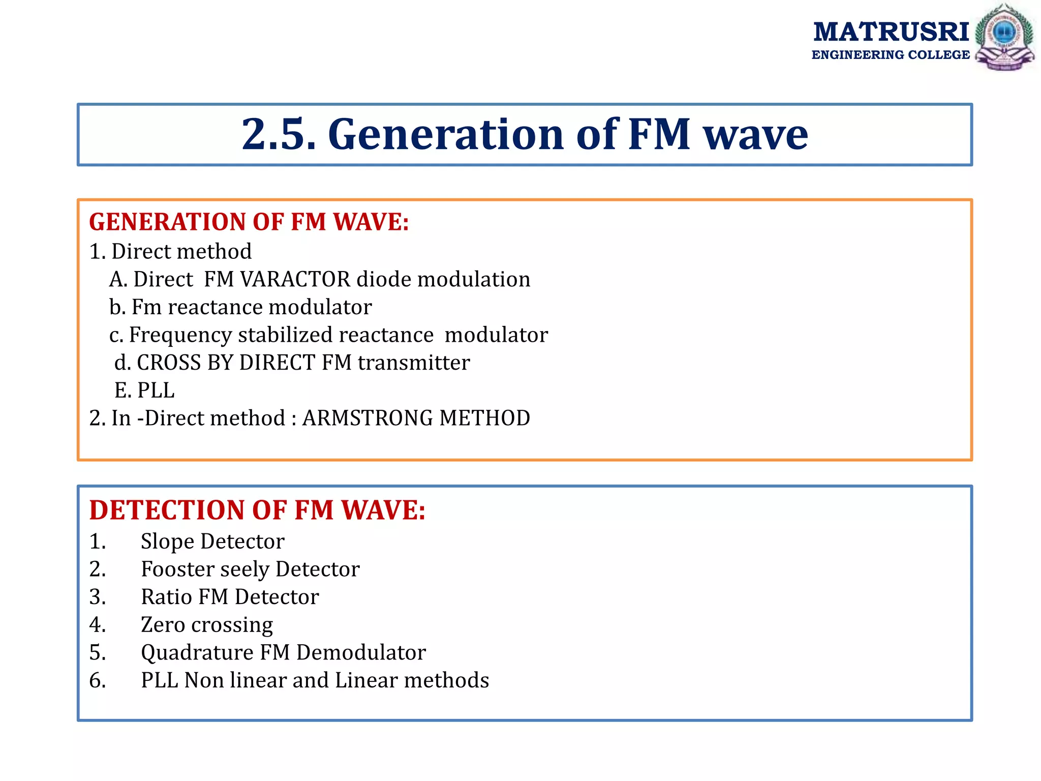
![GENERATION OF FM WAVE: Direct method:
2.5. Generation of FM wave
MATRUSRI
ENGINEERING COLLEGE
)
(
)
(
2
)
(
2
1
)]
(
1
(
)
(
)]
(
1
[
)
(
)
(
1
[
2
1
)
(
)
(
(
2
1
)
(
,
,
0
)
(
,
2
1
0
0
0
0
0
0
2
1
0
0
2
1
0
0
0
0
0
0
0
0
0
0
t
m
kf
f
t
m
c
kf
f
t
m
c
k
t
m
c
k
f
t
f
t
m
c
k
f
t
f
t
m
c
k
C
L
t
f
t
km
C
L
t
f
thenfreq
t
m
when
C
L
f
i
i
i
i
](https://image.slidesharecdn.com/unit-2anglemodulation-230123162545-41234183/75/Unit-2-Angle-Modulation-ppt-31-2048.jpg)
![GENERATION OF FM WAVE: IN-DIRECT METHOD:
2.5. Generation of FM wave
MATRUSRI
ENGINEERING COLLEGE
First Generate NBFM then convert into WBFM
]
sin
cos[
)
(
.....
]
sin
cos[
[
]
sin
cos[
.
)
(
.....
)
(
]
sin
cos[
)
(
0
2
1
0
2
2
2
2
2
1
1
1
0
2
1
t
n
t
n
A
t
V
AfterBPF
t
t
A
a
t
t
A
a
t
V
V
a
V
a
V
a
t
V
t
t
A
t
V
m
c
m
c
c
m
c
c
m
c
c
](https://image.slidesharecdn.com/unit-2anglemodulation-230123162545-41234183/75/Unit-2-Angle-Modulation-ppt-32-2048.jpg)


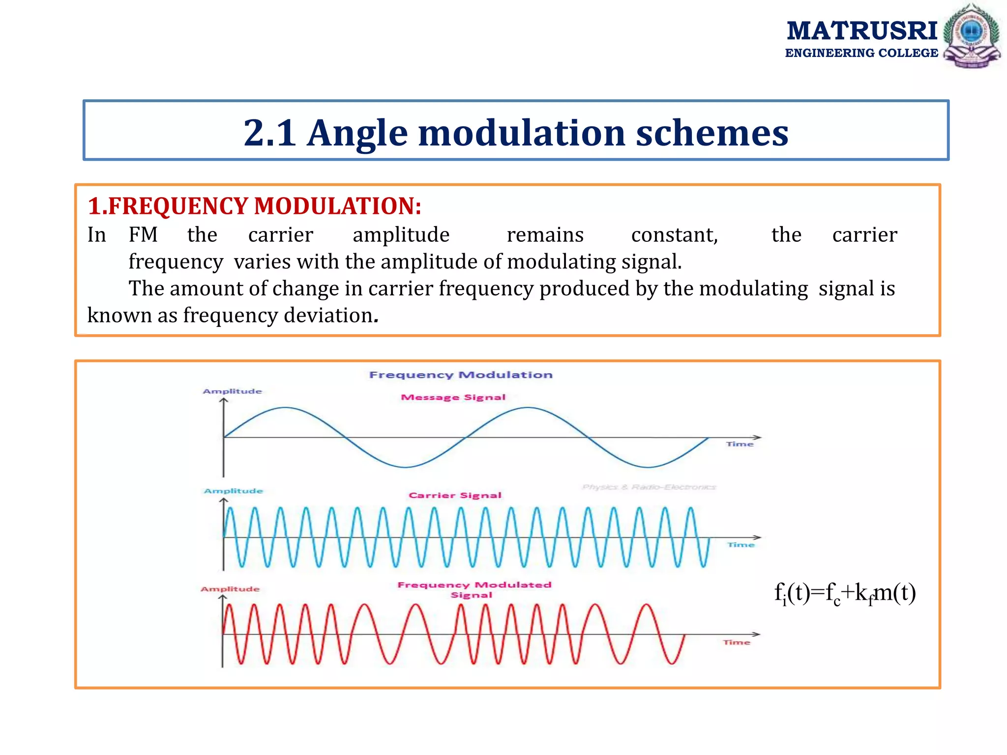
![A phase-locked loop or phase lock loop (PLL) is a control system that generates an
output signal whose phase is related to the phase of an input signal. There are several
different types; the simplest is an electronic circuit consisting of a variable frequency
oscillator and a phase detector in a feed back loop the oscillator generates a periodic
signal, and the phase detector compares the phase of that signal with the phase of the
input periodic signal, adjusting the oscillator to keep the phases matched.
Phased Lock Loop (PLL)
MATRUSRI
ENGINEERING COLLEGE
Sout ( t )
Sf ( t )
Sphase( t )
Voltage Controlled
Oscillator (VCO)
SVCO ( t ) = AVCO ·sin [ 0 t + 0( t )]
Sf ( t ) = Af ·cos [ c t + ( t )]
SVCO ( t )
Phase
Detector
Low-pass
filter](https://image.slidesharecdn.com/unit-2anglemodulation-230123162545-41234183/75/Unit-2-Angle-Modulation-ppt-46-2048.jpg)


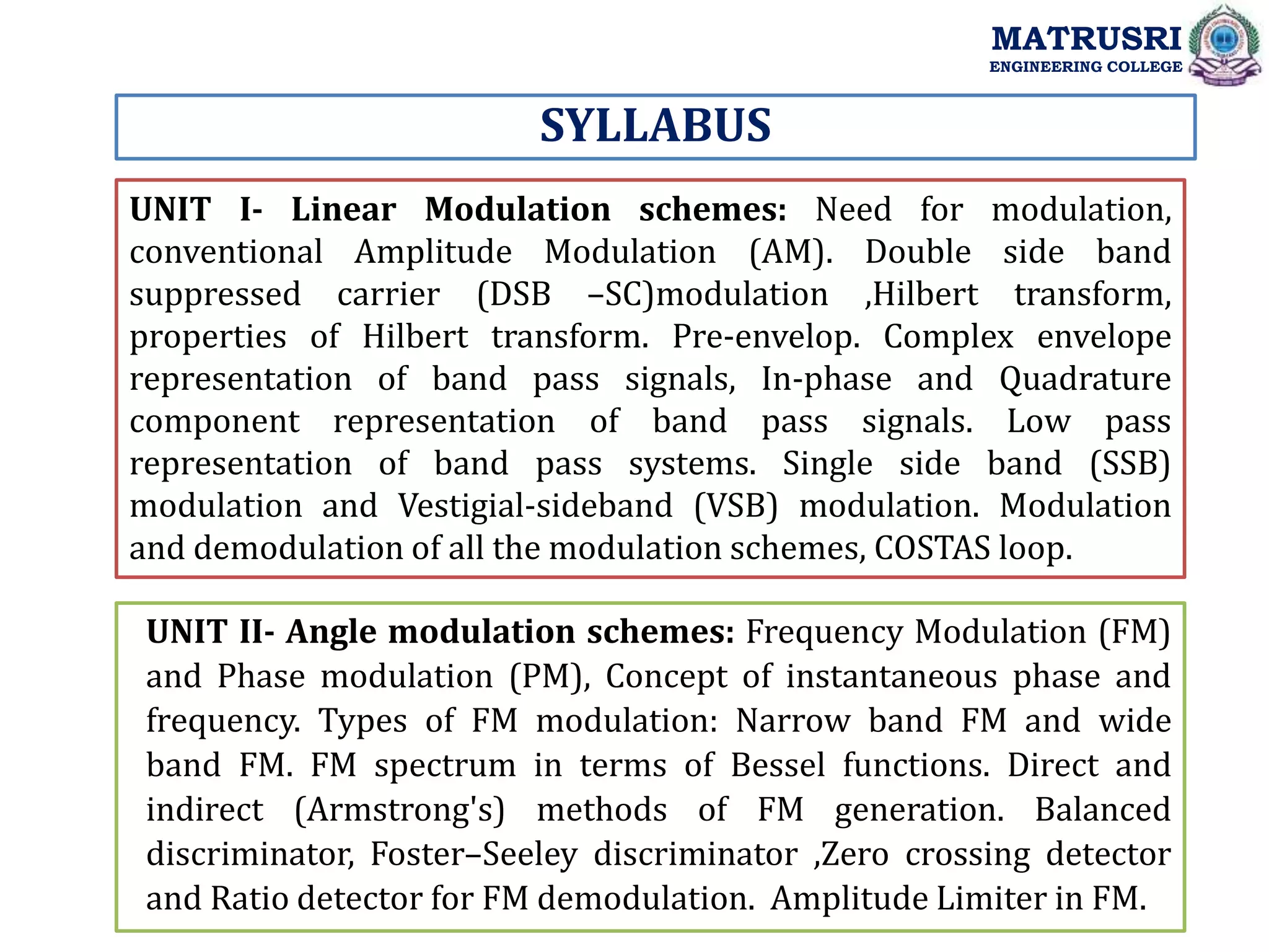
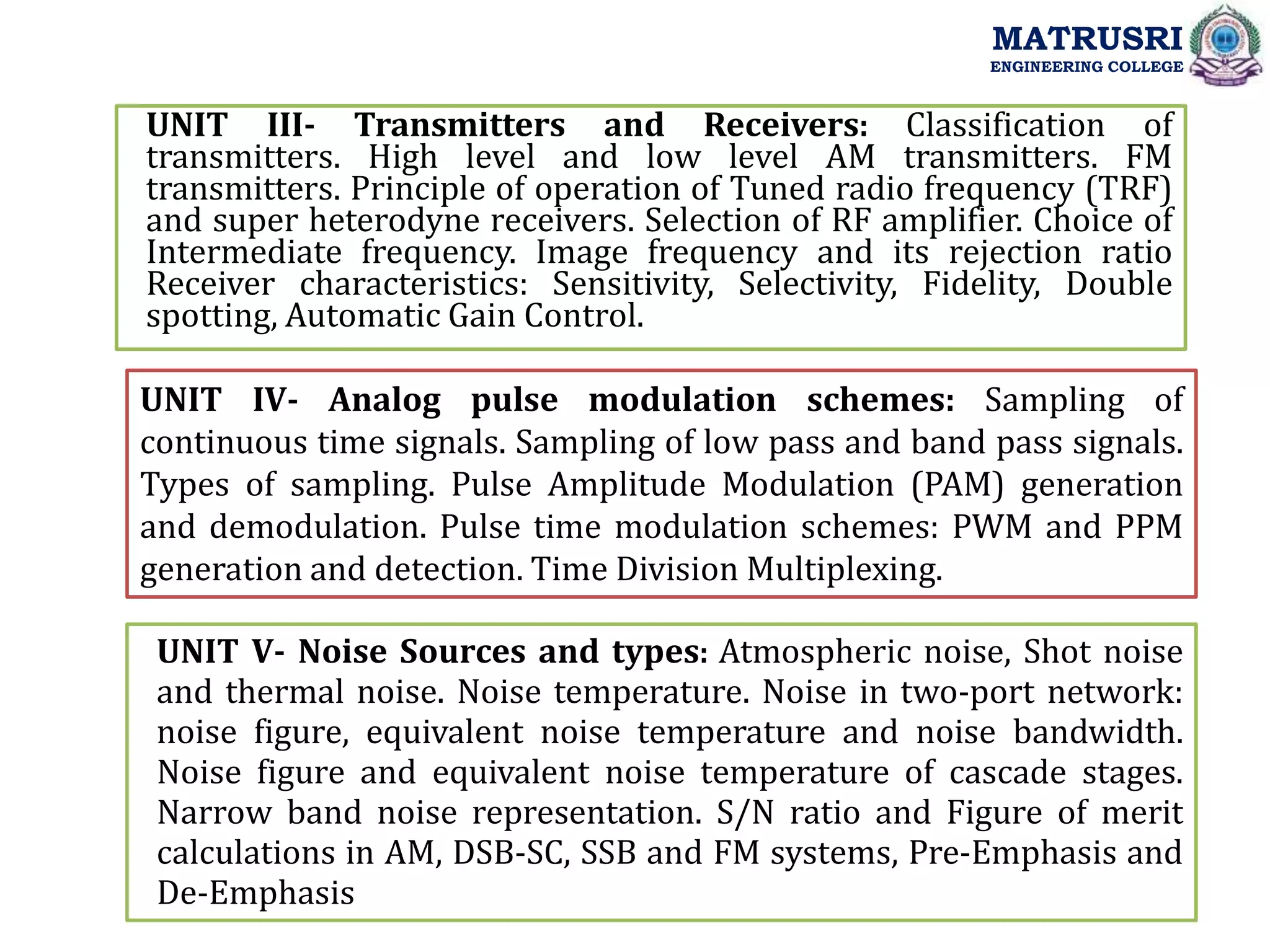
This document provides information about the Analog Communications course offered at Matrusri Engineering College. It includes the course objectives, outcomes, syllabus, lesson plan and introduction. The key points are: - The course objectives are to analyze analog communication systems and understand various analog modulation techniques, noise performance and AM/FM receivers. - The syllabus covers topics like linear modulation schemes, angle modulation schemes, transmitters and receivers, noise sources and types, and analog pulse modulation schemes. - The lesson plan provides details of topics to be covered in each unit, including frequency modulation, phase modulation, and modulation/demodulation techniques. - The introductions provide an overview of the topics to be discussed in each