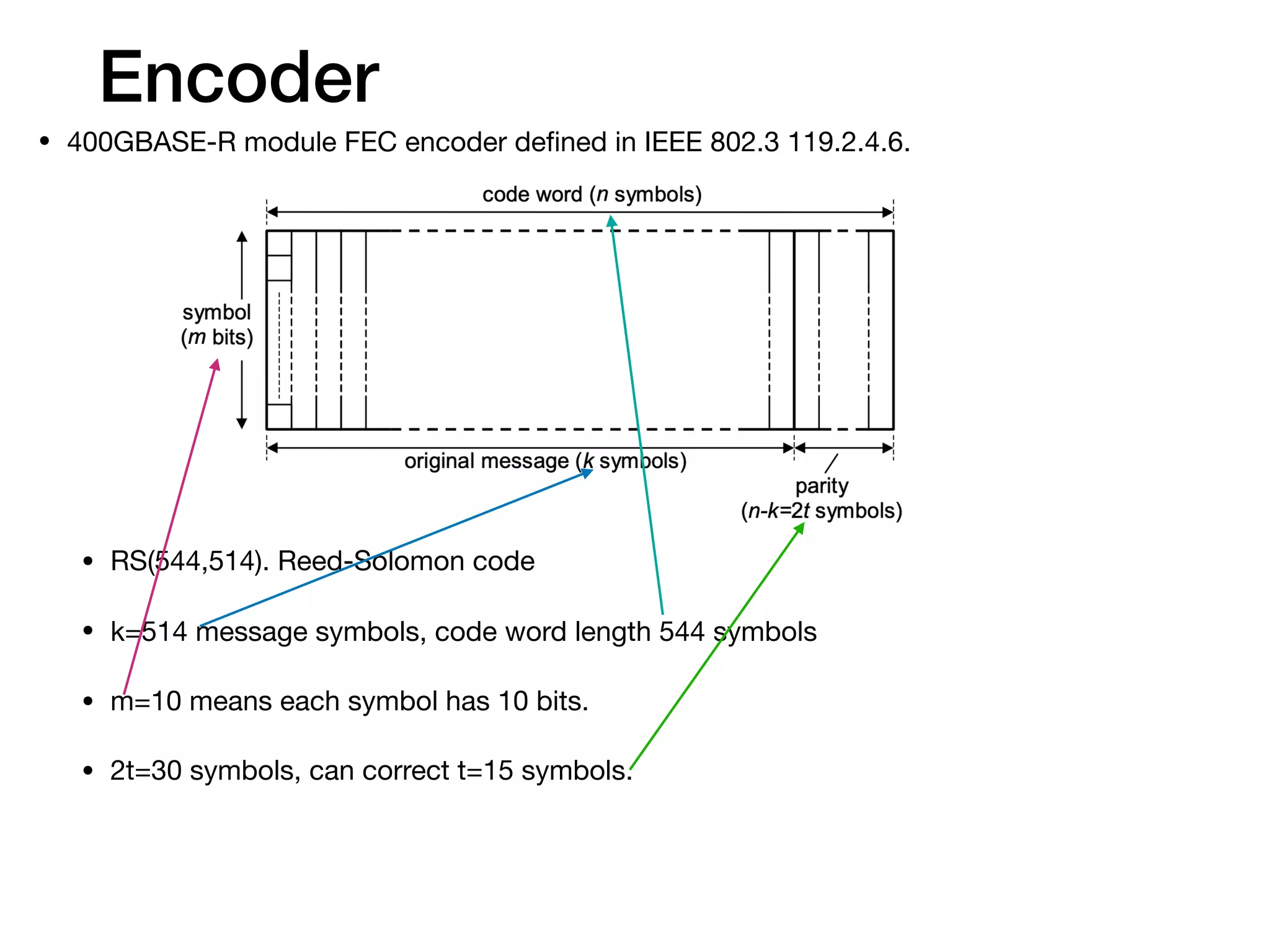
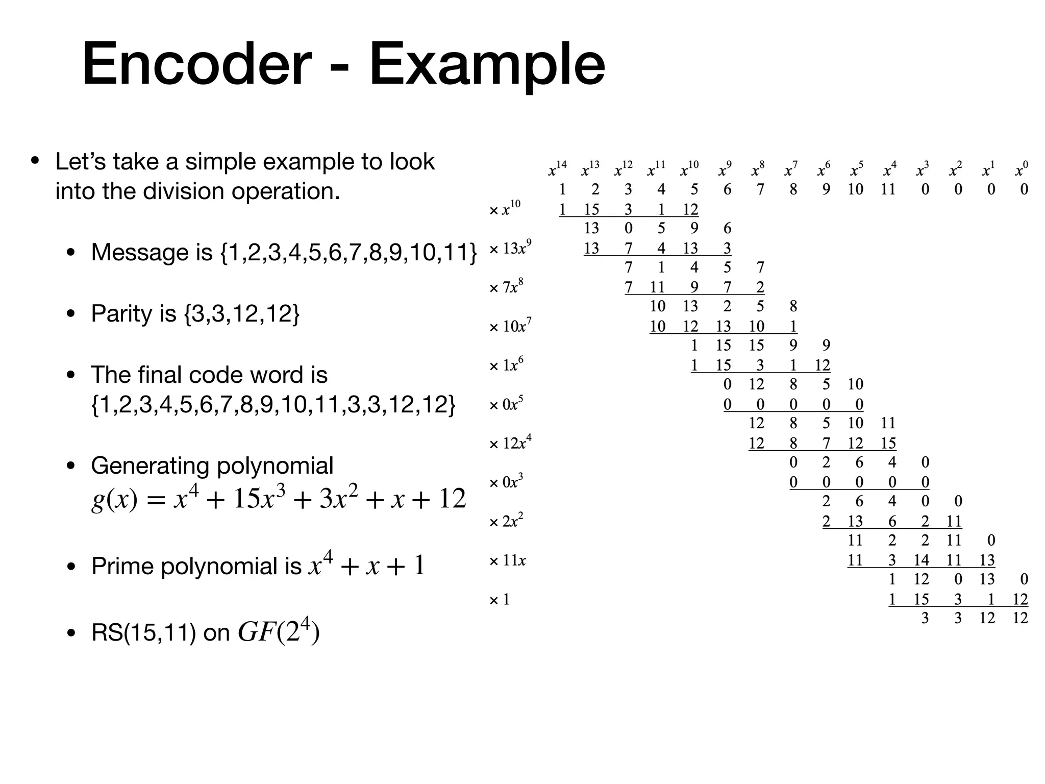
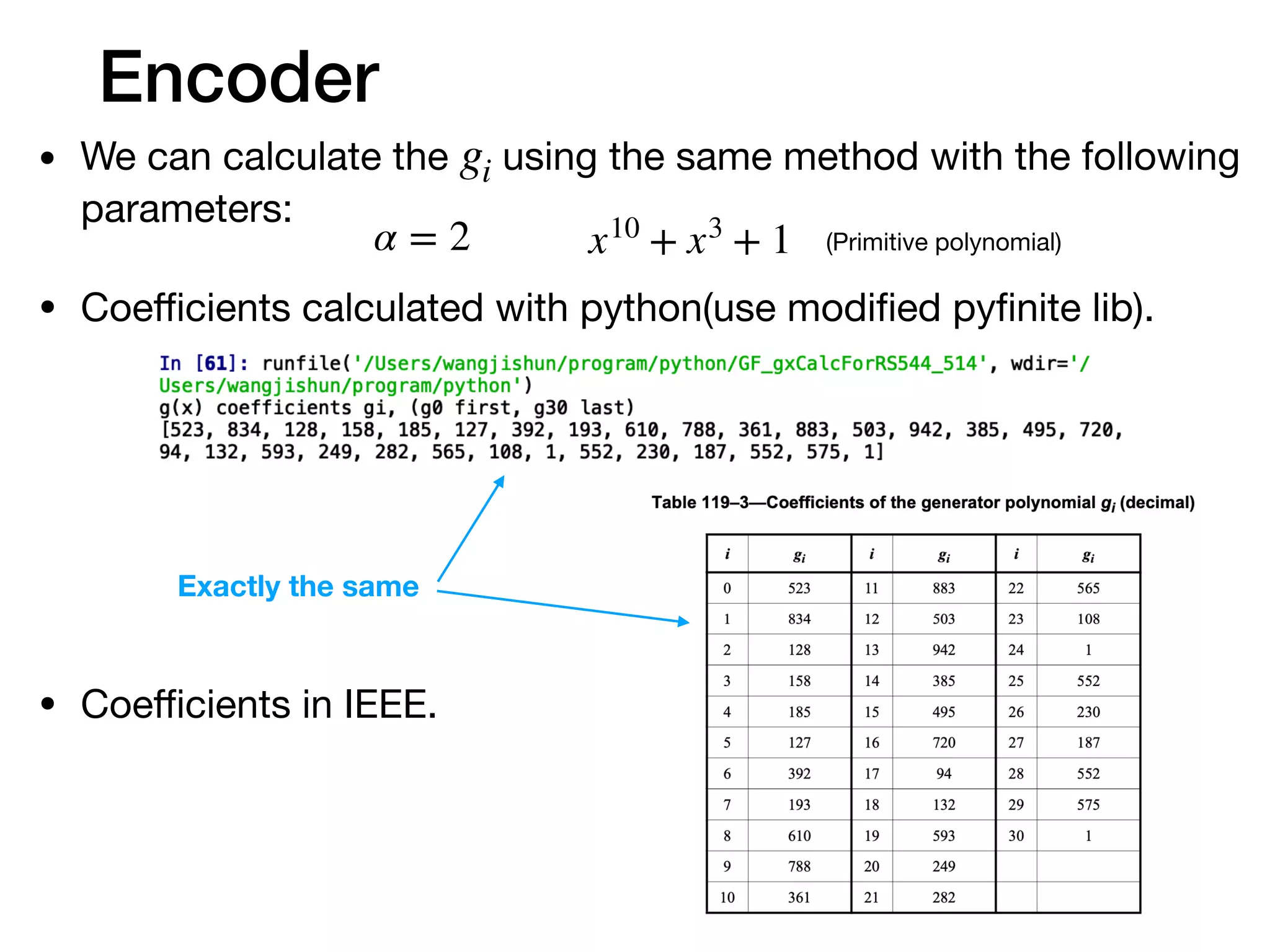
The document provides an in-depth explanation of Reed-Solomon coding, specifically the RS(544,514) code used in 200/400GBASE-R forward error correction. It details the mathematical foundations of finite fields and polynomial operations that underpin the encoding and decoding processes, including error correction strategies using syndromes, error locator polynomials, and error evaluation steps. Examples illustrate how to compute codewords from messages and reconstruct messages from corrupted codewords using the defined algorithms.


![Encoder
• After we figure out all the detail of the calculation, let’s hold on a moment
to see what’s the mathematical idea behind the calculation.
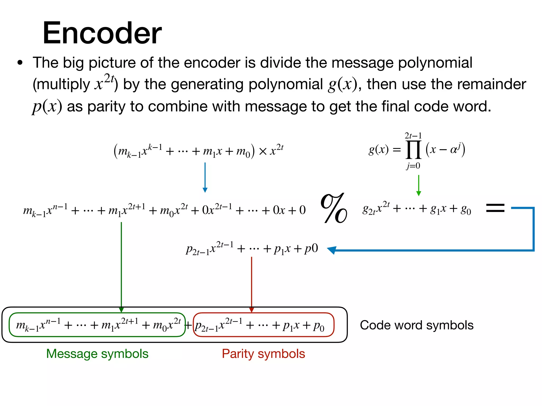
• The final codeword is combined with message and parity symbols. And
the parity comes from the remainder. So the codeword can be divided by
. That means are roots of the codeword polynomial.g(x) αj
% = 0
2t−1
∏
j=0
(x − αj
)mk−1xn−1
+ ⋯ + m1x2t+1
+ m0x2t
+ p2t−1x2t−1
+ ⋯ + p1x + p0
Message symbols Parity symbols
C(x) = cn−1xn−1
+ ⋯ + c1x + c0
C(αj
) = CHT
= [c0 c1 ⋯ cn−1]
1 1 1 ⋯ 1
1 α1
α2
⋯ α2t−1
1 α2
α4
⋯ α(2t−1)2
⋯ ⋯ ⋯ ⋯ ⋯
1 αn−1
α2(n−1)
⋯ α(2t−1)(n−1)
= O1×2t
• Rewrite the equation in matrix](https://image.slidesharecdn.com/understandfecv03-200123163933/75/Understanding-Reed-Solomon-code-14-2048.jpg)
![Encoder
• This equation means the codeword subspace is perpendicular
to the ’s row space.HT
[c0 c1 ⋯ cn−1]
1 1 1 ⋯ 1
1 α1
α2
⋯ α2t−1
1 α2
α4
⋯ α(2t−1)2
⋯ ⋯ ⋯ ⋯ ⋯
1 αn−1
α2(n−1)
⋯ α(2t−1)(n−1)
= O1×2t
• The encoder mapping the -dimensional original message into
-dimensional space. The -dimensional codeword subspace is
perpendicular to -dimensional subspace.
• If the transmission introduce any error make to , then
they’re not perpendicular any more. Then we know there are
errors, and maybe we can correct the errors.
k mk
n k
2t (2t = n − k)
C(x) R(x)](https://image.slidesharecdn.com/understandfecv03-200123163933/75/Understanding-Reed-Solomon-code-15-2048.jpg)
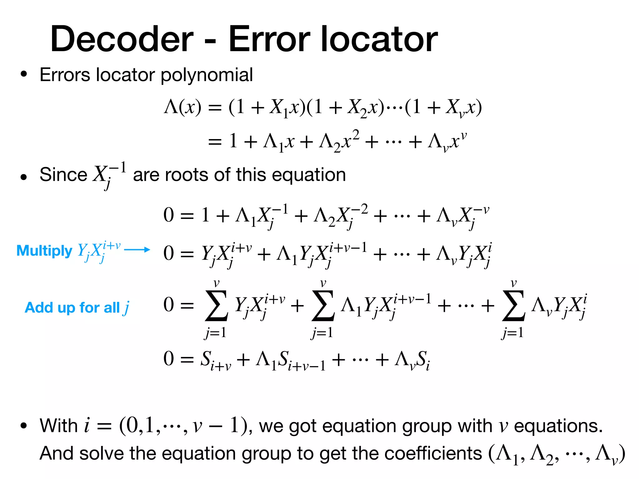
![Decoder
• The result of is no longer Zero-matrix if there are errors.
• The result will be S. (short for Syndromes)
RHT
[r0 r1 ⋯ rn−1]
1 1 1 ⋯ 1
1 α1
α2
⋯ α2t−1
1 α2
α4
⋯ α(2t−1)2
⋯ ⋯ ⋯ ⋯ ⋯
1 αn−1
α2(n−1)
⋯ α(2t−1)(n−1)
= S
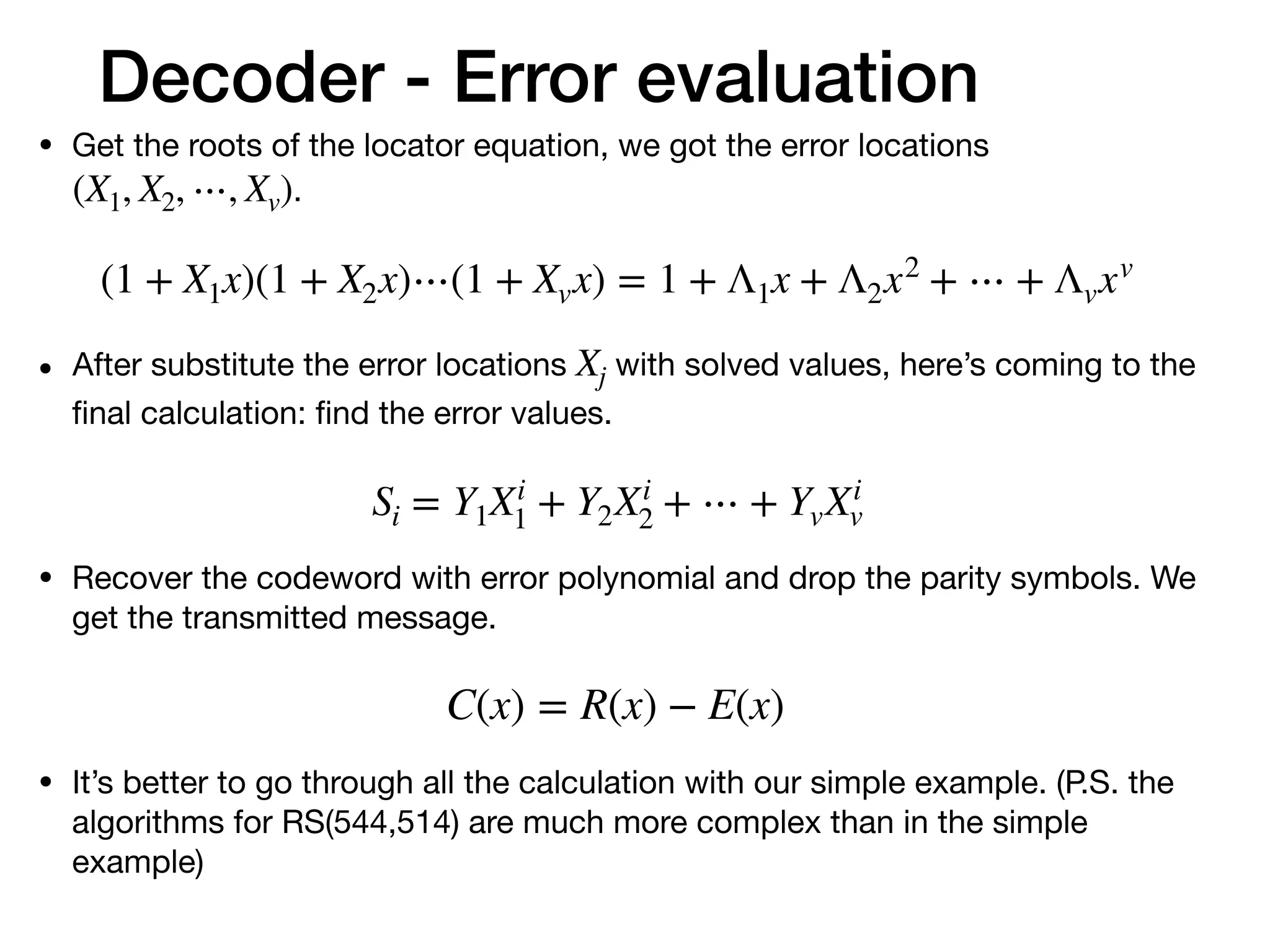
• We can correct the message if we know the error locations and
error values.](https://image.slidesharecdn.com/understandfecv03-200123163933/75/Understanding-Reed-Solomon-code-16-2048.jpg)

![Decoder - Example
• First, use received symbols to get the ‘Syndromes’.
[12 12 7 3 11 10 9 8 7 0 5 4 3 2 1]
1 1 1 1
1 2 4 8
1 4 3 12
1 8 12 10
1 3 5 15
1 6 7 1
1 12 15 8
1 11 9 12
1 5 2 10
1 10 8 15
1 7 6 1
1 14 11 8
1 15 10 12
1 13 14 10
1 9 13 15
= [2 10 9 1]
errors
Syndromesreceived codeword
parity check matrix
Here we use the parity check matrix. Divide the codeword
with with do the same thing.g(x)](https://image.slidesharecdn.com/understandfecv03-200123163933/75/Understanding-Reed-Solomon-code-20-2048.jpg)
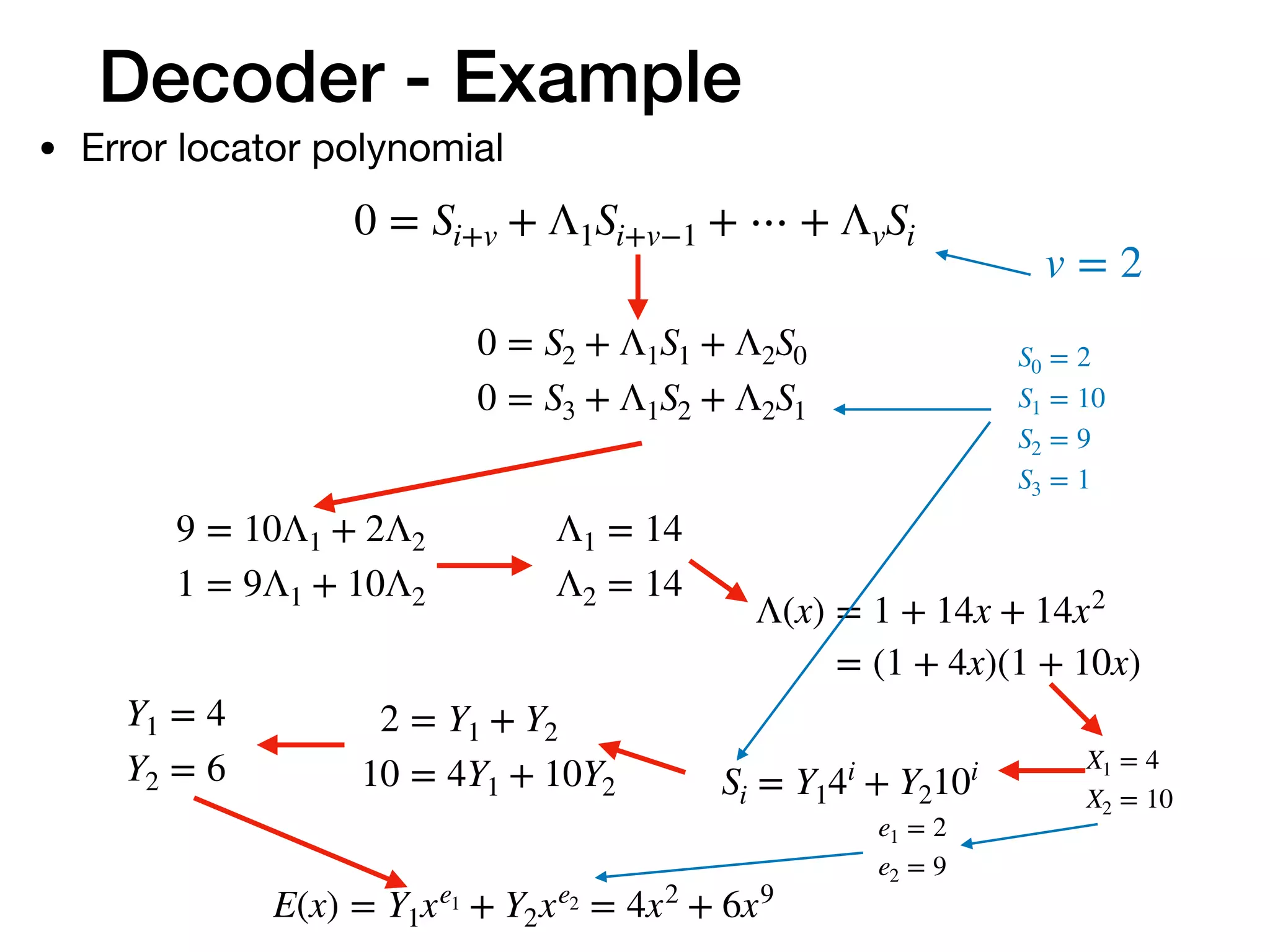
![Decoder - Example
• Decode finish
E(x) = 6x9
+ 4x2
R(x) = 1x14
+ 2x13
+ 3x12
+ 4x11
+ 5x10
+ 0x9
+ 7x8
+ 8x7
+ 9x6
+ 10x5
+ 11x4
+ 3x3
+ 7x2
+ 12x + 12
C(x) = 1x14
+ 2x13
+ 3x12
+ 4x11
+ 5x10
+ 6x9
+ 7x8
+ 8x7
+ 9x6
+ 10x5
+ 11x4
+ 3x3
+ 3x2
+ 12x + 12
[1 2 3 4 5 6 7 8 9 10 11]](https://image.slidesharecdn.com/understandfecv03-200123163933/75/Understanding-Reed-Solomon-code-22-2048.jpg)