Download to read offline
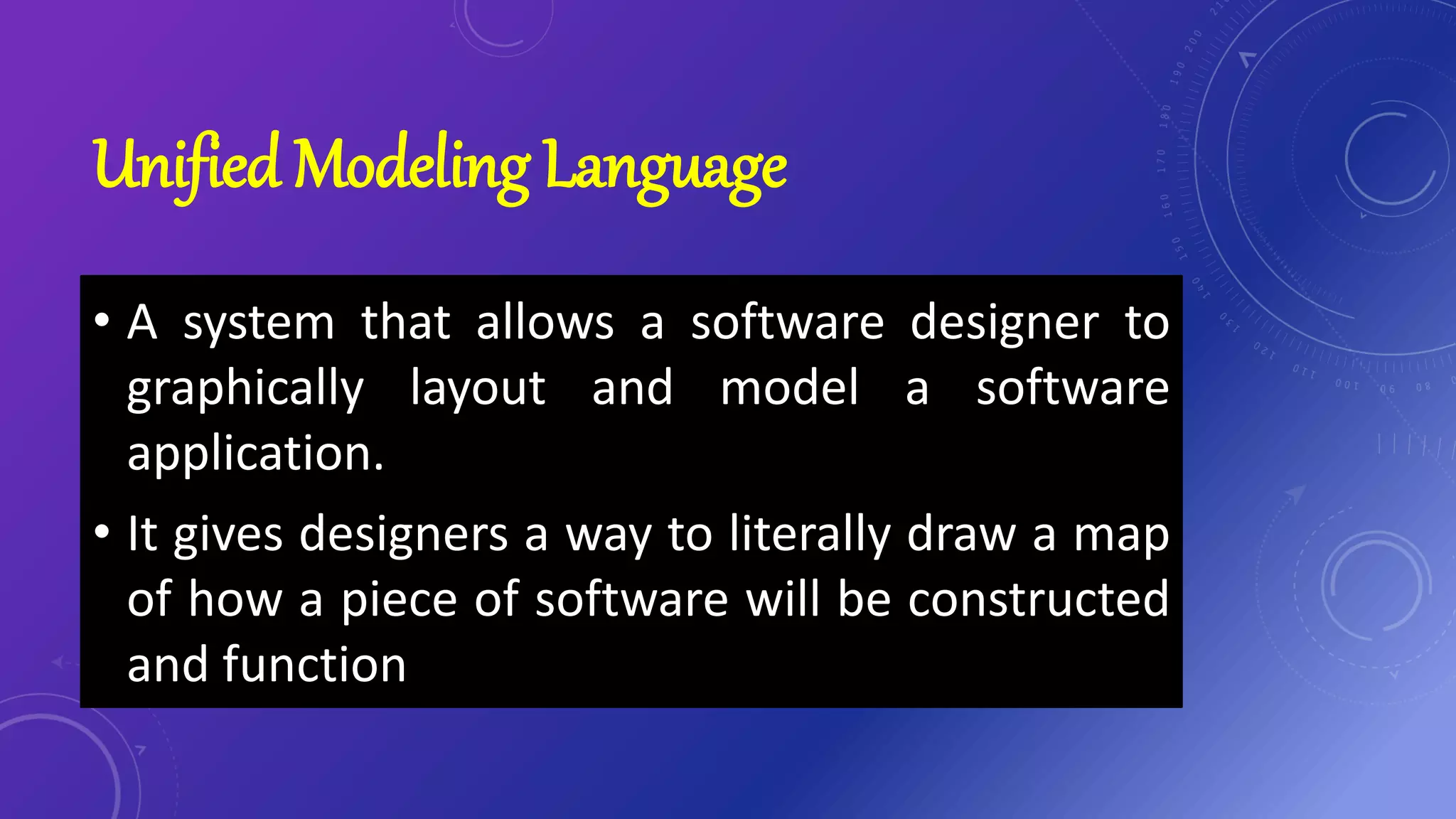


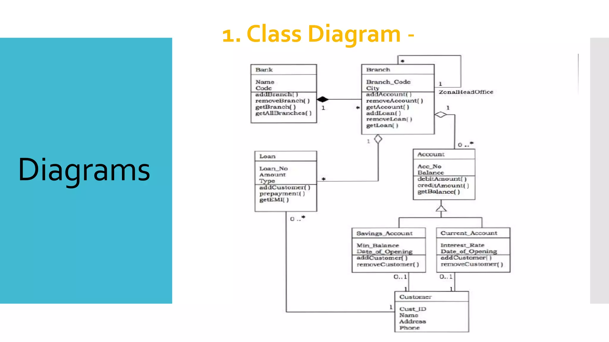


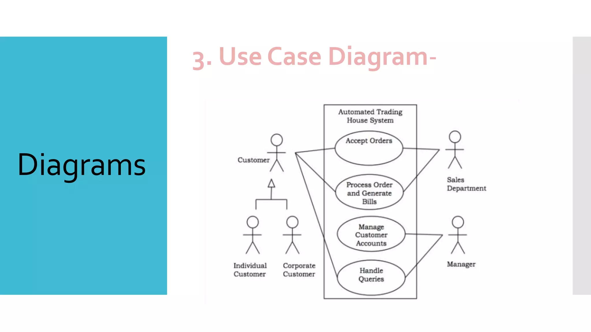


UML is a system that allows software designers to graphically model applications using diagrams, classes, relationships and other elements. It has basic building blocks like things, relationships and diagrams. The main diagram types are class, object, use case, sequence, state machine, activity, component and deployment diagrams which are used to model different aspects of a software system.