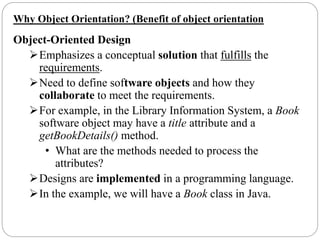
An employee who helps passengers
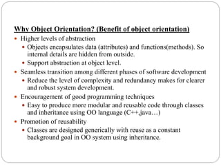
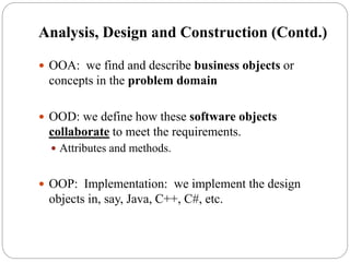
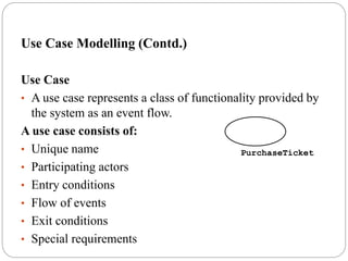
- A use case has a unique name and an optional description.
- Examples:
- Buy ticket: Purchase a ticket for travel
- Check schedule: Check train schedule and availability
- Provide location: Provide train location to passengers
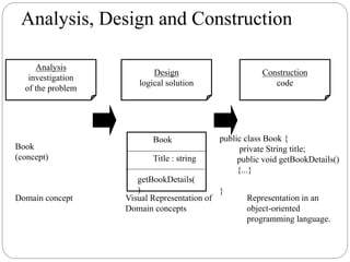
Buy ticket
Check schedule
Provide location
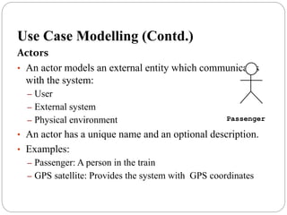
Passenger
Assistant
GPS satellite
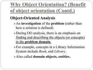
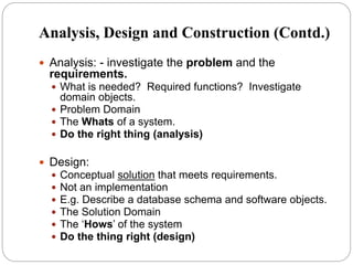
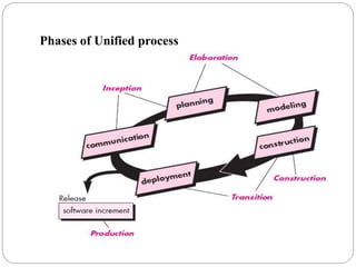
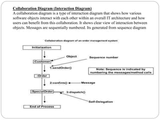
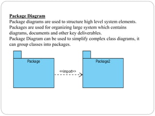
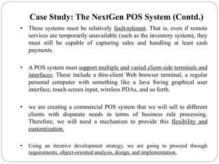
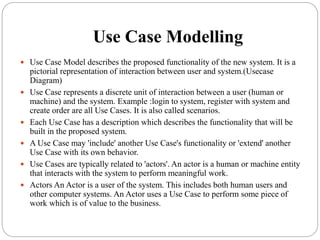
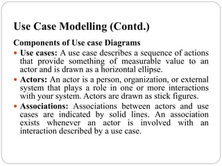
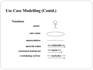
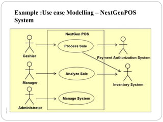
Use Case Modelling (Contd.)
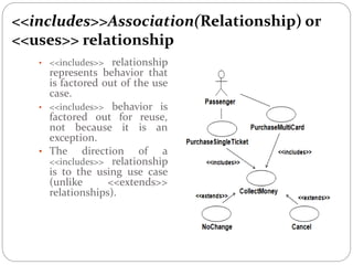
Associations
- Associations connect actors to the use cases they are involved in.
- Types of associations:
1. Basic association: Actor uses the use case
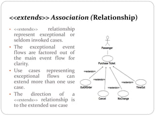
2. Extend association: Extends the basic behavior of a use case
3