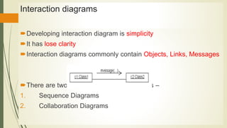
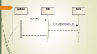
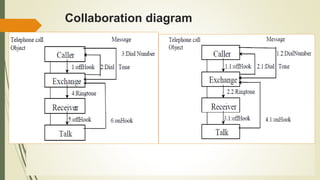
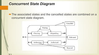
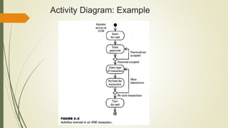
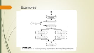
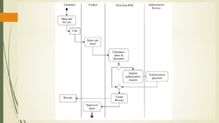
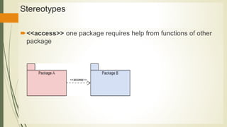
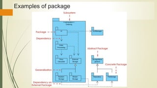
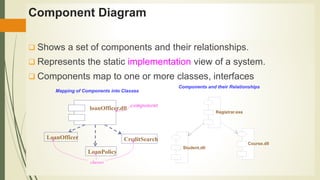
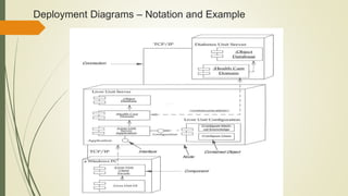
This document discusses various UML diagrams used for dynamic modeling and implementation, including their notation and usage. It describes sequence diagrams, collaboration diagrams, state machine diagrams, activity diagrams, package diagrams, component diagrams, and deployment diagrams. Sequence and collaboration diagrams are used to model system interactions. State machine diagrams capture system behavior, while activity diagrams depict workflow. Package, component, and deployment diagrams aid in structuring system implementation across different modules.
The document provides an overview of the Unified Modeling Language (UML), including its history, purpose, key diagrams, and changes between versions. It describes how UML was created in the 1990s to standardize modeling of software systems, and discusses the main structural and behavioral diagrams used to model different aspects of a system, such as class, use case, activity, and state diagrams. The document also summarizes new elements introduced in UML 2.0, such as changes to activity diagrams.
The document provides an overview of Unified Modeling Language (UML). It discusses that UML is a standard modeling language used to visualize, specify and document artifacts of a software system. It then summarizes the history and evolution of UML from its origins combining different modeling approaches in the 1980s-1990s to the current version. The document also lists and briefly describes the main UML diagram types including class, use case, activity, sequence, collaboration, state chart, component and deployment diagrams. For each diagram type, it highlights the key elements and purpose.
The document discusses the Unified Modeling Language (UML) which is a general-purpose modeling language used to visualize, specify, construct, and document software systems. UML uses graphical notation to represent the design of software projects including concepts like use case diagrams, class diagrams, sequence diagrams, and more. It provides a standard way to visualize a system from different perspectives including structural and behavioral views.
The document provides an introduction to the Unified Modeling Language (UML). It discusses the key principles of modeling and an overview of UML. The UML is a standard language for writing software blueprints and can be used to visualize, specify, construct, and document software systems. The UML has building blocks like classes, objects, use cases and relationships. It consists of diagrams like class diagrams, sequence diagrams, and state machine diagrams. The UML addresses multiple views of a system including use case, design, interaction and implementation views.
The document discusses various Unified Modeling Language (UML) diagrams used to model different aspects of software systems. It describes structure diagrams like class diagrams that show system composition and deployment diagrams that map software to hardware. It also covers behavioral diagrams like use case diagrams, interaction diagrams (sequence and communication diagrams), state-chart diagrams, and activity diagrams that model dynamic system behavior through object interactions and state transitions. Specific examples are provided for how to construct and interpret sequence diagrams, state machine diagrams, and activity diagrams.
UML (Unified Modeling Language) is a standard language for specifying, visualizing, and documenting models of software systems. The document discusses the history and evolution of UML, provides definitions and examples of various UML diagram types including class, object, use case, state, activity, sequence, and others. It also explains how UML diagrams can be used to model different views of a system, such as structural relationships and dynamic behavior over time.
UML is a modeling language used to visualize, specify, construct, and document software systems. It provides standard graphical notations for modeling structural and behavioral aspects of a system using diagrams. The key UML diagram types are structural diagrams (e.g. class, component), behavioral diagrams (e.g. use case, activity), and interaction diagrams (e.g. sequence, communication). UML was created through the unification of several popular modeling languages in the 1990s and is now managed by the Object Management Group.
This document provides an overview of various Unified Modeling Language (UML) diagrams, including use case diagrams, class diagrams, activity diagrams, sequence diagrams, and state machine diagrams. It describes the basic components and purposes of each diagram type.
The document discusses various UML diagrams used for modeling dynamic and implementation aspects of software systems. It describes interaction diagrams like sequence diagrams and collaboration diagrams which are used to model object interactions. It also covers state machine diagrams and activity diagrams which are used to model dynamic system behavior. Finally, it discusses implementation diagrams like package diagrams, component diagrams, and deployment diagrams which are used to model system organization and deployment.
UML stands for Unified Modelling Language.
UML is a standard language for specifying, visualizing, constructing, and documenting a system in which software represents the most significant part.
UML is different from the other common programming languages like C++, Java, COBOL etc.
UML is a pictorial language used to make software blue prints.
UML can serve as a central notation for software development process. Using UML helps project teams communicate, explore potential designs, and validate the architectural designs of software.
UML diagrams are made using notation of things and relationships.
The building blocks of UML can be defined as:
Things
Relationships
Diagrams
Things: Things are the most important building blocks of UML. Things can be:
Structural
Behavioral
Grouping
Annotational
The Structural things define the static part of the model. They represent physical and conceptual elements. Following are the brief descriptions of the structural things.
Class: Class represents set of objects having similar responsibilities.
Interface: Interface defines a set of operations which specify the responsibility of a class.
Collaboration: Collaboration defines interaction between elements.
Use case: Use case represents a set of actions performed by a system for a specific goal.
Component: Component describes physical part of a system.
Node: A node can be defined as a physical element that exists at run time.
A behavioral thing consists of the dynamic parts of UML models. Following are the behavioral things:
Interaction: Interaction is defined as a behavior that consists of a group of messages exchanged among elements to accomplish a specific task.
State machine: State machine is useful when the state of an object in its life cycle is important. It defines the sequence of states an object goes through in response to events. Events are external factors responsible for state change.
UML (Unified Modeling Language) is a standardized modeling language used to specify, visualize, construct and document the artifacts of a software system. UML uses different diagram types to model different aspects of a system, such as its static structure using class or object diagrams, or its dynamic behavior using sequence or activity diagrams. Some diagram types depict the static structure of a system, others the dynamic behavior, and some the implementation of components.
1. UML is a standardized modeling language used to visualize, specify, construct, and document a system.
2. UML includes structural elements like classes, interfaces, components as well as behavioral elements like use cases, interactions, state machines.
3. UML diagrams like class, sequence, activity diagrams are used to represent different views of a system based on its design, implementation, processes, and deployment.
The document provides information on Unified Modeling Language (UML) and its various diagrams used for modeling software systems. It discusses the background and benefits of object-oriented modeling. It then describes UML as a modeling language comprising various diagram types to capture different views of a system, including structural, behavioral, implementation and user views. Specific diagram types covered include use case diagrams, class diagrams, sequence diagrams, and object diagrams. Examples are provided for each diagram type to illustrate their elements and notation.
UML (Unified Modeling Language) is a standard language for modeling software systems using mainly graphical diagrams. It includes diagrams for use cases, class structure, object interaction, state machines, activities, components and deployment. UML aims to provide a standard way to visualize a system's architectural design which can be understood by all stakeholders and serves as input for the implementation.
The document discusses various types of Unified Modeling Language (UML) diagrams used for software modeling including state machine diagrams, deployment diagrams, package diagrams, component diagrams, and timing diagrams. It provides descriptions of each diagram type including their purpose and how they are used to model different aspects of software design.
UML is a system that allows software designers to graphically model applications using diagrams, classes, relationships and other elements. It has basic building blocks like things, relationships and diagrams. The main diagram types are class, object, use case, sequence, state machine, activity, component and deployment diagrams which are used to model different aspects of a software system.
This document outlines the components required for a case tools laboratory project. The project must include 9 components: developing a problem statement, use cases, a domain model with class diagram, sequence diagrams, state charts and activity diagrams, an architecture diagram, and testing each layer of the system. It also provides 15 suggested domains for mini-projects and lists recommended modeling tools.
An activity diagram visually presents a series of actions or flow of control in a system similar to a flowchart or a data flow diagram. They can also describe the steps in a use case diagram.
The document discusses advanced structural modeling concepts in object-oriented software engineering, including advanced classes, relationships, interfaces, types and roles, packages, and object diagrams. It defines these concepts and provides examples to illustrate their usage and relationships.
UML (Unified Modeling Language) is a standardized modeling language used to visualize, specify, construct, and document software system artifacts, enabling a systematic approach to analysis, design, and implementation. This document discusses UML's history, building blocks like classes, use cases, relationships, and diagrams for modeling a system's structure and behavior statically and dynamically. The key UML diagram types covered are class, object, component, deployment, use case, sequence, collaboration, state, and activity diagrams.
The document provides an overview of the Unified Modeling Language (UML) including its key concepts, terms, and diagram types. It discusses object-orientation, use cases, class diagrams, behavioral modeling using sequence, collaboration, state chart and activity diagrams. It also covers implementation using component and deployment diagrams. The main UML diagram types are use case, class, sequence, state chart, activity, component and deployment diagrams.
This document discusses documentation in software development and architecture. It provides an overview of different types of diagrams used for documentation, including structure diagrams like class and component diagrams, behavior diagrams like activity and state machine diagrams, and interaction diagrams like sequence and communication diagrams. The document also discusses challenges with documentation, including that UML can be too technical or not technical enough, as well as strategies for documentation like self-documenting code, XML documentation, and naming conventions. Finally, it presents some popular tools for documentation like Visio, Draw.io, Gliffy, and Sparx Enterprise Architect.
This document discusses various dynamic modeling diagrams in UML. State diagrams depict the states and transitions of an object over time. Sequence diagrams show the messages exchanged between objects and can include recursion. Collaboration diagrams also show object interaction but focus on how messages affect each object. Activity diagrams model the flow of activities and their results, and can represent concurrency using swimlanes.
This document provides an introduction to object-oriented analysis and design (OOAD) and unified modeling language (UML) diagrams. It discusses the key concepts of object-oriented analysis, object-oriented design, and the phases of analysis, design, and implementation. It also provides an overview of the different types of UML diagrams including class, component, deployment, use case, sequence, collaboration, state chart, and activity diagrams. The document emphasizes the importance of use case diagrams for requirements analysis and provides rules and examples for developing use case diagrams.
Similar to Unit III Dynamic and Implementation UML Diagrams.pptx (20)
A SYSTEMATIC RISK ASSESSMENT APPROACH FOR SECURING THE SMART IRRIGATION SYSTEMSIJNSA Journal
The smart irrigation system represents an innovative approach to optimize water usage in agricultural and landscaping practices. The integration of cutting-edge technologies, including sensors, actuators, and data analysis, empowers this system to provide accurate monitoring and control of irrigation processes by leveraging real-time environmental conditions. The main objective of a smart irrigation system is to optimize water efficiency, minimize expenses, and foster the adoption of sustainable water management methods. This paper conducts a systematic risk assessment by exploring the key components/assets and their functionalities in the smart irrigation system. The crucial role of sensors in gathering data on soil moisture, weather patterns, and plant well-being is emphasized in this system. These sensors enable intelligent decision-making in irrigation scheduling and water distribution, leading to enhanced water efficiency and sustainable water management practices. Actuators enable automated control of irrigation devices, ensuring precise and targeted water delivery to plants. Additionally, the paper addresses the potential threat and vulnerabilities associated with smart irrigation systems. It discusses limitations of the system, such as power constraints and computational capabilities, and calculates the potential security risks. The paper suggests possible risk treatment methods for effective secure system operation. In conclusion, the paper emphasizes the significant benefits of implementing smart irrigation systems, including improved water conservation, increased crop yield, and reduced environmental impact. Additionally, based on the security analysis conducted, the paper recommends the implementation of countermeasures and security approaches to address vulnerabilities and ensure the integrity and reliability of the system. By incorporating these measures, smart irrigation technology can revolutionize water management practices in agriculture, promoting sustainability, resource efficiency, and safeguarding against potential security threats.
Electric vehicle and photovoltaic advanced roles in enhancing the financial p...IJECEIAES
Climate change's impact on the planet forced the United Nations and governments to promote green energies and electric transportation. The deployments of photovoltaic (PV) and electric vehicle (EV) systems gained stronger momentum due to their numerous advantages over fossil fuel types. The advantages go beyond sustainability to reach financial support and stability. The work in this paper introduces the hybrid system between PV and EV to support industrial and commercial plants. This paper covers the theoretical framework of the proposed hybrid system including the required equation to complete the cost analysis when PV and EV are present. In addition, the proposed design diagram which sets the priorities and requirements of the system is presented. The proposed approach allows setup to advance their power stability, especially during power outages. The presented information supports researchers and plant owners to complete the necessary analysis while promoting the deployment of clean energy. The result of a case study that represents a dairy milk farmer supports the theoretical works and highlights its advanced benefits to existing plants. The short return on investment of the proposed approach supports the paper's novelty approach for the sustainable electrical system. In addition, the proposed system allows for an isolated power setup without the need for a transmission line which enhances the safety of the electrical network
DEEP LEARNING FOR SMART GRID INTRUSION DETECTION: A HYBRID CNN-LSTM-BASED MODELgerogepatton
As digital technology becomes more deeply embedded in power systems, protecting the communication
networks of Smart Grids (SG) has emerged as a critical concern. Distributed Network Protocol 3 (DNP3)
represents a multi-tiered application layer protocol extensively utilized in Supervisory Control and Data
Acquisition (SCADA)-based smart grids to facilitate real-time data gathering and control functionalities.
Robust Intrusion Detection Systems (IDS) are necessary for early threat detection and mitigation because
of the interconnection of these networks, which makes them vulnerable to a variety of cyberattacks. To
solve this issue, this paper develops a hybrid Deep Learning (DL) model specifically designed for intrusion
detection in smart grids. The proposed approach is a combination of the Convolutional Neural Network
(CNN) and the Long-Short-Term Memory algorithms (LSTM). We employed a recent intrusion detection
dataset (DNP3), which focuses on unauthorized commands and Denial of Service (DoS) cyberattacks, to
train and test our model. The results of our experiments show that our CNN-LSTM method is much better
at finding smart grid intrusions than other deep learning algorithms used for classification. In addition,
our proposed approach improves accuracy, precision, recall, and F1 score, achieving a high detection
accuracy rate of 99.50%.
A review on techniques and modelling methodologies used for checking electrom...nooriasukmaningtyas
The proper function of the integrated circuit (IC) in an inhibiting electromagnetic environment has always been a serious concern throughout the decades of revolution in the world of electronics, from disjunct devices to today’s integrated circuit technology, where billions of transistors are combined on a single chip. The automotive industry and smart vehicles in particular, are confronting design issues such as being prone to electromagnetic interference (EMI). Electronic control devices calculate incorrect outputs because of EMI and sensors give misleading values which can prove fatal in case of automotives. In this paper, the authors have non exhaustively tried to review research work concerned with the investigation of EMI in ICs and prediction of this EMI using various modelling methodologies and measurement setups.
KuberTENes Birthday Bash Guadalajara - K8sGPT first impressionsVictor Morales
K8sGPT is a tool that analyzes and diagnoses Kubernetes clusters. This presentation was used to share the requirements and dependencies to deploy K8sGPT in a local environment.
Understanding Inductive Bias in Machine LearningSUTEJAS
This presentation explores the concept of inductive bias in machine learning. It explains how algorithms come with built-in assumptions and preferences that guide the learning process. You'll learn about the different types of inductive bias and how they can impact the performance and generalizability of machine learning models.
The presentation also covers the positive and negative aspects of inductive bias, along with strategies for mitigating potential drawbacks. We'll explore examples of how bias manifests in algorithms like neural networks and decision trees.
By understanding inductive bias, you can gain valuable insights into how machine learning models work and make informed decisions when building and deploying them.
International Conference on NLP, Artificial Intelligence, Machine Learning an...gerogepatton
International Conference on NLP, Artificial Intelligence, Machine Learning and Applications (NLAIM 2024) offers a premier global platform for exchanging insights and findings in the theory, methodology, and applications of NLP, Artificial Intelligence, Machine Learning, and their applications. The conference seeks substantial contributions across all key domains of NLP, Artificial Intelligence, Machine Learning, and their practical applications, aiming to foster both theoretical advancements and real-world implementations. With a focus on facilitating collaboration between researchers and practitioners from academia and industry, the conference serves as a nexus for sharing the latest developments in the field.
International Conference on NLP, Artificial Intelligence, Machine Learning an...
Unit III Dynamic and Implementation UML Diagrams.pptx
1. UNIT III DYNAMIC AND
IMPLEMENTATION UML DIAGRAMS
KONGUNADU COLLEGE OF
ENGINEERING AND TECHNOLOGY
(AUTONOMOUS)
2. UNIT III DYNAMIC AND
IMPLEMENTATION UML
DIAGRAMS
Dynamic Diagrams – UML interaction diagrams - System
sequence diagram – Collaboration diagram – When to use
Communication Diagrams - State machine diagram and
Modelling –When to use State Diagrams - Activity diagram –
When to use activity diagrams
Implementation Diagrams - UML package diagram - When to
use package diagrams - Component and Deployment
Diagrams – When to use Component and Deployment
diagrams
7. Interaction diagrams
Developing interaction diagram is simplicity
It has lose clarity
Interaction diagrams commonly contain Objects, Links, Messages
There are two kinds of interaction diagrams –
1. Sequence Diagrams
2. Collaboration Diagrams
8. 1. Sequence diagram
Sequence diagrams illustrate the sequence of actions that occur
in a system
Object shown as a box at the top of dashed vertical line
Vertical line is called objects life line.
11. 2. Collaboration diagram
The set of messages exchanged among the objects to achieve an
operation or result.
Objects drawn as rectangles
Links between objects shown as lines connecting the linked
objects
Collaboration diagram indicated by several numbering schemes
are available
1.Simple numbering
2.Decimal numbering
12. EX: Messages shown as text and an arrow that points from the
client to the supplier.
14. State Machine Diagrams and Modelling
State machine diagrams are also called as state chart diagrams.
It is used to capture the behavior of a software system.
UML State machine diagrams can be used to model the behavior
of a class, a subsystem, a package, or even an entire system
States
A state is denoted by a round-cornered rectangle with the name of
the state written inside it.
16. Initial and Final States
The initial state is denoted by a filled black circle and may be
labeled with a name.
The final state is denoted by a circle with a dot inside and may
also be labeled with a name
17. Transitions
Transitions from one state to the next are denoted by lines with
arrowheads. A transition may have a trigger, a guard and an
effect, as below
18. Concurrent State Diagram
The associated states and the cancelled states are combined on a
concurrent state diagram.
19. Activity diagram
Activity diagram is basically a flowchart to represent the flow from
one activity to another activity.
The activity can be described as an operation of the system
The control flow is drawn from one operation to another
20. Activity diagrams commonly contain
Activity states and action states
Transitions
Objects
Activity Diagrams
22. Transitions
When the action or activity of a state completes, flow of control
passes immediately to the next action or activity state
A flow of control has to start and end someplace
initial state -- a solid ball
stop state -- a solid ball inside a circle
24. Branching
A branch specifies alternate paths taken based on some Boolean
expression
A branch may have one incoming transition and two or more
outgoing ones
27. Forking and Joining
Use a synchronization bar to specify the forking and joining of
parallel flows of control
A synchronization bar is rendered as a thick horizontal or vertical
line
28. Fork
• A fork may have one incoming transitions and two or more
outgoing transitions
–each transition represents an flow of control
–the activities of each of outgoing transitions are (multiple
state) or (state node)
29. Join
• A join may have two or more incoming transitions and one
outgoing transition
–the join activities associated with each of these paths
continues in parallel
–at the join, the flows are waits until all incoming flows have
reached the join
32. Data flow model
• A data flow model is diagrammatic representation of the flow and
exchange of information within a system.
• It can help for
1. Understand the complete process
2. Identify the critical stages of a process.
3. Locate problem areas
4. Show relationships between different steps in a process
• A data flow model may also be known as a data flow diagram (DFD)
34. Data Flow Diagrams
Data Flows
Goods
Customer Details
Data Flow (usual)
Bi-directional Flow (rare)
Flow Between External Entities
(for convenience)
Resource Flow (for convenience)
35. Data Flow Diagram (DFD)
• Key points for modeling
– How data moves through the organization
– Relationships between various data flows
– Storage of data
• There are no FIXED rules about how a DFD should be developed…
37. Package diagram
• Package diagrams are used to structure high level system
elements (client, bank)
• Packages are used for organizing large system which
contains diagrams, documents and other key deliverables.
• Package Diagram can be used to simplify complex
class diagrams, it can group classes into packages
• Package name should not be the same for a system, however
classes inside different packages could have the same name.
38. Cont..
Packages can include whole diagrams, name of components
alone or no components at all.
Packages appear as rectangles with small tabs at the top.
The package name is on the tab or inside the rectangle.
The dotted arrows are dependencies.
One package depends on another package
39. Cont..
Package – a grouping of classes
Classes have dependencies for several reasons, including:
One class sends a message to another
One class has another as part of its data
One class mentions another as a parameter to an operation
40. Package Diagrams - Notation
Package – contains classes
Dependency – changes to the
definition (interface) of one package
may cause changes in the other
package
43. Visibility
There are two types public or private visibility.
The visibility of a package element may be indicated by preceding
the name of the element by a visibility symbol ("+" for public and "-
" for private).
47. Package diagrams can be useful in many ways, such as
To create an overview of a large set of model elements
To organize a large model
To group related elements
To separate the particular type of items
(eg: bank data)
49. When to use a Package Diagram
When the application is very large
Usually done in the design phase of a project
50. Component Diagram
Shows a set of components and their relationships.
Represents the static implementation view of a system.
Components map to one or more classes, interfaces
classes
loanOfficer.dll component
LoanOfficer
LoanPolicy
CreditSearch
Registrar.exe
Course.dll
Student.dll
Components and their Relationships
Mapping of Components into Classes
51. Component Diagram
Shows various components in a system and their
interfaces
Explains the structure of a system
Usually a physical collection of classes
Similar to a Package Diagram in that both are
used to group elements into structures
52. Component Diagram Notation
Shows various components in a system and their
interfaces
Explains the structure of a system
Usually a physical collection of classes
Similar to a Package Diagram in that both are
used to group elements into structures
53. Component Diagram Notation
Components are shown as rectangles with two tabs at the
upper left
Dashed arrows indicate dependencies
Circle and solid line indicates an interface to the
component
57. What is a Deployment Diagram?
Deployment Diagram – a diagram that shows the physical
relationships among software and hardware components in a
system
Components – physical modules of code
Connections – show communication paths
Dependencies – show how components communicate with
other components
Nodes -usually a pieces of hardware
58. Deployment diagram symbols and notation
Nodes – There are two type of node
1. Device node -computing resources
Ex: laptops, and mobile phones.
2.Execution environment nodes
Operating system, or another servlet container.