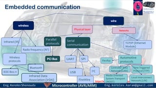
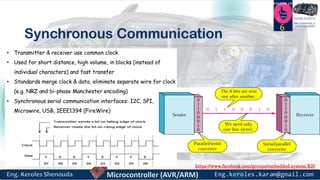
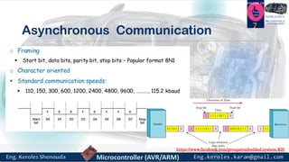
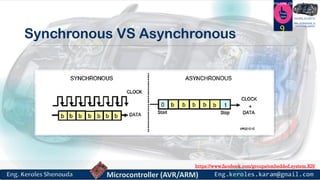
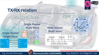
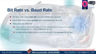
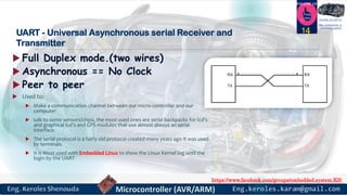
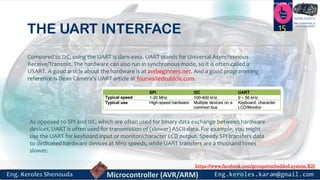
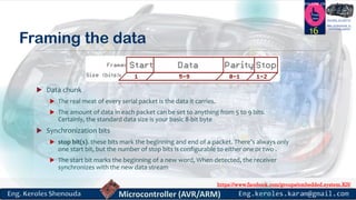
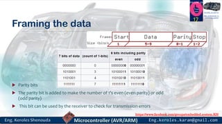
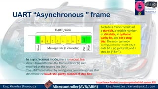
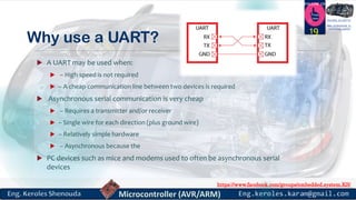
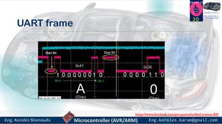
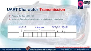
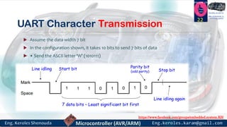
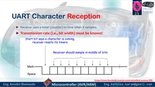
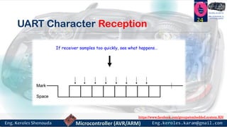
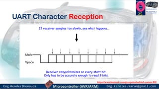
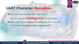
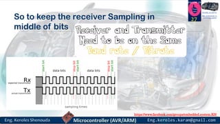
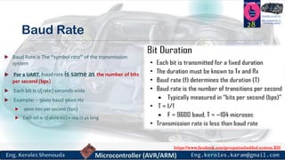
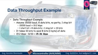
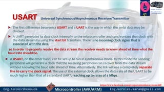
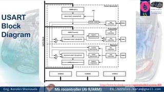
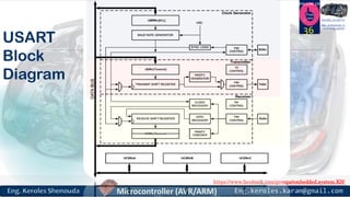
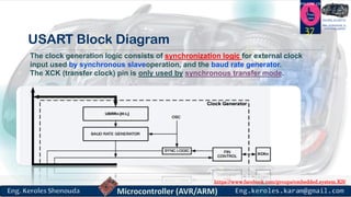
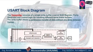
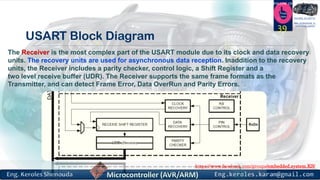
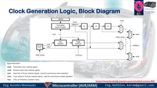
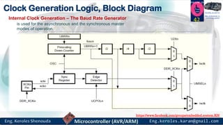
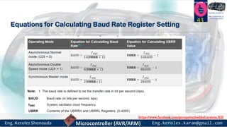
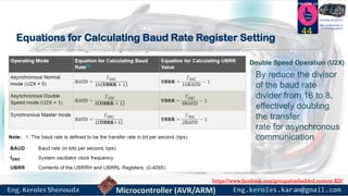
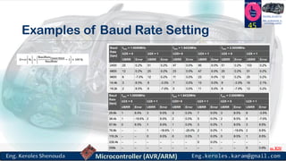
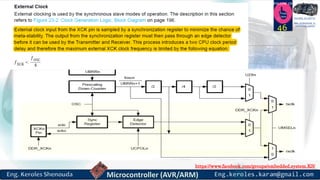
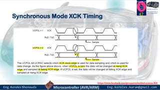
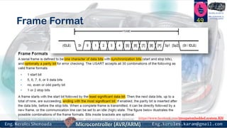
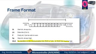
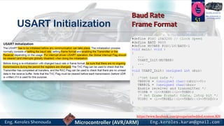
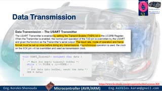
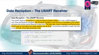
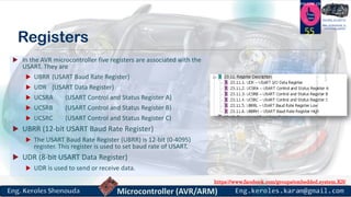
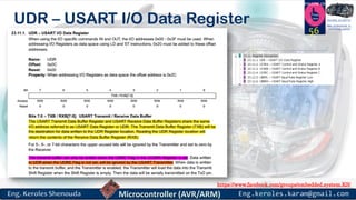
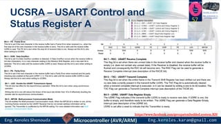
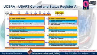
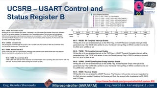
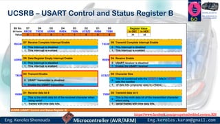
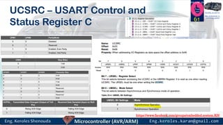
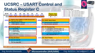
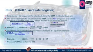
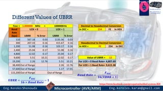
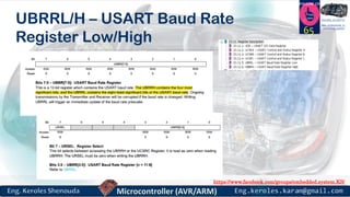
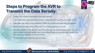
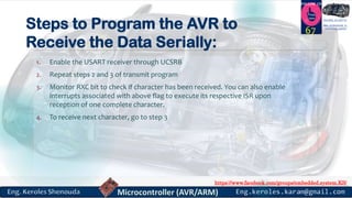
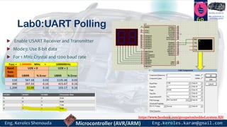
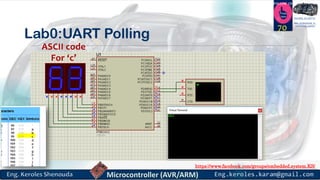
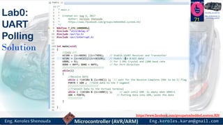
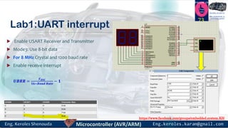
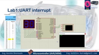
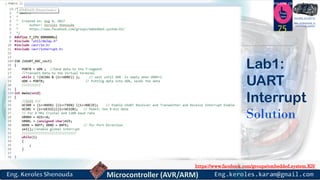
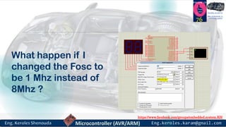
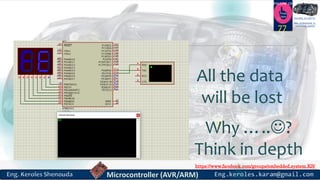
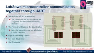
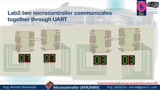
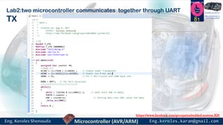
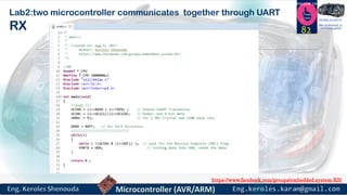
https://www.facebook.com/groups/embedded.system.KS/
Follow us
Press
here
#LEARN_IN DEPTH
#Be_professional_in
embedded_system
Embedded System
PART 7 (UART)
ENG.KEROLES SHENOUDA
1
https://www.facebook.com/groups/embedded.system.KS/
Follow us
Press
here
#LEARN_IN DEPTH
#Be_professional_in
embedded_system
Main Concepts
2
https://www.facebook.com/groups/embedded.system.KS/
Follow us
Press
here
#LEARN_IN DEPTH
#Be_professional_in
embedded_system
Embedded communication
3
Physical layer Networks
Infrared (IR)
Radio frequency (RF)
I2CUSB
FireWire
Serial
communication
SPIUART
Time Triggered
Protocol (TTP)
Local Interconnect
Network (LIN)
Media Oriented
System Transport
(MOST)
Controller Area
Network (CAN)
Automotive
protocols
TCP/IP (Ethernet
Module)
Wireless
protocols
Bluetooth
Infrared Data
Association (IrDA)
IEEE 802.11
FlexRay
https://www.facebook.com/groups/embedded.system.KS/
Follow us
Press
here
#LEARN_IN DEPTH
#Be_professional_in
embedded_system
Simplex, Half-duplex, Full-duplex
4
https://www.facebook.com/groups/embedded.system.KS/
Follow us
Press
here
#LEARN_IN DEPTH
#Be_professional_in
embedded_system
Serial Vs Parallel
5
https://www.facebook.com/groups/embedded.system.KS/
Follow us
Press
here
#LEARN_IN DEPTH
#Be_professional_in
embedded_system
Synchronous Communication
6
https://www.facebook.com/groups/embedded.system.KS/
Follow us
Press
here
#LEARN_IN DEPTH
#Be_professional_in
embedded_system
Asynchronous Communication
7
https://www.facebook.com/groups/embedded.system.KS/
Follow us
Press
here
#LEARN_IN DEPTH
#Be_professional_in
embedded_system
Asynchronous
8
https://www.facebook.com/groups/embedded.system.KS/
Follow us
Press
here
#LEARN_IN DEPTH
#Be_professional_in
embedded_system
Synchronous VS Asynchronous
9
https://www.facebook.com/groups/embedded.system.KS/
Follow us
Press
here
#LEARN_IN DEPTH
#Be_professional_in
embedded_system
Single ended vs differential
10
https://www.facebook.com/groups/embedded.system.KS/
Follow us
Press
here
#LEARN_IN DEPTH
#Be_professional_in
embedded_system
TX/RX relation
11
Single Master
Single Slave
Single Master
Multi Slave Multi Master
Multi Slave
https://www.facebook.com/groups/embedded.system.KS/
Follow us
Press
here
#LEARN_IN DEPTH
#Be_professional_in
embedded_system
Bit Rate vs. Baud Rate
 Bit Rate: how many data bits are transmitted per second?
 Baud Rate: how many symbols are transmitted per second?
 These may be different
 Extra symbols (channel changes) may be inserted for framing, error detection,
acknowledgment, etc. These reduce the bit rate
 A single symbol might encode more than one bit. This increases the bit rate.
12
https://www.facebook.com/groups/embedded.system.KS/
Follow us
Press
here
#LEARN_IN DEPTH
#Be_professional_in
embedded_system
UART
“Universal asynchronous receiver-transmitter”
13
https://www.facebook.com/groups/embedded.system.KS/
Follow us
Press
here
#LEARN_IN DEPTH
#Be_professional_in
embedded_system
UART - Universal Asynchronous serial Receiver and
Transmitter
 Full Duplex mode.(two wires)
 Asynchronous == No Clock
 Peer to peer
 Used to:
 Make a communication channel between our micro-controller and our
computer
 talk to some sensors/chips, the most used ones are serial backpacks for lcd’s
and graphical lcd’s and GPS modules that use almost always an serial
interface.
 The serial protocol is a fairly old protocol created many years ago it was used
by terminals
 It is Most used with Embedded Linux to show the Linux Kernel log until the
login by the UART
14
https://www.facebook.com/groups/embedded.system.KS/
Follow us
Press
here
#LEARN_IN DEPTH
#Be_professional_in
embedded_system
THE UART INTERFACE 15
Compared to I2C, using the UART is darn-easy. UART stands for Universal Asynchronous
Receive/Transmit. The hardware can also run in synchronous mode, so it is often called a
USART. A good article about the hardware is at avrbeginners.net. And a good programming
reference is Dean Camera’s UART article at fourwalledcubicle.com.
As opposed to SPI and I2C, which are often used for binary data exchange between hardware
devices, UART is often used for transmission of (slower) ASCII data. For example, you might
use the UART for keyboard input or monitor/character LCD output. Speedy SPI transfers data
to dedicated hardware devices at MHz speeds, while UART transfers are a thousand times
slower.
https://www.facebook.com/groups/embedded.system.KS/
Follow us
Press
here
#LEARN_IN DEPTH
#Be_professional_in
embedded_system
Framing the data
 Data chunk
 The real meat of every serial packet is the data it carries.
 The amount of data in each packet can be set to anything from 5 to 9 bits.
Certainly, the standard data size is your basic 8-bit byte
 Synchronization bits
 stop bit(s). these bits mark the beginning and end of a packet. There’s always only
one start bit, but the number of stop bits is configurable to either one or two .
 The start bit marks the beginning of a new word, When detected, the receiver
synchronizes with the new data stream
16
https://www.facebook.com/groups/embedded.system.KS/
Follow us
Press
here
#LEARN_IN DEPTH
#Be_professional_in
embedded_system
Framing the data
 Parity bits
 The parity bit is added to make the number of 1’s even (even parity) or odd
(odd parity)
 This bit can be used by the receiver to check for transmission errors
17
https://www.facebook.com/groups/embedded.system.KS/
Follow us
Press
here
#LEARN_IN DEPTH
#Be_professional_in
embedded_system
UART “Asynchronous ” frame 18
Each data frame consists of
a start bit, a variable number
of data bits, an optional
parity bit, and 1 or 2 stop
bits. The most common
configuration is 1 start bit, 8
data bits, no parity bit, and 1
stop bit (“8N1”).
In asynchronous mode, there is no clock line:
data is transmitted on the transmit line (Tx) and
received on the receive line (Rx).
The UART is initialized by configuring control registers that
determine the baud rate, parity, number of stop bits:
https://www.facebook.com/groups/embedded.system.KS/
Follow us
Press
here
#LEARN_IN DEPTH
#Be_professional_in
embedded_system
Why use a UART?
 A UART may be used when:
 – High speed is not required
 – A cheap communication line between two devices is required
 Asynchronous serial communication is very cheap
 – Requires a transmitter and/or receiver
 – Single wire for each direction (plus ground wire)
 – Relatively simple hardware
 – Asynchronous because the
 PC devices such as mice and modems used to often be asynchronous serial
devices
19
https://www.facebook.com/groups/embedded.system.KS/
Follow us
Press
here
#LEARN_IN DEPTH
#Be_professional_in
embedded_system
UART frame
20
https://www.facebook.com/groups/embedded.system.KS/
Follow us
Press
here
#LEARN_IN DEPTH
#Be_professional_in
embedded_system
UART Character Transmission
 Assume the data width 7 bit
 In the configuration shown, it takes 10 bits to send 7 bits of data
21
https://www.facebook.com/groups/embedded.system.KS/
Follow us
Press
here
#LEARN_IN DEPTH
#Be_professional_in
embedded_system
UART Character Transmission
 Assume the data width 7 bit
 In the configuration shown, it takes 10 bits to send 7 bits of data
 • Send the ASCII letter ‘W’ (1010111)
22
https://www.facebook.com/groups/embedded.system.KS/
Follow us
Press
here
#LEARN_IN DEPTH
#Be_professional_in
embedded_system
UART Character Reception
 Receiver uses a timer (counter) to time when it samples.
 Transmission rate (i.e., bit width) must be known!
23
https://www.facebook.com/groups/embedded.system.KS/
Follow us
Press
here
#LEARN_IN DEPTH
#Be_professional_in
embedded_system
UART Character Reception
24
https://www.facebook.com/groups/embedded.system.KS/
Follow us
Press
here
#LEARN_IN DEPTH
#Be_professional_in
embedded_system
UART Character Reception
25
https://www.facebook.com/groups/embedded.system.KS/
Follow us
Press
here
#LEARN_IN DEPTH
#Be_professional_in
embedded_system
UART Character Reception
 Receiver also verifies that stop bit is ‘1’
 If not, reports “framing error” to host system
 New start bit can appear immediately after stop bit
 Receiver will resynchronize on each start bit
26
https://www.facebook.com/groups/embedded.system.KS/
Follow us
Press
here
#LEARN_IN DEPTH
#Be_professional_in
embedded_system
So to keep the receiver Sampling in
middle of bits
27
https://www.facebook.com/groups/embedded.system.KS/
Follow us
Press
here
#LEARN_IN DEPTH
#Be_professional_in
embedded_system
Baud Rate
 Baud Rate is The “symbol rate” of the transmission
system
 For a UART, baud rate is same as the number of bits
per second (bps)
 Each bit is 1/(rate) seconds wide
 Example: – 9600 baud 9600 Hz
 9600 bits per second (bps)
 Each bit is 1/(9600 Hz) ≈ 104.17 µs long
28
https://www.facebook.com/groups/embedded.system.KS/
Follow us
Press
here
#LEARN_IN DEPTH
#Be_professional_in
embedded_system
Data Throughput Example
29
https://www.facebook.com/groups/embedded.system.KS/
Follow us
Press
here
#LEARN_IN DEPTH
#Be_professional_in
embedded_system
What is the difference between
USART vs UART
30
https://www.facebook.com/groups/embedded.system.KS/
Follow us
Press
here
#LEARN_IN DEPTH
#Be_professional_in
embedded_system
USART Universal Synchronous/Asynchronous Receiver/Transmitter
 The first difference between a USART and a UART is the way in which the serial data may be
clocked.
 A UART generates its data clock internally to the microcontroller and synchronizes that clock with
the data stream by using the start bit transition. There is no incoming clock signal that is
associated with the data,
so in order to properly receive the data stream the receiver needs to know ahead of time what the
baud rate should be.
31
 A USART, on the other hand, can be set up to run in synchronous mode. In this mode the sending
peripheral will generate a clock that the receiving peripheral can recover from the data stream
without knowing the baud rate ahead of time. Alternatively, the link will use a completely separate
line to carry the clock signal. The use of the external clock allows the data rate of the USART to be
much higher than that of a standard UART, reaching up to rates of 4 Mbps.
https://www.facebook.com/groups/embedded.system.KS/
Follow us
Press
here
#LEARN_IN DEPTH
#Be_professional_in
embedded_system
Are USARTs and UARTs the same?
 Technically the answer is no. A USART generally has more capabilities that a
standard UART and the ability to generate clocked data allows the USART to
operate at baud rates well beyond a UART's capabilities.
32
https://www.facebook.com/groups/embedded.system.KS/
Follow us
Press
here
#LEARN_IN DEPTH
#Be_professional_in
embedded_system
UART on Atmega32
33
https://www.facebook.com/groups/embedded.system.KS/
Follow us
Press
here
#LEARN_IN DEPTH
#Be_professional_in
embedded_system
USART - Universal Synchronous and Asynchronous serial Receiver
and Transmitter
34
https://www.facebook.com/groups/embedded.system.KS/
Follow us
Press
here
#LEARN_IN DEPTH
#Be_professional_in
embedded_system
USART
Block
Diagram
35
https://www.facebook.com/groups/embedded.system.KS/
Follow us
Press
here
#LEARN_IN DEPTH
#Be_professional_in
embedded_system
USART
Block
Diagram
36
https://www.facebook.com/groups/embedded.system.KS/
Follow us
Press
here
#LEARN_IN DEPTH
#Be_professional_in
embedded_system
USART Block Diagram
37
The clock generation logic consists of synchronization logic for external clock
input used by synchronous slaveoperation, and the baud rate generator.
The XCK (transfer clock) pin is only used by synchronous transfer mode.
https://www.facebook.com/groups/embedded.system.KS/
Follow us
Press
here
#LEARN_IN DEPTH
#Be_professional_in
embedded_system
USART Block Diagram
38
The Transmitter consists of a single write buffer, a serial Shift Register, Parity
Generator and control logic for handling different serial frame formats.
The write buffer allows a continuous transfer of data without any delay between
frames
https://www.facebook.com/groups/embedded.system.KS/
Follow us
Press
here
#LEARN_IN DEPTH
#Be_professional_in
embedded_system
USART Block Diagram
39
The Receiver is the most complex part of the USART module due to its clock and data recovery
units. The recovery units are used for asynchronous data reception. Inaddition to the recovery
units, the Receiver includes a parity checker, control logic, a Shift Register and a
two level receive buffer (UDR). The Receiver supports the same frame formats as the
Transmitter, and can detect Frame Error, Data OverRun and Parity Errors.
https://www.facebook.com/groups/embedded.system.KS/
Follow us
Press
here
#LEARN_IN DEPTH
#Be_professional_in
embedded_system
Clock Generation
40
https://www.facebook.com/groups/embedded.system.KS/
Follow us
Press
here
#LEARN_IN DEPTH
#Be_professional_in
embedded_systemClock Generation Logic, Block Diagram 41
https://www.facebook.com/groups/embedded.system.KS/
Follow us
Press
here
#LEARN_IN DEPTH
#Be_professional_in
embedded_system
Clock Generation Logic, Block Diagram
42Internal Clock Generation – The Baud Rate Generator
is used for the asynchronous and the synchronous master
modes of operation.
https://www.facebook.com/groups/embedded.system.KS/
Follow us
Press
here
#LEARN_IN DEPTH
#Be_professional_in
embedded_system
Equations for Calculating Baud Rate Register Setting
43
https://www.facebook.com/groups/embedded.system.KS/
Follow us
Press
here
#LEARN_IN DEPTH
#Be_professional_in
embedded_system
Equations for Calculating Baud Rate Register Setting
44
Double Speed Operation (U2X)
By reduce the divisor
of the baud rate
divider from 16 to 8,
effectively doubling
the transfer
rate for asynchronous
communication
https://www.facebook.com/groups/embedded.system.KS/
Follow us
Press
here
#LEARN_IN DEPTH
#Be_professional_in
embedded_system
Examples of Baud Rate Setting
45
https://www.facebook.com/groups/embedded.system.KS/
Follow us
Press
here
#LEARN_IN DEPTH
#Be_professional_in
embedded_system
46
https://www.facebook.com/groups/embedded.system.KS/
Follow us
Press
here
#LEARN_IN DEPTH
#Be_professional_in
embedded_system
Synchronous Mode XCK Timing 47
https://www.facebook.com/groups/embedded.system.KS/
Follow us
Press
here
#LEARN_IN DEPTH
#Be_professional_in
embedded_system
Frame Formats
48
https://www.facebook.com/groups/embedded.system.KS/
Follow us
Press
here
#LEARN_IN DEPTH
#Be_professional_in
embedded_system
Frame Format 49
https://www.facebook.com/groups/embedded.system.KS/
Follow us
Press
here
#LEARN_IN DEPTH
#Be_professional_in
embedded_system
Frame Format
50
https://www.facebook.com/groups/embedded.system.KS/
Follow us
Press
here
#LEARN_IN DEPTH
#Be_professional_in
embedded_system
USART Initialization
51
https://www.facebook.com/groups/embedded.system.KS/
Follow us
Press
here
#LEARN_IN DEPTH
#Be_professional_in
embedded_system
Data Transmission
52
https://www.facebook.com/groups/embedded.system.KS/
Follow us
Press
here
#LEARN_IN DEPTH
#Be_professional_in
embedded_system
Data Reception – The USART Receiver
53
https://www.facebook.com/groups/embedded.system.KS/
Follow us
Press
here
#LEARN_IN DEPTH
#Be_professional_in
embedded_system
Register Description
54
https://www.facebook.com/groups/embedded.system.KS/
Follow us
Press
here
#LEARN_IN DEPTH
#Be_professional_in
embedded_system
Registers
55
 In the AVR microcontroller five registers are associated with the
USART. They are
 UBRR (USART Baud Rate Register)
 UDR (USART Data Register)
 UCSRA (USART Control and Status Register A)
 UCSRB (USART Control and Status Register B)
 UCSRC (USART Control and Status Register C)
 UBRR (12-bit USART Baud Rate Register)
 The USART Baud Rate Register (UBRR) is 12-bit (0-4095)
register. This register is used to set baud rate of USART.
 UDR (8-bit USART Data Register)
 UDR is used to send or receive data.
https://www.facebook.com/groups/embedded.system.KS/
Follow us
Press
here
#LEARN_IN DEPTH
#Be_professional_in
embedded_system
UDR – USART I/O Data Register
56
https://www.facebook.com/groups/embedded.system.KS/
Follow us
Press
here
#LEARN_IN DEPTH
#Be_professional_in
embedded_system
UCSRA – USART Control and
Status Register A
57
https://www.facebook.com/groups/embedded.system.KS/
Follow us
Press
here
#LEARN_IN DEPTH
#Be_professional_in
embedded_system
UCSRA – USART Control and Status Register A 58
Bit No. D7 D6 D5 D4 D3 D2 D1 D0 Register Value
Bit Name RXC TXC UDRE FE DOR PE U2X MPCM In DEC In HEX
Value 0 0 0 0 0 0 0 0 00 00
RXC
D7 USART Receive Complete
TXC
D6 USART Transmit Complete
0 Receive buffer is empty 0
Receive buffer is empty so transmit complete
interrupt is executed
1 There is new data in the receive buffer 1
Entire frame in the transmit shift register has
been transmitted
UDRE
D5 USART Data Register Empty
FE
D4 Frame Error
0 Wait, do not write to UDR 0 No frame error
1 Tramsmit data buffer is empty 1 Frame error has occurred
DOR
D3 Data Over Run
PE
D2 Parity Error
0 No Data Over Run 0 No Paroty Error
1 Data over run is detected 1 Parity Error is detected
U2X
D1 Double the USART Transmission Speed
MPCM
D0 Multi-processor Communication Mode
0 Single Baud Rate 0 Disable Multi-processor Communication Mode
1 Double Date Transfer rate for Asynchronous Communication 1 Enable Multi-processor Communication Mode
UCSRA (USART Control and Status Register A)
https://www.facebook.com/groups/embedded.system.KS/
Follow us
Press
here
#LEARN_IN DEPTH
#Be_professional_in
embedded_system
UCSRB – USART Control and
Status Register B
59
https://www.facebook.com/groups/embedded.system.KS/
Follow us
Press
here
#LEARN_IN DEPTH
#Be_professional_in
embedded_system
UCSRB – USART Control and Status Register B
60
Bit No. D7 D6 D5 D4 D3 D2 D1 D0 Register Value
Bit Name RXCIE TXCIE UDRIE RXEN TXEN UCSZ2 RXB8 TXB8 In DEC In HEX
Value 0 0 0 1 1 0 0 0 24 18
RXCIE
D7 Receive Complete Interrupt Enable
TXCIE
D6 Transmit Complete Interrupt Enable
0 This Interrupt is disabled 0 This Interrupt is disabled
1 This interrupt is enabled 1 This interrupt is enabled
UDRIE
D5 Data Register Empty Interrupt Enable
RXEN
D4 Receive Enable
0 This Interrupt is disabled 0 USART receiver is disabled
1 This interrupt is enabled 1 Enable the USART receiver
TXEN
D3 Transmit Enable
UCSZ2
D2 Character Size
0 USART transmitter is disabled 0
This bit combined with the UCSZ1:0 bits in UCSRC
sets the number
1 Enable the USART transmitter 1 of data bits (character size) in a frame.
RXB8
D1 Receive data bit 8
TXB8
D0 Transmit data bit 8
0
This is the ninth data bit of the received character when
using serial
0
This is the ninth data bit of the transmitted character
when using
1 frames with nine data bits. 1 serial frames with nine data bits.
UCSRB (USART Control and Status Register B)
https://www.facebook.com/groups/embedded.system.KS/
Follow us
Press
here
#LEARN_IN DEPTH
#Be_professional_in
embedded_system
UCSRC – USART Control and
Status Register C 61
https://www.facebook.com/groups/embedded.system.KS/
Follow us
Press
here
#LEARN_IN DEPTH
#Be_professional_in
embedded_system
UCSRC – USART Control and
Status Register C 62
Bit No. D7 D6 D5 D4 D3 D2 D1 D0 Register Value
Bit Name URSEL UMSEL UPM1 UPM0 USBS UCSZ1 UCSZ0 UCPOL In DEC In HEX
Value 0 0 0 0 0 1 1 0 06 6
URSEL D7
Register Select UBRRH or UCSRC because both
have same I/O address
UMSEL D6 USART Mode Select
0 UBRRH Register is Selected 0 Asynchronous operation
1 UCSRC register is selected 1 Synchronous operation
UPM1:0 D5 D4 Parity Mode UCSZ1:0 D2 D1 Character Size
0 0 No Parity 0 0 If UCFZ2=0, Character Size = 5
0 1 Reserved 0 1 If UCFZ2=0, Character Size = 6
1 0 Even Parity 1 0 If UCFZ2=0, Character Size = 7
1 1 Odd Parity 1 1
If UCFZ2=0, Character Size = 8
else Character Size = 9
USBS D3 Stop Bit Select UCPOL D0 Clock Polarity
0 Use one stop bit 0 This bit is used for synchronous mode only
1 Use two stop bits 1
UCSRC (USART Control and Status Register C)
https://www.facebook.com/groups/embedded.system.KS/
Follow us
Press
here
#LEARN_IN DEPTH
#Be_professional_in
embedded_system
UBRR (USART Baud Rate Register)
 For a given crystal frequency, the value loaded into the UBRR decides the baud rate.
 The relation between the value loaded into UBBR and the Fosc (frequency of oscillator
connected to the XTAL1 and XTAL2 pins) is dictated by the following formula:
𝑩𝒂𝒖𝒅 𝑹𝒂𝒕𝒆 =
𝑭 𝑶𝑺𝑪
𝟏𝟔(𝑼𝑩𝑹𝑹+𝟏)
 Example: 𝑩𝒂𝒖𝒅 𝑹𝒂𝒕𝒆 =
𝟕𝟑𝟕𝟐𝟖𝟎𝟎
𝟏𝟔(𝟒𝟕+𝟏)
=
𝟕𝟑𝟕𝟐𝟖𝟎𝟎
𝟕𝟔𝟖
= 𝟗𝟔𝟎𝟎
 To get the X value for different baud rates we can solve the equation as follows:
𝑼𝑩𝑹𝑹 =
𝑭 𝑶𝑺𝑪
𝟏𝟔×𝑩𝒂𝒖𝒅 𝑹𝒂𝒕𝒆
− 𝟏
 Example: 𝑼𝑩𝑹𝑹 =
𝟕𝟑𝟕𝟐𝟖𝟎𝟎
𝟏𝟔×𝟗𝟔𝟎𝟎
− 𝟏 = 𝟒𝟖 − 𝟏 = 𝟒𝟕
 The value of UBRR can be from 0 to 4095.
For U2X = 1
Replace 16 with 8
https://www.facebook.com/groups/embedded.system.KS/
Follow us
Press
here
#LEARN_IN DEPTH
#Be_professional_in
embedded_system
Different Values of UBRR
Fosc = 1.000000 MHz = 1000000Hz Decimal to Hexadecimal Conversion
Baud
Rate
(bps)
U2X = 0 U2X = 1 In DEC = 254 FE In HEX
UBRR % Error UBRR % Error
110 567.18 0.03 1135.36 0.03
300 207.33 0.16 415.67 0.16 Hexadecimal to Decimal Conversion
1,200 51.08 0.16 103.17 0.16 In HEX = FE 254 In DEC
2,400 25.04 0.17 51.08 0.16
4,800 12.02 0.17 25.04 0.17
9,600 5.51 10.21 12.02 0.17 Value of UBRR = 12
19,200 2.26 12.76 5.51 10.21 For U2X = 0 Baud Rate= 4,807.69
38,400 Out of Range 2.26 12.76 For U2X = 1 Baud Rate= 9,615.38
57,600 Out of Range 1.17 17.01
115,200 Out of Range Out of Range
𝑼𝑩𝑹𝑹 =
𝑭 𝑶𝑺𝑪
𝟏𝟔 × 𝑩𝒂𝒖𝒅 𝑹𝒂𝒕𝒆
− 𝟏
𝑩𝒂𝒖𝒅 𝑹𝒂𝒕𝒆 =
𝑭 𝑶𝑺𝑪
𝟏𝟔(𝑼𝑩𝑹𝑹 + 𝟏)
https://www.facebook.com/groups/embedded.system.KS/
Follow us
Press
here
#LEARN_IN DEPTH
#Be_professional_in
embedded_system
UBRRL/H – USART Baud Rate
Register Low/High
65
https://www.facebook.com/groups/embedded.system.KS/
Follow us
Press
here
#LEARN_IN DEPTH
#Be_professional_in
embedded_systemSteps to Program the AVR to
Transmit the Data Serially:
1. Enable the USART transmitter through UCSRB
2. Use 8 data bits, asynchronous mode, 1 stop bit and no parity through UCSRC
3. Calculate the value to be loaded in UBRR for a desired baud rate generation
4. Write the character into UDR which is to be transmitted serially
5. Monitor UDRE or TXC bits to check if character has been transmitted. You can
also enable interrupts associated with above flags to execute their respective
ISRs upon completion of transmission.
6. To transmit next character, go to step 4
66
https://www.facebook.com/groups/embedded.system.KS/
Follow us
Press
here
#LEARN_IN DEPTH
#Be_professional_in
embedded_systemSteps to Program the AVR to
Receive the Data Serially:
1. Enable the USART receiver through UCSRB
2. Repeat steps 2 and 3 of transmit program
3. Monitor RXC bit to check if character has been received. You can also enable
interrupts associated with above flag to execute its respective ISR upon
reception of one complete character.
4. To receive next character, go to step 3
67
https://www.facebook.com/groups/embedded.system.KS/
Follow us
Press
here
#LEARN_IN DEPTH
#Be_professional_in
embedded_system
Lab0:UART Polling
68
https://www.facebook.com/groups/embedded.system.KS/
Follow us
Press
here
#LEARN_IN DEPTH
#Be_professional_in
embedded_system
Lab0:UART Polling
 Enable USART Receiver and Transmitter
 Mode3: Use 8-bit data
 For 1 MHz Crystal and 1200 baud rate
69
https://www.facebook.com/groups/embedded.system.KS/
Follow us
Press
here
#LEARN_IN DEPTH
#Be_professional_in
embedded_system
Lab0:UART Polling
70
ASCII code
For ‘c’
https://www.facebook.com/groups/embedded.system.KS/
Follow us
Press
here
#LEARN_IN DEPTH
#Be_professional_in
embedded_system
Lab0:
UART
Polling
Solution
71
https://www.facebook.com/groups/embedded.system.KS/
Follow us
Press
here
#LEARN_IN DEPTH
#Be_professional_in
embedded_system
Lab1:UART Interrupt
72
https://www.facebook.com/groups/embedded.system.KS/
Follow us
Press
here
#LEARN_IN DEPTH
#Be_professional_in
embedded_system
Lab1:UART interrupt
 Enable USART Receiver and Transmitter
 Mode3: Use 8-bit data
 For 8 MHz Crystal and 1200 baud rate
 Enable receive interrupt
73
𝑼𝑩𝑹𝑹 =
𝑭 𝑶𝑺𝑪
𝟏𝟔×𝑩𝒂𝒖𝒅 𝑹𝒂𝒕𝒆
− 𝟏
https://www.facebook.com/groups/embedded.system.KS/
Follow us
Press
here
#LEARN_IN DEPTH
#Be_professional_in
embedded_system
Lab1:UART interrupt
74
https://www.facebook.com/groups/embedded.system.KS/
Follow us
Press
here
#LEARN_IN DEPTH
#Be_professional_in
embedded_system
75
Lab1:
UART
Interrupt
Solution
https://www.facebook.com/groups/embedded.system.KS/
Follow us
Press
here
#LEARN_IN DEPTH
#Be_professional_in
embedded_system
What happen if I
changed the Fosc to
be 1 Mhz instead of
8Mhz ?
76
https://www.facebook.com/groups/embedded.system.KS/
Follow us
Press
here
#LEARN_IN DEPTH
#Be_professional_in
embedded_system
77
All the data
will be lost
Why …..?
Think in depth
https://www.facebook.com/groups/embedded.system.KS/
Follow us
Press
here
#LEARN_IN DEPTH
#Be_professional_in
embedded_system
Lab2:two microcontroller
communicates together
through UART
78
https://www.facebook.com/groups/embedded.system.KS/
Follow us
Press
here
#LEARN_IN DEPTH
#Be_professional_in
embedded_systemLab2:two microcontroller communicates
together through UART
 Transmitter will act as a counter,
 The count Value will be displayed on the
7-segment and also will be sent to the
receiver.
 The receiver will receive the Count value
 From the transmitter and ten will display
it on its 7-segment
 Crystal Frequency = 1MHz
 For 1200 Baud Rate
 Use 8-bit data
79
https://www.facebook.com/groups/embedded.system.KS/
Follow us
Press
here
#LEARN_IN DEPTH
#Be_professional_in
embedded_system
Lab2:two microcontroller communicates
together through UART
80
https://www.facebook.com/groups/embedded.system.KS/
Follow us
Press
here
#LEARN_IN DEPTH
#Be_professional_in
embedded_system
Lab2:two microcontroller communicates together through UART
TX 81
https://www.facebook.com/groups/embedded.system.KS/
Follow us
Press
here
#LEARN_IN DEPTH
#Be_professional_in
embedded_system
Lab2:two microcontroller communicates together through UART
RX 82
https://www.facebook.com/groups/embedded.system.KS/
Follow us
Press
here
#LEARN_IN DEPTH
#Be_professional_in
embedded_system
How to transfer the data between
AVR and PC using normal
asynchronous mode ?
83
https://www.facebook.com/groups/embedded.system.KS/
Follow us
Press
here
#LEARN_IN DEPTH
#Be_professional_in
embedded_system
MAX232 – Level Converter IC
 The serial port of computer
sends/receives data serially
at logic levels between -12
to +12V whereas,
microcontroller works at
logic levels between 0 to 5V
(TTL). So we need a RS-232
to TTL and TTL to RS-232
converter and this is done
by using RS-232 Level
Converter IC, MAX232
between PC and ATmega32.
84
https://www.facebook.com/groups/embedded.system.KS/
Follow us
Press
here
#LEARN_IN DEPTH
#Be_professional_in
embedded_system
FT232 (UART to USB)
85
https://www.facebook.com/groups/embedded.system.KS/
Follow us
Press
here
#LEARN_IN DEPTH
#Be_professional_in
embedded_system
USART Driver
HTTPS://GITHUB.COM/KEROLES/EMBEDDED_SYSTEM/TREE/MASTER/ATMEGA32
_DRIVERS/ATMEGA32_DRIVERS/USART
86
https://www.facebook.com/groups/embedded.system.KS/
Follow us
Press
here
#LEARN_IN DEPTH
#Be_professional_in
embedded_system
87
USART.h
https://www.facebook.com/groups/embedded.system.KS/
Follow us
Press
here
#LEARN_IN DEPTH
#Be_professional_in
embedded_system
88
USART.h
https://www.facebook.com/groups/embedded.system.KS/
Follow us
Press
here
#LEARN_IN DEPTH
#Be_professional_in
embedded_system
89
USART.c
https://www.facebook.com/groups/embedded.system.KS/
Follow us
Press
here
#LEARN_IN DEPTH
#Be_professional_in
embedded_system
90
USART.c
https://www.facebook.com/groups/embedded.system.KS/
Follow us
Press
here
#LEARN_IN DEPTH
#Be_professional_in
embedded_system
91
USART.c
https://www.facebook.com/groups/embedded.system.KS/
Follow us
Press
here
#LEARN_IN DEPTH
#Be_professional_in
embedded_system
92
USART.c
https://www.facebook.com/groups/embedded.system.KS/
Follow us
Press
here
#LEARN_IN DEPTH
#Be_professional_in
embedded_system
93
USART.c
https://www.facebook.com/groups/embedded.system.KS/
Follow us
Press
here
#LEARN_IN DEPTH
#Be_professional_in
embedded_system
94
USART.c
https://www.facebook.com/groups/embedded.system.KS/
Follow us
Press
here
#LEARN_IN DEPTH
#Be_professional_in
embedded_system
95
USART.c
https://www.facebook.com/groups/embedded.system.KS/
Follow us
Press
here
#LEARN_IN DEPTH
#Be_professional_in
embedded_system
Repeat the TX in LAB2 by using the
USART Driver
96
https://www.facebook.com/groups/embedded.system.KS/
Follow us
Press
here
#LEARN_IN DEPTH
#Be_professional_in
embedded_system
97
https://www.facebook.com/groups/embedded.system.KS/
Follow us
Press
here
#LEARN_IN DEPTH
#Be_professional_in
embedded_system
References
 https://www.newbiehack.com/MicrocontrollersABeginnersGuideIntroductiona
ndInterfacinganLCD.aspx
 http://www.slideshare.net/MathivananNatarajan/asynchronous-serial-data-
communication-and-standards
 https://www.slideshare.net/AnkitSingh13/uart-32550652
 the avr microcontroller and embedded. System using assembly and c.
Muhammad Ali Mazidi
98
https://www.facebook.com/groups/embedded.system.KS/
Follow us
Press
here
#LEARN_IN DEPTH
#Be_professional_in
embedded_system
99

Microcontroller part 7_v1