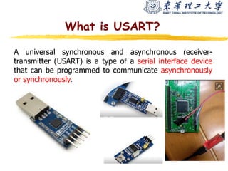
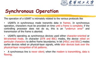
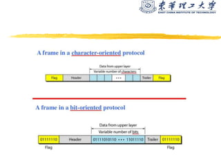
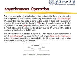
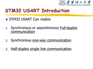
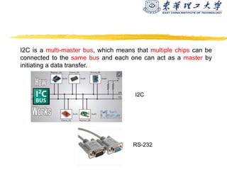
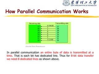
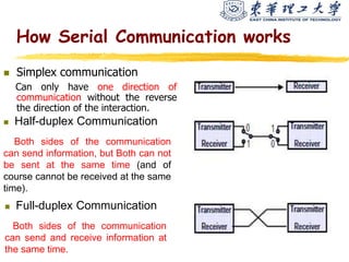
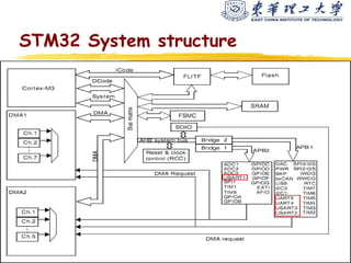
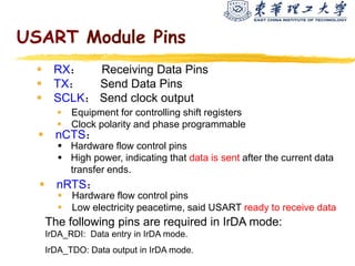
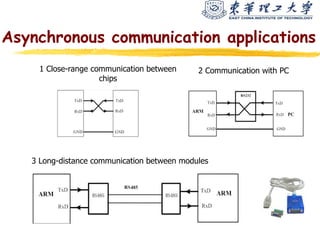
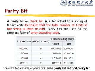
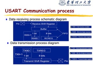
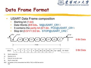
STM32 USART
(Universal Synchronous/Asynchronous
Receiver/Transmitter)
What is USART?
A universal synchronous and asynchronous receiver-
transmitter (USART) is a type of a serial interface device
that can be programmed to communicate asynchronously
or synchronously.
Synchronous Operation
The operation of a USART is intimately related to the various protocols like
• USARTs in synchronous mode transmits data in frames. In synchronous
operation, characters must be provided on time until a frame is complete; if the
controlling processor does not do so, this is an "underrun error" and
transmission of the frame is aborted.
• USARTs operating as synchronous devices used either character-oriented or
bit-oriented mode. In character (STR and BSC) modes, the device relied on
particular characters to define frame boundaries; in bit (HDLC and SDLC) modes
earlier devices relied on physical-layer signals, while later devices took over the
physical-layer recognition of bit patterns.
• A synchronous line is never silent; when the modem is transmitting, data is
flowing.
Asynchronous Operation
Asynchronous serial communication in its most primitive form is implemented
over a symmetric pair of wires connecting two devices e.g. host and target.
Whenever the host has data to send to the target, it does so by sending an
encoded bit stream over its transmit (TX) wire; this data is received by the
target over its receive (RX) wire. Similarly, when the target has data to send to
the host it transmits the encoded bit stream over its TX wire and this data is
received by the host over its RX wire.
This arrangement is illustrated in Figure 5.1. This mode of communications is
called “asynchronous” because the host and target share no time reference.
Instead, temporal properties are encoded in the bit stream by the transmitter
and must be decoded by the receiver.
STM32 USART Introduction
 STM32 USART Can realize
1. Synchronous or asynchronous Full-duplex
communication
2. Synchronous one-way communication
3. Half-duplex single line communication.
Communication Interface
 For exchanging information with another IC or
external devices, e.g. I2C,RS-232,USB,Ethernet…
 Serial communication:
A single bit is transferred at a time
 Synchronization: A clock signal is sent along with the data; the device
that generates the clock is called the master and other devices are
slaves.
 Asynchronous: No clock is transmitted, fewer wires.
 Parallel communication:
Multiple bits are transferred at a time
I2C is a multi-master bus, which means that multiple chips can be
connected to the same bus and each one can act as a master by
initiating a data transfer.
RS-232
I2C
How Parallel Communication Works
In parallel communication an entire byte of data is transmitted at a
time. That is each bit has dedicated line. Thus for 8-bit data transfer
we need 8 dedicated lines as shown above.
How Serial Communication works
 Simplex communication
Can only have one direction of
communication without the reverse
the direction of the interaction.
 Half-duplex Communication
Both sides of the communication
can send information, but Both can not
be sent at the same time (and of
course cannot be received at the same
time).
 Full-duplex Communication
Both sides of the communication
can send and receive information at
the same time.
STM32 System structure
What is UART?
A universal asynchronous receiver-transmitter (UART) is a computer
hardware device for asynchronous serial communication in which the
data format and transmission speeds are configurable.
The electric signaling levels and methods are handled by a driver circuit
external to the UART.
A UART is usually an individual (or part of an) integrated circuit (IC)
used for serial communications over a computer or peripheral device
serial port. UARTs are now commonly included in microcontrollers. A
related device, the universal synchronous and asynchronous receiver-
transmitter (USART) also supports synchronous operation.
 RX: Receiving Data Pins
 TX: Send Data Pins
 SCLK: Send clock output
 Equipment for controlling shift registers
 Clock polarity and phase programmable
 nCTS:
 Hardware flow control pins
 High power, indicating that data is sent after the current data
transfer ends.
 nRTS:
 Hardware flow control pins
 Low electricity peacetime, said USART ready to receive data
USART Module Pins
The following pins are required in IrDA mode:
IrDA_RDI: Data entry in IrDA mode.
IrDA_TDO: Data output in IrDA mode.
Asynchronous communication applications
1 Close-range communication between
chips
2 Communication with PC
3 Long-distance communication between modules
Parity Bit
A parity bit or check bit, is a bit added to a string of
binary code to ensure that the total number of 1-bits in
the string is even or odd. Parity bits are used as the
simplest form of error detecting code.
There are two variants of parity bits: even parity bit and odd parity bit.
USART Communication process
 Data receiving process schematic diagram
 Data transmission process diagram
 USART Data Frame composition
 Starting bit (1-bit)
 Data Words (8/9 bits,M@USART_CR1)
 It contains the parity bit (0/1-bit,PCE@USART_CR1)
 Stop bit (0.5/1/1.5/2 bit,STOP@USART_CR2)
8 Bit Data
9 Bit Data
Data Frame Format
USART Interrupt Request
In a computer, an interrupt request (or IRQ) is
hardware signal sent to the processor that
temporarily stops a running program and allows
a special program, an interrupt handler, to run
instead.
Advantages of using interrupts-
 No polling or waiting for data
 Background tasks easier
 Fast response
 Reduced chance of overflow errors
 More common for receiving data
2023/1/24 19
In computing, interrupt latency is the time that
passes from when an interrupt is generated to when
the source of the interrupt is serviced.
For many operating systems, devices are serviced/operated
as soon as the device's interrupt handler/ISR is executed.
Interrupt latency
6 STM32's USART.ppt

6 STM32's USART.ppt

  • 1.
  • 2.
    What is USART? Auniversal synchronous and asynchronous receiver- transmitter (USART) is a type of a serial interface device that can be programmed to communicate asynchronously or synchronously.
  • 3.
    Synchronous Operation The operationof a USART is intimately related to the various protocols like • USARTs in synchronous mode transmits data in frames. In synchronous operation, characters must be provided on time until a frame is complete; if the controlling processor does not do so, this is an "underrun error" and transmission of the frame is aborted. • USARTs operating as synchronous devices used either character-oriented or bit-oriented mode. In character (STR and BSC) modes, the device relied on particular characters to define frame boundaries; in bit (HDLC and SDLC) modes earlier devices relied on physical-layer signals, while later devices took over the physical-layer recognition of bit patterns. • A synchronous line is never silent; when the modem is transmitting, data is flowing.
  • 5.
    Asynchronous Operation Asynchronous serialcommunication in its most primitive form is implemented over a symmetric pair of wires connecting two devices e.g. host and target. Whenever the host has data to send to the target, it does so by sending an encoded bit stream over its transmit (TX) wire; this data is received by the target over its receive (RX) wire. Similarly, when the target has data to send to the host it transmits the encoded bit stream over its TX wire and this data is received by the host over its RX wire. This arrangement is illustrated in Figure 5.1. This mode of communications is called “asynchronous” because the host and target share no time reference. Instead, temporal properties are encoded in the bit stream by the transmitter and must be decoded by the receiver.
  • 6.
    STM32 USART Introduction STM32 USART Can realize 1. Synchronous or asynchronous Full-duplex communication 2. Synchronous one-way communication 3. Half-duplex single line communication.
  • 7.
    Communication Interface  Forexchanging information with another IC or external devices, e.g. I2C,RS-232,USB,Ethernet…  Serial communication: A single bit is transferred at a time  Synchronization: A clock signal is sent along with the data; the device that generates the clock is called the master and other devices are slaves.  Asynchronous: No clock is transmitted, fewer wires.  Parallel communication: Multiple bits are transferred at a time
  • 8.
    I2C is amulti-master bus, which means that multiple chips can be connected to the same bus and each one can act as a master by initiating a data transfer. RS-232 I2C
  • 9.
    How Parallel CommunicationWorks In parallel communication an entire byte of data is transmitted at a time. That is each bit has dedicated line. Thus for 8-bit data transfer we need 8 dedicated lines as shown above.
  • 10.
    How Serial Communicationworks  Simplex communication Can only have one direction of communication without the reverse the direction of the interaction.  Half-duplex Communication Both sides of the communication can send information, but Both can not be sent at the same time (and of course cannot be received at the same time).  Full-duplex Communication Both sides of the communication can send and receive information at the same time.
  • 11.
  • 12.
    What is UART? Auniversal asynchronous receiver-transmitter (UART) is a computer hardware device for asynchronous serial communication in which the data format and transmission speeds are configurable. The electric signaling levels and methods are handled by a driver circuit external to the UART. A UART is usually an individual (or part of an) integrated circuit (IC) used for serial communications over a computer or peripheral device serial port. UARTs are now commonly included in microcontrollers. A related device, the universal synchronous and asynchronous receiver- transmitter (USART) also supports synchronous operation.
  • 13.
     RX: ReceivingData Pins  TX: Send Data Pins  SCLK: Send clock output  Equipment for controlling shift registers  Clock polarity and phase programmable  nCTS:  Hardware flow control pins  High power, indicating that data is sent after the current data transfer ends.  nRTS:  Hardware flow control pins  Low electricity peacetime, said USART ready to receive data USART Module Pins The following pins are required in IrDA mode: IrDA_RDI: Data entry in IrDA mode. IrDA_TDO: Data output in IrDA mode.
  • 14.
    Asynchronous communication applications 1Close-range communication between chips 2 Communication with PC 3 Long-distance communication between modules
  • 15.
    Parity Bit A paritybit or check bit, is a bit added to a string of binary code to ensure that the total number of 1-bits in the string is even or odd. Parity bits are used as the simplest form of error detecting code. There are two variants of parity bits: even parity bit and odd parity bit.
  • 16.
    USART Communication process Data receiving process schematic diagram  Data transmission process diagram
  • 17.
     USART DataFrame composition  Starting bit (1-bit)  Data Words (8/9 bits,M@USART_CR1)  It contains the parity bit (0/1-bit,PCE@USART_CR1)  Stop bit (0.5/1/1.5/2 bit,STOP@USART_CR2) 8 Bit Data 9 Bit Data Data Frame Format
  • 18.
    USART Interrupt Request Ina computer, an interrupt request (or IRQ) is hardware signal sent to the processor that temporarily stops a running program and allows a special program, an interrupt handler, to run instead. Advantages of using interrupts-  No polling or waiting for data  Background tasks easier  Fast response  Reduced chance of overflow errors  More common for receiving data
  • 19.
    2023/1/24 19 In computing,interrupt latency is the time that passes from when an interrupt is generated to when the source of the interrupt is serviced. For many operating systems, devices are serviced/operated as soon as the device's interrupt handler/ISR is executed. Interrupt latency