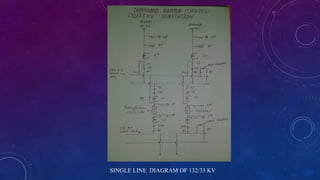
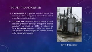
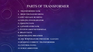
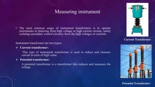
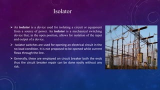
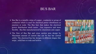
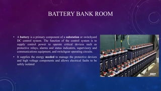
MORADABAD INSTITUTE OF TECHNOLOGY
MORADABAD
Electrical Engineering Department
A
Presentation of Industrial training
on
132/33 KV Substation
SUBMITTED TO :
Mr Maroof Ali
(Assistant professor)
PRESENTED BY:
Name of student:XYZ
Roll No-XXXXXX
CONTENTS
 About 132/33kv substation
 Single line diagram
 Equipments atthe substation
 Power transformer
 Parts of transformer
 Measuring instrument
 Circuit breaker
 Isolator
 Bus coupler
 Relay
 Lightning arrester
 Capacitor bank
 Control room
 Wave trap
 Bus bar
 Bus bar
 Battery bank room
 Conclusion
 Reference
About 132/33kv substation
• A substation is a part of an electrical transmission and distribution system.
Substations transform voltage from high to low, or the reverse, or perform
any of several other important functions.
• To design a 132KV/33KV EHV sub-station where the incoming power is
received at 132 KV from a generating station.
• The power from main bus was fed into a 20MVA transformer which stepped
the voltage down to 33KV.
• The power is then fed into a 33KV bus from which different loads were
tapped.
Single line diagram
• In power engineering a single-line diagram (SLD), also sometimes
called one-line diagram, is a simplified notation for representing a three-
phase power system.
• The one-line diagram has its largest application in power flow studies.
Electrical elements such as circuit breakers, transformers, capacitors, bus
bars, and conductors are shown by standardized schematic symbols.
• Figure shows the single line diagram of power system.
SINGLE LINE DIAGRAM OF 132/33 KV
EQUIPMENTS ATTHE SUBSTATION
 Power transformers
 Current transformer
 Potential transformer
 Isolator
 Circuit breaker
 Bus coupler
 Relay
 Lightning arrestor
 Bus coupler
 Wave trap
POWER TRANSFORMER
 A transformer is a passive electrical device that
transfers electrical energy from one electrical circuit
to another, or multiple circuits.
 A transformer consists of two electrically isolated
coils and operates on Faraday's principal of “mutual
induction”, in which an EMF is induced in
the transformers secondary coil by the magnetic
flux generated by the voltages and currents flowing
in the primary coil winding.
Power Transformer
PARTS OF TRANSFORMER
1. TRANSFORMER TANK
2. HIGH VOLTAGEBUSHING
3. LOW VOLTAGE BUSHING
4.COOLING FINS/RADIATOR
5. COOLING FANS
6. CONSERVATOR TANK
7. SYSTEM GROUNDTERMINAL
8. DRAIN VALVE
9.DEHYDRATING BREATHER
10. OIL TEMPERATURE/PRESSURE GAUGES
11.BUSHING CURRENT TRANSFORMERS
12. CONTROL PANEL
13. SURGE ARRESTERS
Measuring instrument
• The most common usage of instrument transformers is to operate
instruments or metering from high voltage or high current circuits, safely
isolating secondary control circuitry from the high voltages or currents.
Instrument transformer are two types:
 Current transformer:
This type of instrument transformer is used to reduce and measure
current in term of high value.
 Potential transformer:
A potential transformer is a transformer that reduces and measures the
voltage.
Current Transformer
Potential Transformer
Circuit breaker
 A circuit breaker is an automatically
operated electrical switch designed to protect an electrical
circuit from damage caused by excess current from an
overload or short circuit.
 Its basic function is to interrupt current flow after a fault is
detected.
 which operates once and then must be replaced, a circuit
breaker can be reset (either manually or automatically) to
resume normal operation.
Isolator
 An isolator is a device used for isolating a circuit or equipment
from a source of power. An isolator is a mechanical switching
device that, in the open position, allows for isolation of the input
and output of a device.
 Isolator switches are used for opening an electrical circuit in the
no-load condition. It is not proposed to be opened while current
flows through the line.
 Generally, these are employed on circuit breaker both the ends
thus the circuit breaker repair can be done easily without any
risk.
BUS COUPLER
 Bus coupler is a device which is used to couple one bus to the other
without any interruption in power supply and without creating
hazardous arcs.
 Bus coupler is a breaker used to couple two busbars in order to
perform maintenance on other circuit breakers associated with that
busbar.
Relay
 A relay is an electromagnetic switch operated by a relatively
small electric current that can turn on or off a much larger
electric current.
 It works on the principle of an electromagnetic attraction. When
the circuit of the relay senses the fault current, it energises the
electromagnetic field which produces the temporary magnetic
field. Then after it provide trip signal to the circuit breaker and
entire system is protect.
Lightning arrester
 A Lightning Arrester is a device used on electrical power systems and
telecommunications systems to protect the insulation and conductors of the
system from the damaging effects of lightning.
 The arrester provides a low-impedance path to ground for the current from a
lightning strike or transient voltage and then restores to a normal operating
conditions.
CAPACITOR BANK
 As the name implies, a capacitor bank is merely a grouping
of several capacitors of the same rating.
 Capacitor banks may be connected in series or parallel,
depending upon the desired rating. As with an
individual capacitor, banks of capacitors are used to store
electrical energy and condition the flow of that energy.
CONTROL ROOM
 As the name suggest, where we can control the equipment and
view reading of all equipment and also view any types od
abnormal condition.
 The various supervision, control and protection functions are
performed in the substation control room. The relays, protection
and control panels are installed in the controlled room.
WAVE TRAP
 A line trap, also known as wave trap, or high-frequency stopper,
is a maintenance-free parallel resonant circuit, mounted inline on
high-voltage (HV) AC transmission power lines to prevent the
transmission of high frequency (40 kHz to 1000 kHz) carrier
signals of power line communication to unwanted destinations.
 Wave trap is used to create high impedance to the carrier wave
high frequency communication entering in to unwanted
destinations typically substation. It consists of an inductor coil
which is connected in series with the high voltage power system.
BUS BAR
 Bus Bar is a metallic strips of copper , conductor or group of
conductor which is used for electrical power distribution as
junction or node. The Bus bars that makes the electrical
power distribution much easier , less expensive and more
flexible. Bus Bar manufacturered by aluminium and copper.
 The Size of Bus Bar and cross section area design by
Maximum amount of current that can be bus bar carried
safely. The electrical bus bar designs in different shapes like
strips , solid bars or rode and hollow.
BATTERY BANK ROOM
• A battery is a primary component of a substation or switchyard
DC control system. The function of the control system is to
supply control power to operate critical devices such as
protective relays, alarms and status indicators, supervisory and
communications equipment, and switchgear operating circuits.
• It supplies the energy needed to manage the protective devices
and high voltage components and allows electrical faults to be
safely isolated
CONCLUSION
 Electricity plays an important role in our life. At the end of the training, I came to know about
the various parts of substations and how they are operated. Also I learnt about how
transmission is done in various parts of Uttar Pradesh.
 As evident from the ppt, a substation plays a very important role in the transmission system.
That’s why various protective measures are taken to protect the substations from various faults
and its smooth functioning. Power Transmission Corporation of Uttar Pradesh Limited takes
such steps so that a uniform and stable supply of electricity can reach in every part of this
state.
REFERENCE
 https://en.wikipedia.org/wiki/Electrical_substation
 http://www.cromptonusa.com/Potential%20Transformers.pdf
 https://circuitglobe.com/electrical-substation-
equipment.html#:~:text=Lightning%20Arrestor&text=It%20protects%20the%20substation%20equipme
nt,under%20protection%20at%20the%20substation.
 Name of book
Electrical Power generation, transmission and distribution by C.N Singh
 Morden power system analysis by D P kothari
CERTIFICATE
You can add here your certificate
THANK YOU

sub subsation seminar ppt.pptx

  • 1.
    MORADABAD INSTITUTE OFTECHNOLOGY MORADABAD Electrical Engineering Department A Presentation of Industrial training on 132/33 KV Substation SUBMITTED TO : Mr Maroof Ali (Assistant professor) PRESENTED BY: Name of student:XYZ Roll No-XXXXXX
  • 2.
    CONTENTS  About 132/33kvsubstation  Single line diagram  Equipments atthe substation  Power transformer  Parts of transformer  Measuring instrument  Circuit breaker  Isolator  Bus coupler  Relay  Lightning arrester  Capacitor bank  Control room  Wave trap  Bus bar  Bus bar  Battery bank room  Conclusion  Reference
  • 3.
    About 132/33kv substation •A substation is a part of an electrical transmission and distribution system. Substations transform voltage from high to low, or the reverse, or perform any of several other important functions. • To design a 132KV/33KV EHV sub-station where the incoming power is received at 132 KV from a generating station. • The power from main bus was fed into a 20MVA transformer which stepped the voltage down to 33KV. • The power is then fed into a 33KV bus from which different loads were tapped.
  • 4.
    Single line diagram •In power engineering a single-line diagram (SLD), also sometimes called one-line diagram, is a simplified notation for representing a three- phase power system. • The one-line diagram has its largest application in power flow studies. Electrical elements such as circuit breakers, transformers, capacitors, bus bars, and conductors are shown by standardized schematic symbols. • Figure shows the single line diagram of power system.
  • 5.
    SINGLE LINE DIAGRAMOF 132/33 KV
  • 6.
    EQUIPMENTS ATTHE SUBSTATION Power transformers  Current transformer  Potential transformer  Isolator  Circuit breaker  Bus coupler  Relay  Lightning arrestor  Bus coupler  Wave trap
  • 7.
    POWER TRANSFORMER  Atransformer is a passive electrical device that transfers electrical energy from one electrical circuit to another, or multiple circuits.  A transformer consists of two electrically isolated coils and operates on Faraday's principal of “mutual induction”, in which an EMF is induced in the transformers secondary coil by the magnetic flux generated by the voltages and currents flowing in the primary coil winding. Power Transformer
  • 8.
    PARTS OF TRANSFORMER 1.TRANSFORMER TANK 2. HIGH VOLTAGEBUSHING 3. LOW VOLTAGE BUSHING 4.COOLING FINS/RADIATOR 5. COOLING FANS 6. CONSERVATOR TANK 7. SYSTEM GROUNDTERMINAL 8. DRAIN VALVE 9.DEHYDRATING BREATHER 10. OIL TEMPERATURE/PRESSURE GAUGES 11.BUSHING CURRENT TRANSFORMERS 12. CONTROL PANEL 13. SURGE ARRESTERS
  • 9.
    Measuring instrument • Themost common usage of instrument transformers is to operate instruments or metering from high voltage or high current circuits, safely isolating secondary control circuitry from the high voltages or currents. Instrument transformer are two types:  Current transformer: This type of instrument transformer is used to reduce and measure current in term of high value.  Potential transformer: A potential transformer is a transformer that reduces and measures the voltage. Current Transformer Potential Transformer
  • 10.
    Circuit breaker  Acircuit breaker is an automatically operated electrical switch designed to protect an electrical circuit from damage caused by excess current from an overload or short circuit.  Its basic function is to interrupt current flow after a fault is detected.  which operates once and then must be replaced, a circuit breaker can be reset (either manually or automatically) to resume normal operation.
  • 11.
    Isolator  An isolatoris a device used for isolating a circuit or equipment from a source of power. An isolator is a mechanical switching device that, in the open position, allows for isolation of the input and output of a device.  Isolator switches are used for opening an electrical circuit in the no-load condition. It is not proposed to be opened while current flows through the line.  Generally, these are employed on circuit breaker both the ends thus the circuit breaker repair can be done easily without any risk.
  • 12.
    BUS COUPLER  Buscoupler is a device which is used to couple one bus to the other without any interruption in power supply and without creating hazardous arcs.  Bus coupler is a breaker used to couple two busbars in order to perform maintenance on other circuit breakers associated with that busbar.
  • 13.
    Relay  A relayis an electromagnetic switch operated by a relatively small electric current that can turn on or off a much larger electric current.  It works on the principle of an electromagnetic attraction. When the circuit of the relay senses the fault current, it energises the electromagnetic field which produces the temporary magnetic field. Then after it provide trip signal to the circuit breaker and entire system is protect.
  • 14.
    Lightning arrester  ALightning Arrester is a device used on electrical power systems and telecommunications systems to protect the insulation and conductors of the system from the damaging effects of lightning.  The arrester provides a low-impedance path to ground for the current from a lightning strike or transient voltage and then restores to a normal operating conditions.
  • 15.
    CAPACITOR BANK  Asthe name implies, a capacitor bank is merely a grouping of several capacitors of the same rating.  Capacitor banks may be connected in series or parallel, depending upon the desired rating. As with an individual capacitor, banks of capacitors are used to store electrical energy and condition the flow of that energy.
  • 16.
    CONTROL ROOM  Asthe name suggest, where we can control the equipment and view reading of all equipment and also view any types od abnormal condition.  The various supervision, control and protection functions are performed in the substation control room. The relays, protection and control panels are installed in the controlled room.
  • 17.
    WAVE TRAP  Aline trap, also known as wave trap, or high-frequency stopper, is a maintenance-free parallel resonant circuit, mounted inline on high-voltage (HV) AC transmission power lines to prevent the transmission of high frequency (40 kHz to 1000 kHz) carrier signals of power line communication to unwanted destinations.  Wave trap is used to create high impedance to the carrier wave high frequency communication entering in to unwanted destinations typically substation. It consists of an inductor coil which is connected in series with the high voltage power system.
  • 18.
    BUS BAR  BusBar is a metallic strips of copper , conductor or group of conductor which is used for electrical power distribution as junction or node. The Bus bars that makes the electrical power distribution much easier , less expensive and more flexible. Bus Bar manufacturered by aluminium and copper.  The Size of Bus Bar and cross section area design by Maximum amount of current that can be bus bar carried safely. The electrical bus bar designs in different shapes like strips , solid bars or rode and hollow.
  • 19.
    BATTERY BANK ROOM •A battery is a primary component of a substation or switchyard DC control system. The function of the control system is to supply control power to operate critical devices such as protective relays, alarms and status indicators, supervisory and communications equipment, and switchgear operating circuits. • It supplies the energy needed to manage the protective devices and high voltage components and allows electrical faults to be safely isolated
  • 20.
    CONCLUSION  Electricity playsan important role in our life. At the end of the training, I came to know about the various parts of substations and how they are operated. Also I learnt about how transmission is done in various parts of Uttar Pradesh.  As evident from the ppt, a substation plays a very important role in the transmission system. That’s why various protective measures are taken to protect the substations from various faults and its smooth functioning. Power Transmission Corporation of Uttar Pradesh Limited takes such steps so that a uniform and stable supply of electricity can reach in every part of this state.
  • 21.
    REFERENCE  https://en.wikipedia.org/wiki/Electrical_substation  http://www.cromptonusa.com/Potential%20Transformers.pdf https://circuitglobe.com/electrical-substation- equipment.html#:~:text=Lightning%20Arrestor&text=It%20protects%20the%20substation%20equipme nt,under%20protection%20at%20the%20substation.  Name of book Electrical Power generation, transmission and distribution by C.N Singh  Morden power system analysis by D P kothari
  • 22.
    CERTIFICATE You can addhere your certificate
  • 23.