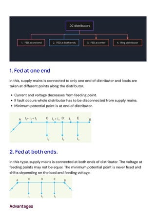
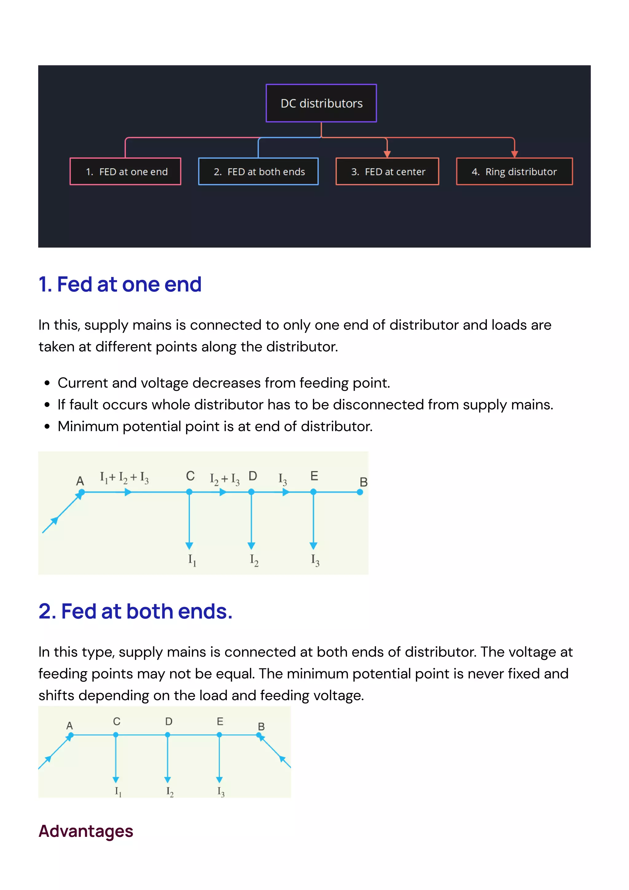
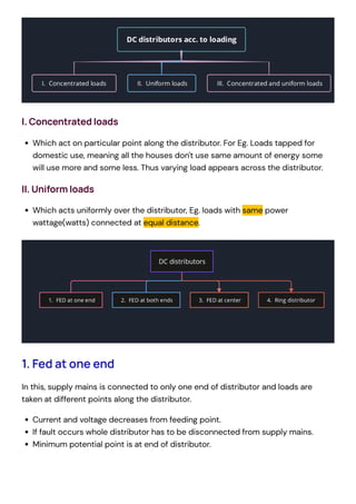
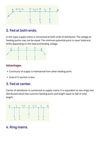
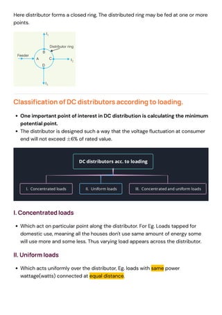
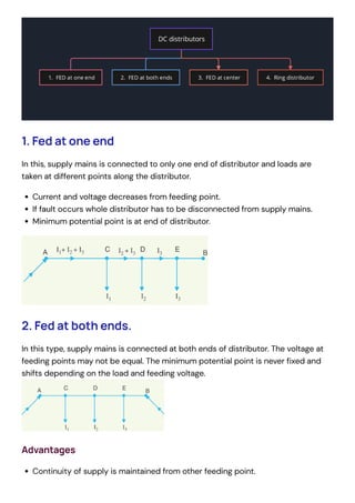
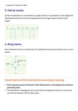
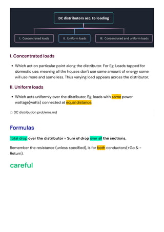
1. Fed at one end
In this, supply mains is connected to only one end of distributor and loads are
taken at different points along the distributor.
Current and voltage decreases from feeding point.
If fault occurs whole distributor has to be disconnected from supply mains.
Minimum potential point is at end of distributor.
2. Fed at both ends.
In this type, supply mains is connected at both ends of distributor. The voltage at
feeding points may not be equal. The minimum potential point is never fixed and
shifts depending on the load and feeding voltage.

Advantages
Continuity of supply is maintained from other feeding point.
Area of X-section is less.
3. Fed at center.
Center of distributor is connected to supply mains. It is equivalent to two singly fed
distributed which has common feeding point and length equal to half of total
length.
4. Ring mains.
Here distributor forms a closed ring, The distributed ring may be fed at one or more
points.
Classification of DC distributors according to loading.
One important point of interest in DC distribution is calculating the minimum
potential point.
The distributor is designed such a way that the voltage fluctuation at consumer
end will not exceed % of rated value.
±6
I. Concentrated loads
Which act on particular point along the distributor. For Eg. Loads tapped for
domestic use, meaning all the houses don't use same amount of energy some
will use more and some less. Thus varying load appears across the distributor.
II. Uniform loads
Which acts uniformly over the distributor, Eg. loads with same power
wattage(watts) connected at equal distance.
1. Fed at one end
In this, supply mains is connected to only one end of distributor and loads are
taken at different points along the distributor.
Current and voltage decreases from feeding point.
If fault occurs whole distributor has to be disconnected from supply mains.
Minimum potential point is at end of distributor.
2. Fed at both ends.
In this type, supply mains is connected at both ends of distributor. The voltage at
feeding points may not be equal. The minimum potential point is never fixed and
shifts depending on the load and feeding voltage.

Advantages
Continuity of supply is maintained from other feeding point.
Area of X-section is less.
3. Fed at center.
Center of distributor is connected to supply mains. It is equivalent to two singly fed
distributed which has common feeding point and length equal to half of total
length.
4. Ring mains.
Here distributor forms a closed ring, The distributed ring may be fed at one or more
points.
Classification of DC distributors according to loading.
One important point of interest in DC distribution is calculating the minimum
potential point.
The distributor is designed such a way that the voltage fluctuation at consumer
end will not exceed % of rated value.
I. Concentrated loads
Which act on particular point along the distributor. For Eg. Loads tapped for
domestic use, meaning all the houses don't use same amount of energy some
will use more and some less. Thus varying load appears across the distributor.
II. Uniform loads
Which acts uniformly over the distributor, Eg. loads with same power
wattage(watts) connected at equal distance.
±6
1. Fed at one end
In this, supply mains is connected to only one end of distributor and loads are
taken at different points along the distributor.
Current and voltage decreases from feeding point.
If fault occurs whole distributor has to be disconnected from supply mains.
Minimum potential point is at end of distributor.
2. Fed at both ends.
In this type, supply mains is connected at both ends of distributor. The voltage at
feeding points may not be equal. The minimum potential point is never fixed and
shifts depending on the load and feeding voltage.

Advantages
Continuity of supply is maintained from other feeding point.
Area of X-section is less.
3. Fed at center.
Center of distributor is connected to supply mains. It is equivalent to two singly fed
distributed which has common feeding point and length equal to half of total
length.
4. Ring mains.
Here distributor forms a closed ring, The distributed ring may be fed at one or more
points.
Classification of DC distributors according to loading.
One important point of interest in DC distribution is calculating the minimum
potential point.
The distributor is designed such a way that the voltage fluctuation at consumer
end will not exceed % of rated value.
±6
Formulas
Total drop over the distributor = Sum of drop over all the sections.
Remember the resistance (unless specified), is for both conductors(+Go & -
Return).
careful
I. Concentrated loads
Which act on particular point along the distributor. For Eg. Loads tapped for
domestic use, meaning all the houses don't use same amount of energy some
will use more and some less. Thus varying load appears across the distributor.
II. Uniform loads
Which acts uniformly over the distributor, Eg. loads with same power
wattage(watts) connected at equal distance.
DC distribution problems.md
Formulas
Total drop over the distributor = Sum of drop over all the sections.
Remember the resistance (unless specified), is for both conductors(+Go & -
Return).
careful


Don't forget to divide by 2 since you are taking r to be
resitance of 100M for both return and +ve wire.
Formulas
Total drop over the distributor = Sum of drop over all the sections.
Remember the resistance (unless specified), is for both conductors(+Go & -
Return).
careful


Don't forget to divide by 2 since you are taking r to be
resitance of 100M for both return and +ve wire.
Don't forget to divide by 2 since you are taking r to be
resitance of 100M for both return and +ve wire.

DC distribution system.pdf

  • 1.
    1. Fed atone end In this, supply mains is connected to only one end of distributor and loads are taken at different points along the distributor. Current and voltage decreases from feeding point. If fault occurs whole distributor has to be disconnected from supply mains. Minimum potential point is at end of distributor. 2. Fed at both ends. In this type, supply mains is connected at both ends of distributor. The voltage at feeding points may not be equal. The minimum potential point is never fixed and shifts depending on the load and feeding voltage. Advantages
  • 2.
    Continuity of supplyis maintained from other feeding point. Area of X-section is less. 3. Fed at center. Center of distributor is connected to supply mains. It is equivalent to two singly fed distributed which has common feeding point and length equal to half of total length. 4. Ring mains. Here distributor forms a closed ring, The distributed ring may be fed at one or more points. Classification of DC distributors according to loading. One important point of interest in DC distribution is calculating the minimum potential point. The distributor is designed such a way that the voltage fluctuation at consumer end will not exceed % of rated value. ±6
  • 3.
    I. Concentrated loads Whichact on particular point along the distributor. For Eg. Loads tapped for domestic use, meaning all the houses don't use same amount of energy some will use more and some less. Thus varying load appears across the distributor. II. Uniform loads Which acts uniformly over the distributor, Eg. loads with same power wattage(watts) connected at equal distance. 1. Fed at one end In this, supply mains is connected to only one end of distributor and loads are taken at different points along the distributor. Current and voltage decreases from feeding point. If fault occurs whole distributor has to be disconnected from supply mains. Minimum potential point is at end of distributor.
  • 4.
    2. Fed atboth ends. In this type, supply mains is connected at both ends of distributor. The voltage at feeding points may not be equal. The minimum potential point is never fixed and shifts depending on the load and feeding voltage. Advantages Continuity of supply is maintained from other feeding point. Area of X-section is less. 3. Fed at center. Center of distributor is connected to supply mains. It is equivalent to two singly fed distributed which has common feeding point and length equal to half of total length. 4. Ring mains.
  • 5.
    Here distributor formsa closed ring, The distributed ring may be fed at one or more points. Classification of DC distributors according to loading. One important point of interest in DC distribution is calculating the minimum potential point. The distributor is designed such a way that the voltage fluctuation at consumer end will not exceed % of rated value. I. Concentrated loads Which act on particular point along the distributor. For Eg. Loads tapped for domestic use, meaning all the houses don't use same amount of energy some will use more and some less. Thus varying load appears across the distributor. II. Uniform loads Which acts uniformly over the distributor, Eg. loads with same power wattage(watts) connected at equal distance. ±6
  • 6.
    1. Fed atone end In this, supply mains is connected to only one end of distributor and loads are taken at different points along the distributor. Current and voltage decreases from feeding point. If fault occurs whole distributor has to be disconnected from supply mains. Minimum potential point is at end of distributor. 2. Fed at both ends. In this type, supply mains is connected at both ends of distributor. The voltage at feeding points may not be equal. The minimum potential point is never fixed and shifts depending on the load and feeding voltage. Advantages Continuity of supply is maintained from other feeding point.
  • 7.
    Area of X-sectionis less. 3. Fed at center. Center of distributor is connected to supply mains. It is equivalent to two singly fed distributed which has common feeding point and length equal to half of total length. 4. Ring mains. Here distributor forms a closed ring, The distributed ring may be fed at one or more points. Classification of DC distributors according to loading. One important point of interest in DC distribution is calculating the minimum potential point. The distributor is designed such a way that the voltage fluctuation at consumer end will not exceed % of rated value. ±6
  • 8.
    Formulas Total drop overthe distributor = Sum of drop over all the sections. Remember the resistance (unless specified), is for both conductors(+Go & - Return). careful I. Concentrated loads Which act on particular point along the distributor. For Eg. Loads tapped for domestic use, meaning all the houses don't use same amount of energy some will use more and some less. Thus varying load appears across the distributor. II. Uniform loads Which acts uniformly over the distributor, Eg. loads with same power wattage(watts) connected at equal distance. DC distribution problems.md
  • 9.
    Formulas Total drop overthe distributor = Sum of drop over all the sections. Remember the resistance (unless specified), is for both conductors(+Go & - Return). careful Don't forget to divide by 2 since you are taking r to be resitance of 100M for both return and +ve wire.
  • 10.
    Formulas Total drop overthe distributor = Sum of drop over all the sections. Remember the resistance (unless specified), is for both conductors(+Go & - Return). careful Don't forget to divide by 2 since you are taking r to be resitance of 100M for both return and +ve wire.
  • 11.
    Don't forget todivide by 2 since you are taking r to be resitance of 100M for both return and +ve wire.