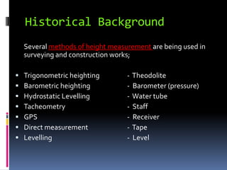
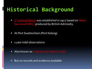
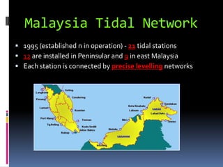
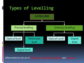
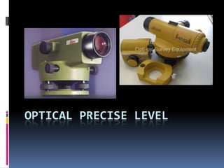
The document discusses precise leveling, including its aims, concepts, history in Malaysia, equipment, and types. Precise leveling is needed to establish accurate height networks and transfer heights precisely for engineering works. It requires specialized optical, motorized, or digital leveling instruments and invar staffs read to millimeters. Malaysia's first vertical datum was established in 1912, and its current tidal network helps define an accurate national geodetic vertical datum.
Introduction, electromagnetic spectrum, electromagnetic distance measurement, types of EDM instruments, electronic digital theodolites, total station, digital levels, scanners for topographical survey, global positioning system.
Surveying Engineering
Contour & Contouring
In this lecture we will cover
definitions.
Characteristics of contour lines.
Contours used by Engineers .
Methods of locating contour.
Method of Interpolation Contours.
Contour & Contouring
A map showing the natural and cultural features as well
as showing the nature of the surface of the land (topography of the
land) of the up and downs and its representation in (3D)three
dimensions.
A contour is a line drawn on a plan joining all points of the same
height above or below a datum.
Or A contour line
is a line that passes through points having the same elevation.
contour interval
is the constant vertical distance(VD) between any two
consecutive contours is called the contour interval
. The contour interval on this map is 20m
-The choice of suitable contour interval depends on several
factors.
-Topographic Maps
-Characteristics of contour lines.
-Contours are used by Engineers to:
-Methods of locating contour:
A- The direct methods
1- Level and staff method.
2- Plan table and alidade method.
Direct method procedure:
In this method the actual contour is pegged out on the ground and its
planimetric position located. A back-sight is taken to an appropriate BM and
the HPC of the instrument is obtained, say( 34.800m.) A staff reading of
0.800m would then place the foot of the staff at the( 34m )contour level. The
staff is then moved throughout the terrain area, with its position pegged at
every 0.800m reading. In this way the 34m contour is located. Similarly a
staff reading of (1.800m) gives the 33m contour and so on. The planimetric position of the contour needs to be located using an appropriate survey technique.
1- Grid method:-
Methods of Contouring
B- Indirect contouring
*Method of Interpolation Contours.
-Plotting contours.
Prepared by:
Asst. Prof. Salar K.Hussein
Mr. Kamal Y.Abdullah
Asst.Lecturer. Dilveen H. Omar
Erbil Polytechnic University
Technical Engineering College
Civil Engineering Department
*Introduction
*Controls For Setting Out
*Horizontal control
*Vertical control
*SETTING OUT A BUILDING
*The equipment required for the job
*Method(1):-By using a Circumscribing Rectangle
*Method(2):- By using centre-line-rectangle
* Setting out of culverts
*SETTING OUT A TUNNEL
Steve AuCoin & James Thompson's presentation at Geomatics Atlantic 2012 (www.geomaticsatlantic.com) in Halifax, June 2012. More session details at http://lanyrd.com/2012/geomaticsatlantic2012/sryrx/ .
Visual odometry & slam utilizing indoor structured environmentsNAVER Engineering
Visual odometry (VO) and simultaneous localization and mapping (SLAM) are fundamental building blocks for various applications from autonomous vehicles to virtual and augmented reality (VR/AR).
To improve the accuracy and robustness of the VO & SLAM approaches, we exploit multiple lines and orthogonal planar features, such as walls, floors, and ceilings, common in man-made indoor environments.
We demonstrate the effectiveness of the proposed VO & SLAM algorithms through an extensive evaluation on a variety of RGB-D datasets and compare with other state-of-the-art methods.
The presentation covers digital Voltmeter, RAMP Techniques, digital Multi-meters. It also covers Oscilloscope; Introduction and Basic Principle, CRT, Measurement of voltage, current, phase and frequency using CRO, Introduction of Digital Storage Oscilloscope and its comparison over analogue CRO
Processing steps - Power Lines LiDAR Mapping projectsDIELMO3D
Power Lines LiDAR mapping and Offending vegetation detection.QA/QC Power lines analysis and Corridor Mapping. Customized engineering services from LiDAR procesing. PLS-CADD
The content is related to Analog electronics. The prEsentation contains ADC process, Sampling and holding, Quantizing and encoding, Flash ADC, Pipeline ADC etc.
Electrical measurement & measuring instruments [emmi (nee-302) -unit-5]Md Irshad Ahmad
(1) Digital Measurement of Electrical Quantities-Concept of digital measurement, Block diagram, Study of digital voltmeter, Frequency meter, Spectrum analyzer, Electronic multimeter.
(2) Cathode Ray Oscilloscope-Basic CRO circuit (block diagram), Cathode Ray Tube (CRT)
& its components,Applications of CRO in measurement, Lissajous Pattern, Dual trace & dual beam oscilloscopes.
Signal conditioning & condition monitoring using LabView by Prof. shakeb ahm...mayank agarwal
Lecture handout given by Prof. shakeb ahmad khan on Signal conditioning & condition monitoring using LabView in National Workshop on LabVIEW and its Applications.Organized at Dayalbagh Educational Institute,Dayalbagh,AGRA from 28-29 August 2015.
1. SUG213 : ENGINEERING SURVEYING II
PRECISE
LEVELLING
INTRODUCTION AND INSTRUMENTATION
Lecture By:
Zuraihan Mohamad
Dept. of Surveying Sciences & Geomatics
FSPU
UiTM Arau
2. Aim Of The Topic
At the end of this lecture, student should be
able to :
Understand what is precise levelling and the needs.
Understand the methods and instrumentation of
precise levelling
3. Lecture content
Concept of levelling
Historical background of Precise Levelling in Malaysia
National Geodetic Vertical Datum (NGVD)
Malaysia Tidal Network
Types of Levelling
Precise Levelling
Equipment of precise levelling
Optical precise levelling
Motorized l precise levelling
Digital precise levelling
4. QUESTION… Before we begin
What is P.L?
Why do we need P.L?
Are there any differences between P.L n
O.L??
Say that that there are indeed differences,
they are in terms of what???
5. Concept of Levelling
The concept of levelling is based on the horizontal line
of the instrument (level) with the level line of the point
on the earth.
If the heights of A and B can be measured, the height
differences can be calculated using the formula :
h = a - b
If the RLA is known, RLB can be calculated as:
RL B = RLA + h
6. Memory Test… Which is what???
Staff Staff
Level ???
a b
Level line through level instrument
Level Line through B
B
Level Line through A
A
???
???
???
7. Concept of Levelling
The name given to the method of determining differences in
heights between points
A method of height transfer from one point to another
Being used in Geodetic and Engineering Surveys
Using special instrument called : level
8. Historical Background
Several methods of height measurement are being used in
surveying and construction works;
Trigonometric heighting - Theodolite
Barometric heighting - Barometer (pressure)
Hydrostatic Levelling - Water tube
Tacheometry - Staff
GPS - Receiver
Direct measurement - Tape
Levelling - Level
9. 1st vertical datum was established in 1912 based on Mean
Sea Level (MSL) produced by British Admiralty.
At Port Swettenham (Port Kelang)
1 year tidal observations
Also known as Land Survey Datum (LSD)
But no records and evidence available
10. Mean Sea Level
Average level taken up by the sea
Coincide with the Geoid
Change regularly due to tide
Best observation period is 18.6 years
Use of Tide Observation Data
Determine precise vertical datum
Information for research in geodesy, geodynamic and scientific studies
Tide & flood prediction
Port activities and navigation
Marine boundaries, hydrography and aquaculture
Delivery of fixed record of sea level
To obtain tidal harmonic constant
To study tidal characteristics
For tidal prediction.
11. National Geodetic Vertical
Datum (NGVD)
JUPEM initiated the establishment of NGVD
12 tidal stations were established in 1981
Objectives:
To observe tide levels continuously
18.6 years complete cycle of moon regression
To obtain tidal harmonic constants
To study tidal characteristics
For tidal prediction
12. Malaysia Tidal Network
1995 (established n in operation) - 21 tidal stations
12 are installed in Peninsular and 9 in east Malaysia
Each station is connected by precise levelling networks
14. Types of Levelling
LEVELLING
Precise levelling Ordinary levelling
Optical level Motorized Optical Level Digital
level level
Digital level
Differentiated by the set of instruments, observation methods and accuracy
15. Precise Levelling
Also known as the highest order of levelling works
Readings observed and recorded to decimals of a millimeter
Used for :
Basic levelling framework of a country
Transfer height to bench marks
Precision engineering structure
Irrigation Scheme, Dam, Tunnels
Precision dimensional surveys
18. 1. Optical Precise Level
Precise type
With parallel plate micrometer
Manufacturer quote: “Std dev less than 1 mm per
double run of levels over a km” can be considered as
precise
Glass diaphragms (eye piece) – vertical line, levelling
line and two stadia lines (upper and lower)
22. Components
3. Precise Staff
Two precise/Invar staffs
Invar Strip – stable material (low
sensitivity to heat)
Small expansion coefficient
Graduations 0.02ft / 0.01 m on
invar strip
With handle / staff holder
To be calibrated every 3 months
24. 2. Motorized Precise Level
Were used in the DSMM (Late 80s) - No longer used
Modification of conventional method
Three vehicles – 1 for the level and observer, 2 for the staffs
Invar staffs are fitted to the vehicles
Advantage:
Faster and convenient
Disadvantage:
High cost
Not suitable in busy roads
26. 3. Digital Precise Level
Use digital level (automatic level) and bar-coded
staffs
Use infrared detector to scan the bar-coded staff
Scanned staff image is compared to actual staff
pattern stored in the instrument
Provide staff reading and horizontal distance
Advantages:
Levels are recorded automatically
Reduce human error (reading and booking)
Reduce observation time
Include processing software
28. Leica DNA 03 Digital Precise Level
Elements:
1 On/ off button 16 PCMCIA or CF-card with
2 Base plate adapter (optional)
3 Foot screws 17 Battery GEB121 (optional)
4 Horizontal circle 18 Battery adapter GAD39; 6
5 Lever to unlatch battery single cells (optional)
6 Battery compartment 19 Light duct for circular level
7 Button to unlatch card compartment 20 Plug stopper for crosshair
cover adjustment knob
8 Card compartment cover 21 RS232 serial interface
9 Display with external power supply
10 Circular level 22 Measuring button
11 Hand grip with aiming sight 23 Focusing drive
12 Ocular 24 Endless horizontal drive
13 Keyboard (bi-directional)
14 Objective
15 Battery GEB111 (optional)
29. Leica DNA 03 Digital Precise Level
Characteristics:
Limited target distance <30m
Minimum ground clearance of >0.5m required to
minimized refractionary influences of ground proximity.
Double observance (BFFB, aBFFB) to increase the reliability
of measurement and to reduce possible errors caused by
staff sinking.
Applying alternating observations procedures (aBFFB =
BFFB FBBF) to eliminate horizontal tilt ( residual error of
the automatic compensator)
Use an umbrella in strong sunlight.
31. 1. Base/Change Plate
Staffs are to be supported on turning points
Made from mild steel
Round head and collars
To reduce error during turning (for soft ground)
32. 2. Handles/Bipods
To support precise staff
For long observation period
Stable (verticality)