Downloaded 11 times
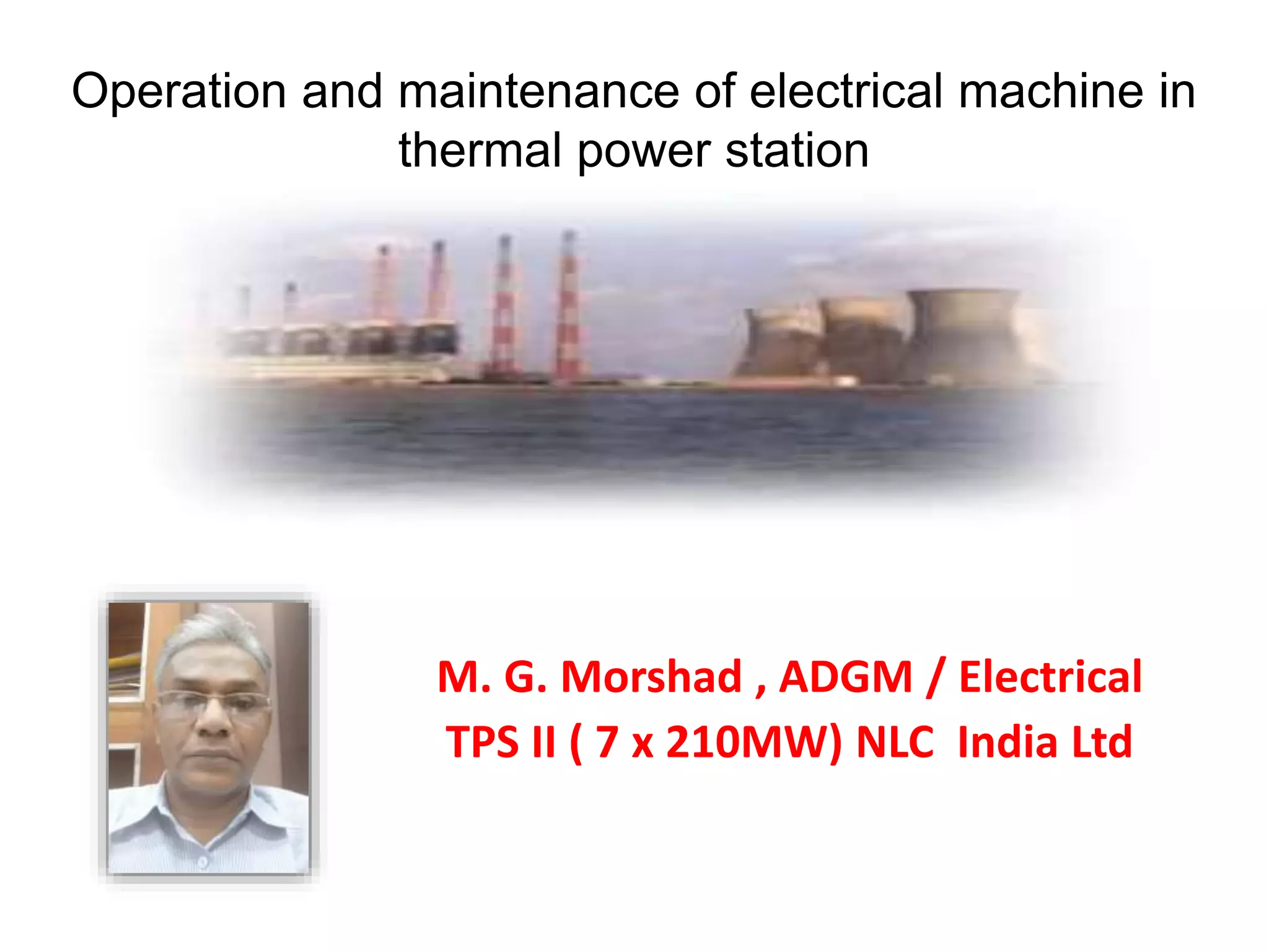

1. The document discusses the operation and maintenance of electrical systems in thermal power stations, including generators, transformers, motors, and distribution systems. 2. It covers topics such as AC and DC systems, single and three-phase systems, delta and star connections, grounded and ungrounded systems, and losses in electrical machines like hysteresis and eddy current losses. 3. The document also discusses components like transmission lines, substations, and the arrangement of electrical systems in thermal power stations.


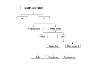
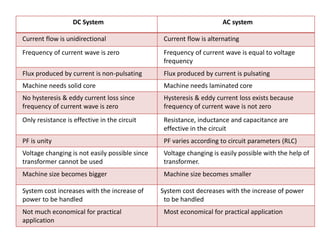
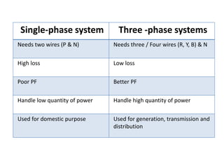
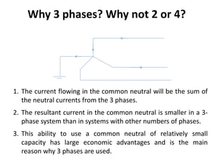
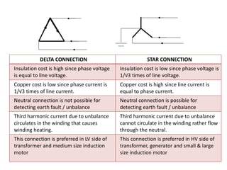
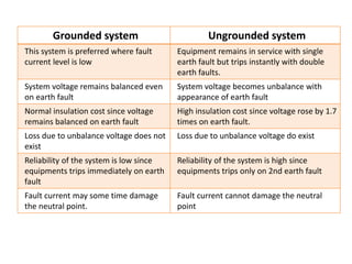
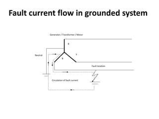
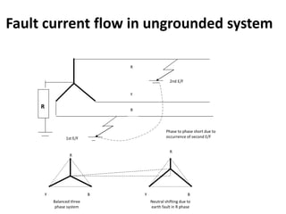
![[PPT] on Steam Turbine](https://cdn.slidesharecdn.com/ss_thumbnails/spsharmafinalppt-140608082156-phpapp01-thumbnail.jpg?width=640&height=640&fit=bounds)


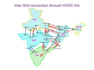
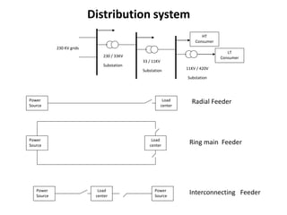
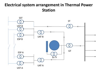
![transformhdhhjytbjguihgters_g_62[2].pptx](https://cdn.slidesharecdn.com/ss_thumbnails/transformersg622-250718173118-5265e8c2-thumbnail.jpg?width=640&height=640&fit=bounds)