Downloaded 238 times

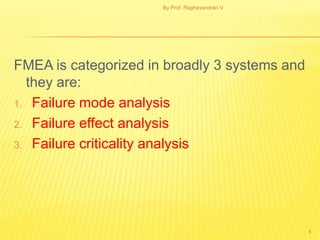
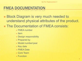
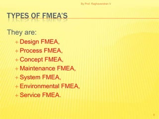
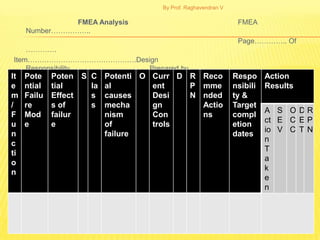
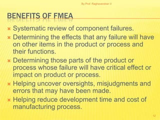
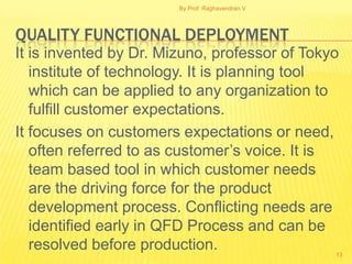
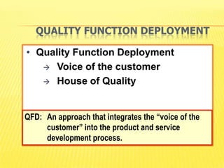
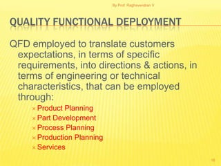


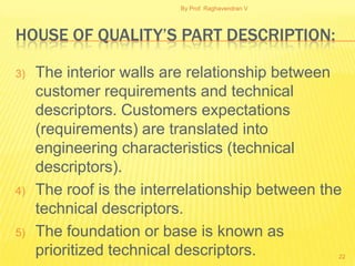
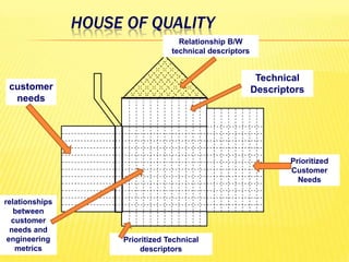


FMEA is a technique used to analyze potential failure modes within a system or design. It involves analyzing the potential failure of components, determining the effects of failures, and identifying actions to address potential causes and reduce risk. The document discusses FMEA methodology including failure mode analysis, failure effect analysis, and failure criticality analysis. It also discusses FMEA documentation and different types of FMEAs. Quality Functional Deployment (QFD) translates customer needs and expectations into engineering specifications. It uses a tool called the House of Quality to document customer requirements and map them to technical design requirements.